


Keywords
Abstract
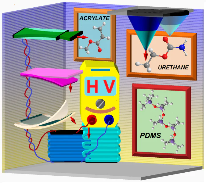
The review describes the dielectric elastomer actuators (DEAs), a class of soft mechanical actuators made of functional polymeric materials and composites, which are capable to act as artificial muscles. The principles of operation, design, methods of DEAs fabrication and the required equipment are comprehensively described. Most frequently used DEA polymers (polyacrylates, polyurethanes, siloxanes) are considered in detail, and various modern advanced modification methods are listed. Polydimethylsiloxanes (PDMSs) are the most promising materials as DEA membranes. The review presents the state-of-the-art techniques for significant improvement of the performance of PDMSs: the reinforcement of a silicone matrix with different dispersed fillers, the chemical modification using compounds with large dipole moments to finely tune the dielectric characteristics of the silicones, etc. A new classification of DEAs is proposed. The design of more than 20 DEA devices are presented.
The bibliography includes 269 references.
1. Introduction
An actuator is a device that is responsible for the movement and operation of a mechanism or a system. The devices described hereinafter have no discrete moving parts, being flexible in movement, which is impossible in conventional mechanical, hydraulic or pneumatic systems. Therefore, in this review by the term actuator we understand the flexible mechanical units fabricated from functional polymeric materials and composites and are often called artificial muscles.
For many years, biology was a source of ideas for researchers and engineers. It seemed that the simulation modeling of biological objects, such as tissues, bones, joints, muscles, valves, etc., using the newly designed materials, devices, mechanisms and, in general, technologies would soon lead to the creation of a full-scale anthropomorphic robot. Although this idea was not mechanically implemented as yet, it was transformed into industrial robotic systems, such as manipulators, grips, etc. Increased computing resources and the progress in artificial intelligence resulted in the manufacturing of anthropomorphic or human-like hard robotic constructions, such as the robot FEDOR* or Spot®. However, these robots are still only computerized machines composed of mechanical drives, levers, hinges and shells.
The next step currently being undertaken by science and technology is the creation of another type of devices, namely, soft robots, which are, in many respects, more similar to their biological prototype. These devices emerge on the basis of new functional materials, which can change their properties and shape in response to external stimuli and, for example, can transport cargo, be used to control valves, etc. The characteristics flexible or soft refer both to the body of the robotic device and its components performing mechanical work, i.e. artificial muscles.
Materials used in conventional robotics (e.g., metals or solid plastics) have Young's moduli ranging from 109 to 1012 Pa, whereas the moduli of materials of living organisms (e.g., skin or muscle tissue) are generally several order of magnitude smaller varying in the range from 104 to 108 Pa (Fig. 1).1 Soft robots are fabricated from functional materials with properties similar to those of biological prototypes, wherein necessary sensors, computer controllers, power supply systems and a set of artificial muscles as actuators, which are required for operation of the device, are incorporated into the final robotic system.
![[{"id":"o5sAWTSxTG","type":"paragraph","data":{"text":"Young's moduli of different materials and substances, including those used in flexible robotic devices. The Figure was prepared by the authors using original data from the study<sup>1</sup>"}}]](/storage/images/resized/PaWvvf9OdMbtXrdo5piVgKluKxi9vJvroL2qEVnp_xl.webp)
Currently, devices, which are most promising in terms of application in robotic or biomechanical systems, are those based on various electroactive polymers (EAPs), i.e., polymers driven by electrical signals, the elasticity of such materials is quite consistent with that of biological systems (see Fig. 1).
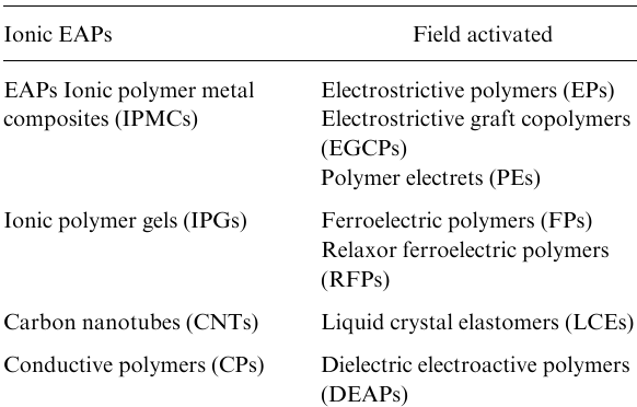
Electroactive polymers are divided into two types. One type of EAPs, ionic (conductive) EAPs, are driven by the mobility or diffusion of ions in a polymeric material or a material of a device and can be actuated by either an electric field or changes in the parameters of the medium, such as pH, temperature, etc. It is worth noting that these devices have a rather long response time because the physical movement of the substance (ions) in the medium is required; liquid electrolytes remain a necessary medium for particular configurations of ionic EAPs. Carbon nanotubes, as materials for actuators, are not polymers but they are considered together with ionic EAPs, because the operation principles of devices built from carbon nanotubes are the same as those of ionic EAPs.
The application of an electric field to the device or, which is the same, the application of a voltage to the electrodes of the device, is necessary and sufficient for the actuation of another type of EAPs, non-conductive EAPs activated by an electric field. For example, electrostrictive polymers (EPs) have a spontaneous electric polarization. They change the size upon actuation due to the movement of dipoles in the bulk of the material in the presence of an electric field. Actuators based on dielectric films/membranes coated with electrodes are assigned to electric field activated EAPs.
This division is commonly accepted to classify materials for actuators (artificial muscles). It is described in the reviews concerning EAPs and published in different years.1--10
A number of EAPs were successfully used for a long time to design and fabricate actuators, whereas other EAPs, for example ferroelectric polymers, are currently under extensive investigation and are being adapted to the requirements placed on functional materials for artificial muscles.
We cannot but mention several versions of flexible actuators of mechanical type. Pneumatic artificial muscles developed in the early 1950s by J.L.McKibben are rubber, i.e., flexible, tubes closed on both sides. When pressurized with air, the diameter of the tube increases radially, while its length decreases, causing the contraction of the muscle up to 35% of the length, thereby activating the actuator.11,12 Another example is a muscle made of twisted fishing line, e.g., Nylon.13--15 Nylon shrinks in length upon heating, and the heating of the device leads to an additional tightening of coiled fibres and a significant (up to 40--50%) decrease in the length of the muscle at 150 °C.
New types of muscles were designed also, for example, thermomechanical muscles activated thermally or thermoelectrically.16 Available EAPs are modified, their composition is optimized, procedures for their fabrication are improved and applications in the structures of actuators are upgraded; other, previously unknown, muscles, e.g., thermally activated shape memory polymers,17 magnetoactive elastomers,18 etc., became more widely used. Currently, this field of materials science is extensively developed to meet the requirements of modern robotics and biomechanics.
Some types of EAPs can be used as pressure or force sensors. The configurations of such sensors are very similar to those of actuators based on the same EAPs, but their operating principle is opposite. Thus, a change in the shape (stretching or contraction) leads to changes in the electric parameters of the device and allows one, after the appropriate calibration, to control the mechanical parameters, such as changes in the geometry of the sensor or the pressure on the sensor. An actuator--sensor pair, on its own or with the involvement of electronics, forms a self-controlled system generally with a negative feedback loop, making it possible to design autonomous robotic devices.
This review is an attempt to comprehensively cover the state-of-the-art materials and structures of different types of actuators, primarily, dielectric elastomer actuators, whereas most of the available reviews are focused on a particular specific field of their application, for example, in soft robots,6,8,10,19 medicine20 or as biomimetic constructs,3,21 micromechanical devices,2,7 etc. This review describes in detail dielectric elastomer actuators, types of elastomers from which they are fabricated, methods for the synthesis of these materials, etc., and also briefly considers actuators based on different EAPs and demonstrates the place of DEAPs among other EAPs (see Table 1). We believe that the comprehensive consideration of a broad scope of materials, types and configurations of actuators with special attention to dielectric elastomer actuators as the most promising type of actuators and an attempt to classify the configurations of DEAs will be interesting for a wide range of readers.
*https://fpi.gov.ru/projects/khimiko-biologicheskie-i-meditsinskie-issledovaniya/fedor/ (access date 27.03.2023)
1.1 Electroactive polymers
1.1.1. Ionic polymer-metal composites
Ionic polymer-metal composite (IPMC) actuators are composed of an ion-exchange membrane with thin flexible conductive electrodes.22,23 The actuation, i.e., the application of a voltage to electrodes, induces the migration of electrolyte ions in the membrane, causing the swelling on one side of the membrane nd contraction on its other side, resulting in the bending strain (Fig. 2a,b).10,24
![[{"id":"vTzPp1_2CV","type":"paragraph","data":{"text":"IPMC membrane with electrodes: (<i>a</i>) the membrane in the initial state; (<i>b</i>) the actuated membrane; (<i>c</i>) the structural formulas of the materials Nafion® and Flemion®. The Figure was prepared by the authors using original data from the studies<sup>10,24</sup>"}}]](/storage/images/resized/TAhjsbY1MEt6LBbDuxOQQsnP4s5VhSbv0bUh4p93_xl.webp)
The most popular materials for IPMC membranes are perfluorinated sulfo-containing polymers such as Nafion® and Flemion® (Fig. 2c)25 or styrene/divinylbenzene polymers bearing anionic groups,24,26 more complex systems, e.g., polymers based on crown ethers containing sulfonated poly(arylene ether ketone), materials based on sulfonated styrene ethylene butylene styrene block copolymer, nanodiamond-filled polymer composites,27--29 etc. The ion-exchange material MF-4SK is also available.30
Materials for IPMC membranes contain both hydrophilic anionic segments and hydrophobic regions, the latter having channels that provide the migration of cations and the solvent. The membrane strain is induced due to diffusion of mobile cations under an applied electric field, resulting in the mass transfer from the positively charged side of the membrane to the negatively charged side.31
The control voltages of IPMCs are a few volts. Ionic polymer-metal composites are well suited as soft bending actuators of different shape and size,32--34 micropumps,22,24,35 etc. Different procedures for the manufacture of such devices are described in detail in the study;36 the application of modern tunable manufacturing processes for the fabrication of IPMC actuators are considered in the publication.37
1.1.2. Ionic polymer gels
Ionic polymer gels (IPGs) belong to hydrogels and they are generally network polymers, e.g., weakly cross-linked poly(acrylic acid), plasticized polyvinyl chloride, etc.38--40 Hydrogel placed in a liquid begins to swell. This may be caused by different factors, for example, poly(acrylic acid) gel is ionized in response to an increase in pH and swells.41
Ionic gels respond to an applied electric field.42 The electric field induces the migration of hydrogen ions from the gel or inside it, also changing the pH value, which, in turn, leads to reversible gel swelling. Hydrogels as materials for actuators were studied in the works;43--45 a number of configurations of IPG actuators were described in the studies.46,47
1.1.3. Carbon nanotubes
Since their discovery by Iijima,48 CNTs have attracted great interest due to their unique mechanical and electrical properties and also the possibility of their functionalization and incorporation in composite materials. Carbon nanotubes have high Young s moduli similar to that of diamond of about 1012 Pa, and their strength at break is high, varying from 20 to 40 GPa, which is an order of magnitude higher compared to any other fibre.49 However, the mechanical properties of CNT bundles and mats used in practice are much lower because CNTs are held in them by relatively weak van der Waals forces.50
Carbon nanotubes configured as porous sheets are expanded when placed in an electrolyte under the voltage applied between CNTs and the counter electrode (which probably also consists of CNTs).
The application of a potential leads to the formation of an electrical double layer at the nanotube/electrolyte interface (see Fig. 3a),26,51 in which the electric charge concentrated at the carbon atoms is equilibrated by the ionic charge in the electrolyte. It is assumed that during electron injection, the accumulated charge of the nanotubes is sufficient for a change in the C-C bond length due to Coulomb repulsion and, probably, other factors.
![[{"id":"k-1Kp2YQ_V","type":"paragraph","data":{"text":" Carbon nanotube actuators: (<i>a</i>) a bending actuator;<sup>50,52</sup> (<i>b</i>) CNT aerogel (material for actuator);<sup>53</sup> (<i>c</i>) a CNT torsional actuator.<sup>54,55</sup> Reproduced with the permission of AAAS<sup>50</sup> and John Wiley and Sons.<sup>52,54</sup>"}}]](/storage/images/resized/sTgv82JgVnAtXXVY32ApHGZLsLyjodH2hGVjEmM1_xl.webp)
The upper part of Fig. 3a shows CNT electrodes (sheets) with an applied voltage, anions and cations surrounding CNTs; the lower part presents the result of actuation; the bending direction depends on the polarity of the applied voltage. Carbon nanotubes have a low operating voltage of about 1 V.56
Aerogels composed of CNTs57,58 function in another (air) medium, are fabricated from highly ordered CNTs and are capable of anisotropic linear expansion up to 220% (Ref. 58) at temperatures from 80 to 1900 K. When a high positive voltage (up to 5 kV), with respect to the counter electrode (Earth), is applied, the Coulomb repulsion between the nanotubes leads to an increase in the aerogel volume. The initial volume is restored after switching off the voltage.
Twisted carbon nanotube yarns are promising candidates for CNT actuators;59 the actuation is electrothermal; and such actuators are often torsional (Fig. 3c).54,55 Flexible muscles made of twisted fishing lines were described previously (see the Introduction).60
1.1.4. Conductive polymers
Conductive polymer (CP) actuators were proposed for the first time by Baughman et al.61 Conductive polymers change their shape due to the migration of ions during the redox cycle.
Conductive polymers are electronically conductive organic materials with a complex structure, as shown, for example, in Fig. 4c. The electrochemical oxidation/reduction leads to the addition or removal of the charge from the polymer backbone and the ion flow to equilibrate these charges4,26,62,63 (see Fig. 4a,b). This flow of ions and, to some extent, of the solvent causes the swelling (Fig. 4b) or contraction (Fig. 4a) of the material. The size changes are due primarily to the intercalation of ions between the polymer chains, although conformational changes of the backbone and the solvent flow also can play a certain role. The primary expansion occurs perpendicular to the polymer chain direction.63--65
![[{"id":"nBoYxZt7ZK","type":"paragraph","data":{"text":" Mechanism of the polypyrrole-based actuator membrane: (<i>a, c</i>) (upper), polypyrrole in the reduced state; (<i>b, c</i>) (lower) polypyrrole in the oxidized state, the ions are located between the chains (yellow/crimson and A ) and the solvent (red/blue/gray). The actuation occurs through intercalation and deintercalation of ions between the chains. Figures 4a and 4b are reproduced with the permission of Elsevier.<sup>4</sup> Figure 4c was prepared by the authors using original data from the study<sup>4</sup>"}}]](/storage/images/resized/fhC4n282EQoSJCZZhwVZibN8Xq8xH1uLw2dyD76E_xl.webp)
The most popular CPs used in actuators are polypyrrole and polyaniline; however, other conductive polymers are also employed.66,67 Fig. 4 shows the schematic representation of the polypyrrole chain in the oxidized and reduced states.
The operating voltage of such actuators is generally low (about 2 V). Since the CP materials are biocompatible, they are considered as potential biomimetic devices to use as interfaces with humans, which include the repeated blood vessel connection, the dynamic Braille recognition system, valves and catheters.68
1.1.5. Ferroelectric polymers and relaxor ferroelectric polymers
All types of ferroelectric polymers (FPs) and relaxor ferroelectric polymers (RFPs) have non-centrosymmetric structures with a spontaneous electric polarization. These polymers contain dipoles, which can be oriented in an electric field, with the polarization being retained. The ferroelectric properties are exhibited by poly(vinylidene fluoride) (PVDF) and its copolymers, e.g., poly(vinylidene fluoride-trifluoroethylene) (P(VDF–TrFE)) and so on, and also by odd-numbered polyamides, such as Nylon 7, Nylon 11 or their blends.69--72
All FPs contain polar side chains, which maintain stable polarized molecular configurations. Besides, the polar chains are packed so as to retain the initial polarization. For example, PVDF can form a number of crystalline phases, which differ in the conformation of the polymer molecules and their packing; the degree of crystallinity can be as high as 50--70%. The phases with a dipole moment appear when the packing of macromolecules allows the dipole moments of the side chains to be added together, thereby providing the polarization of the overall bulk of the crystallite. The so-called β phase has the highest polarity. The transitions between different polymorphs of PVDF are presented in the classical diagram from the publication.74 The phase transition leads to an extremely large change in the lattice constant and, consequently, to large bulk deformations, thereby allowing the use of such materials as artificial muscles (Fig. 5).75
![[{"id":"kFVV6cACHA","type":"paragraph","data":{"text":" Structures of the α (non-polar) and β (polar) phases of PVDF: (<i>a</i>) distances between the units of the backbone along the chains; (<i>b</i>), (<i>c</i>) distances across the polymer backbone.<sup>4</sup> Reproduced with the permission of Elsevier."}}]](/storage/images/resized/kl2I0Ju4lgVgNHrLWWujDMbQuEaYWMVHxJtwIMqF_xl.webp)
All known RFPs are based on the P(VDF–TrFE) copolymer. Relaxor ferroelectric polymers are characterized by a broad peak of dielectric permittivity and a strong frequency dispersion.76 This makes it possible to eliminate two main shortcomings of FPs, such as the high temperature (higher than the Curie point) of the paraelectric-ferroelectric transition necessary for the actuation of the device and the presence of a strong hysteresis, resulting in that the transition requires more energy and is poorly controlled. Relaxor ferroelectric polymers are promising candidates for artificial muscles. Procedures for decreasing the Curie point for RFPs are listed below:
- the formation of defects into the P(VDF–TrFE) copolymer to decrease the sizes of crystallites.77 The presence of smaller crystallites reduces the energy barrier for the paraelectric–ferroelectric transition, resulting in a smaller hysteresis;78
- the exposure P(VDF–TrFE) to high-energy electrons or protons for an efficient decrease in the Curie point to room temperature and the suppression of the hysteresis;78--80
- the introduction of bulky side chains into the copolymer81--84 (e.g., chlorofluoroethylene,83 chlorotrifluoroethylene81 or hexafluoropropylene85) to create polarization defects, destabilizing the ferroelectric phase.
1.1.6. Polymer electrets
Polymer electrets (PEs) are composite materials exhibiting piezoelectric effects due to the non-uniform distribution of the space charge in the bulk of the composite.86,87 Modern PEs are highly porous layered polymers schematically represented in Fig. 6a. Porous films are charged by means of corona discharge with a voltage varying from 5 to 10 kV. The application of the voltage to electrodes deposited on both sides of the electret film gives rise to an electric field within the pores and leads to the charge accumulation at the polymer--gas interface, the positive and negative charges being at the opposite sides of the pores (see Fig. 6b) to form macroscopic dipoles.77 The charges begin to interact and are ordered, which causes a change (decrease) in the thickness of the PE film. Polymer electrets can act as actuators or sensors.86 The optimization of the composition of the materials will increase the allowable maximum deformations of materials for PEs and will make it possible to use these materials in robotics.
![[{"id":"dVKan7aXcT","type":"paragraph","data":{"text":"Schematic representation of the operation of a polymer electret containing bipolar voids; (<i>a</i>) the electret with no voltage applied, the voids are expanded, (<i>b</i>) a high voltage is applied, the voids are contracted. The Figure was prepared by the authors using original data from the studies<sup>86</sup>"}}]](/storage/images/resized/Sqbqlp8cF3X6nVin7dz8Yzh38PMtKNgsVCOUD28k_xl.webp)
1.1.7. Electrostrictive graft copolymers
Electrostrictive graft copolymers (EGCPs) are copolymers, in which polar side chains are coordinated to form crystalline regions, which serve as polarizable units of the substance, providing the electrostrictive properties of EGCPs (Fig. 7).88
![[{"id":"dwtZkf5Mml","type":"paragraph","data":{"text":"Structure of crystallites in a electrostrictive graft copolymer.<sup>4</sup> Reproduced with the permission of Elsevier"}}]](/storage/images/resized/ku7eKn1RYwbLj2A0GwwXci0NKxocXctwwd780NJg_xl.webp)
When an electric field is applied to EGCPs, for example, consisting of the poly(chlorofluoroethylene) or poly(trifluoroethylene) backbones with P(VDF–TrFE) as side chains, polar crystallites are reoriented, resulting in the bulk deformation of the material.89 Su et al.90 described actuators based on EGCPs, bending either in one or in both directions.
1.1.8. Liquid crystal elastomers
Liquid crystal elastomers (LCEs) combine the properties of liquid crystals, exhibiting orientational order, and the properties of elastomeric networks.91 In 1975, P.-G.de Gennes predicted92 that the changes in the orientation of mesogenic groups in liquid crystals during the phase transition can lead to bulk stresses and deformations. In the study,93 LCEs were proposed for the first time for the application as artificial muscles.
Liquid crystal elastomers consist of mesogenic groups linked to each other through an elastic network polymer, providing the movement (rotation) of mesogenic groups relative to each other. The mechanism of actuation of LCE materials was described in detail in the sudies.94--97 For example, in nematic polymer systems, in which mesogenic groups are incorporated directly into the backbone, the chains are elongated when all mesogenic groups are aligned, the material being expanded;98--100 on the contrary, the material is relaxed when the order is absent and the chains are coiled into helices.101
The orientation can be changed under thermal and electrical stimuli.92,94,96,102--105 Electrically actuated LCEs contain polarized mesogenic groups, which are rearranged in the represented in Fig. 8.92
![[{"id":"9lqc2fcP0b","type":"paragraph","data":{"text":"Structural formula of a liquid crystal elastomer and the mechanism of its actuation: (<i>a</i>) the polysiloxane backbone (blue rectangles) and mesogenic groups (red ovals); (<i>b</i>) the orientation of mesogenic groups under an applied electric field.<sup>4</sup> Reproduced with the permission of Elsevier"}}]](/storage/images/resized/ieZHGPacVTCWi3xJjf6N7RFITtbiJfroEE9CcuzB_xl.webp)
1.1.9. Dielectric elastomers
The focus of this review is on the dielectric elastomer actuators, materials for such actuators and devices based on them. Dielectric elastomer actuators operate on the principle of the electrostatic deformation. The electrical voltage is applied to stretchables electrodes deposited on both surfaces of an elastomeric membrane (film), and the resulting electrostatic force between the opposite charges on the two electrodes (Maxwell stress) compresses the membrane in thickness. Since the available dielectric elastomers are incompressible (Poisson's ratio for these elastomers ν ≈ 0.5), such compression results in a corresponding stretch in the planar area of the membrane.
Actuators based on such materials have attracted a great interest because they can operate in different environments and in a wide temperature range and demonstrate high performance characteristics.
1.2. Energy density of materials
The energy density, the specific volumetric or gravimetric potential energy of deformation stored in the actuator material, is the most important parameter of the material of any type of actuators, which is responsible for the performance of the created device.
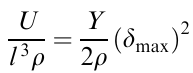
The potential energy of uniaxial compression
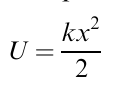
where x=lζ, ζ is the deformation of a cube of the material with an edge length l, k is its stiffness, k=Yl, and Y is the Young's modulus of the material. Designating the experimental maximum allowable strength of the material as δmax, one can calculate the maximum specific volumetric potential energy of deformation, i.e. the specific volumetric energy density (J m–3) of the deformed material
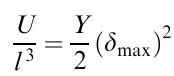
or the specific mass energy density
where ρ is the density of the actuator material.
An important field of research aimed at optimizing the materials for actuators is based on an increase in the specific parameters with the retention or improvement of the deformation characteristics of the materials.
The stress versus strain diagrams for the efficiency of actuation performance of different types of actuators (Fig. 9) were reported in a number of studies, for example, in the publications.7,20
![[{"id":"BKvmVmAdye","type":"paragraph","data":{"text":"Schematic diagram for the energy efficiency of different electroactive polymers.<sup>20</sup> The inclined lines indicate the volumetric energy densities. The regions corresponding to different EAPs are in different colours. Reproduced with the permission of IOP Publishing"}}]](/storage/images/resized/xiPuM773MxOZ24vFQOZCjO5J9mysa5UaHUuhI2TO_xl.webp)
As it is seen in Fig. 9, the parameters for each EAP material vary in wide ranges. This area of research is gradually developed, the properties of the materials are optimized, their energy density and maximum strain are increased. Meanwhile, this schematic diagram shows that the energy density, the maximum strain or both parameters of artificial muscles are already better compared to those of biological prototypes, which is encouraging for researchers and stimulates research on the optimization of the properties of EAPs, as well as on the systems of control and regulation by both a single actuator and a complex of interacting actuators of different types and the design of self-regulating systems.
2. Dielectric elastomer actuator devices
2.1. Principle of operation of dielectric elastomer actuators
In 1880, W.C.Röntgen performed the following experiment. A thin 16×100 cm natural rubber strip was prestretched to twice its original length, carbon electrodes were deposited on its both surfaces and a high voltage was applied, after which a change in the length of the strip was observed. He was the first to detect the change in the size of the dielectric polymer material (rubber) caused by the mutual attraction between the electrodes deposited on the surface (Maxwell stress) under the applied electric field.106
The principle of operation of a dielectric elastomer actuator is schematically represented in Fig. 10. DEAs are flexible DEAP membranes (in Fig. 10, shown in blue) coated on both sides with stretchable electrodes (in Fig. 10, shown in orange), so that DEA is a common planar capacitor, the gap between electrodes is filled with a material with the dielectric permittivity ε.
![[{"id":"o5jNlysmXs","type":"paragraph","data":{"text":"Principle of operation of a DEA membrane: (<i>a</i>) the DEA membrane in the free state V=0; (<i>b</i>) the voltage V ≫ 0 is applied to the electrodes of the DEA membrane, the membrane is contracted, <i>d<sub>V</sub></i><<i>d<sub>0</sub></i>. The membrane is in blue, the stretchable electrodes are in orange. The Figure was prepared by the authors usingoriginaldatafromthestudy.<sup>103</sup>"}}]](/storage/images/resized/00icSHCsLqiZQFba1ImVTDMmIiRhTq7MLUeztGVP_xl.webp)
Without an electrical voltage applied to stretchable electrodes (V=0), the DEA membrane has the thickness d0 (Fig. 10a). The application of a DC electrical voltage to the electrodes (Fig. 10b) gives rise to electrostatic attractive forces between the electrodes and, correspondingly, stresses appear in the material of the DEA membrane, resulting in strains, such as the contraction of the membrane in thickness to dV and the stretching in the plane together with the stretchable electrodes. A change in the size of the DEA membrane allows the actuator to move an item and operate in an actuator mechanism or perform other manipulations.
Let us consider a DEA membrane with an infinite size (area), with a uniform charge distribution over the surface of the electrodes; the membrane material has the constant thickness d=d0 and is incompressible (for all polymers used in DEAs, Poisson's ratio ν ≈ 0.5) and the behaviour of the membrane obeys linear Hooke's law. The DC (V≫0) applied to the DEA generates an electric field across the thickness of the DEA membrane with the dielectric permittivity ε and gives rise to the stress σz.107
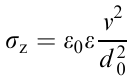
and the lateral strain ζz of the membrane having the Young's modulus Y (at the compression ζz<0), is
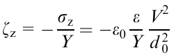
Equation (4) includes the ratio ε/Y, which can be referred to as the parameter of the efficiency of DEAPs because it depends only on the properties of the membrane. An increase in this ratio is indicative of an increase in the strain ζz of the DEA membrane upon the actuation.
The incompressibility makes it possible to derive the ratio for the areas and thicknesses of the membrane upon the actuation, assuming that the compression is equal with respect to the area and neglecting various edge effects. If S0 is the surface area of the non-actuated membrane and SV is the area of the membrane in the actuated state, S0d0= SVdV or SV/S0=d0/dV, i.e. to determine the area of the membrane with changing thickness and, on the contrary, determine the thickness of the membrane after its stretching. Thus, the stretching of a square membrane along each side by a factor of 4 (400%) leads to an increase in the area of the membrane by a factor of 16 (1600%), i.e., if the thickness of the initial membrane material is equal to 1 mm, the thickness of the membrane after the stretching will be 62.5 μm.
Despite the simplicity, this approach for calculations of the strained state of DEA membranes is still commonly used. This model was experimentally validated,107,108 and it was confirmed that the strain of the membrane is described by these equations with high accuracy up to (SV–S0)/S0⩽0.2 (20%).
Taking into account these assumptions, the strain is inversely proportional to the square of the thickness of the DEA membrane (4). When a DC, non-variable voltage is applied to electrodes of the DEA membrane, a decrease in the thickness of the membrane is accompanied by an increase in the electric field strength in the membrane. This positive feedback between the thinning of the DEA membrane and the field strength can lead to the electrical breakdown of the membrane or electromechanical instability. Therefore, it is necessary to find the optimal ratio of the actuation voltage to the thickness of the DEA membrane, as it was done, for example, in the study.109
It is also worth noting that in the above relations, the state of DEA membranes is derived in terms of the linear elastic Hooks model for the elastomer, but the non-linear viscoelastic behaviour of the DEA membrane, particularly, in the case of large strains, should also be taken into account in the calculations.
The modern theory of the stress-strain state of DEAs emerged from the theoretical publication.110 In this study, the author proposed a method for calculations of the electrostrictive deformable actuator taking into account not only the compressive stress from the surface electrodes but also the processes that occur during the compression in the bulk of the polymer based on the principle of the energy minimization. The approaches and methods for the modelling and simulation of the behaviour of actuator membranes under various strain loads are beyond the scope of this review. It should be noted that such calculations were performed in numerous studies, in which the behaviour of DEAs is simulated, the results of the calculations being in good agreement with the experimental data. Let us mention several studies109,111--113 as examples.
Pelrine et al.107,108 were the first to practically demonstrate the operation of actuators. They showed that the application of the voltage leads to an in-plane strain of the dielectric membrane by more than 200% for acrylic elastomers and by about 100% for silicone rubbers at a relatively high deformation velocity. These results have led to a surge of interest in DEAPs and DEAs as promising artificial muscles. Currently, great attention is paid to the design of new materials for DEA membranes and the construction of new DEA devices.9,19--21,114--117
Although the study107 was the pioneering one, the operation of DEA membranes (see Fig. 11) fabricated from different DEAPs was most clearly described in the study.108 The membranes shown in Fig. 11 were fabricated from the polydimethylsiloxane (PDMS) HS III (225 μm thick) by the spin-coating method followed by the prestrain and then fastened to holders; conductive grease served as the electrodes, the actuation voltage was up to 6 kV. The operation of circular and linear DEAs during actuation is presented in Fig. 11a and Fig. 11b, respectively.
![[{"id":"McnSaF4Aoq","type":"paragraph","data":{"text":"Schematic representation of the operation of DEA membranes during actuation: (<i>a</i>) circular DEA (the electrode diameter is 5 mm); (<i>b</i>) linear DEA.<sup>108</sup> Reproduced with the permission of The American Association for the Advancement of Science."}}]](/storage/images/resized/9kcfksZpys46QF3jHcgiNe2Rm7Zuf2kl6PH3ZH9s_xl.webp)
The results of the tests are presented in Table 2, which gives the type of the material, the degree of prestrain (see below), the relative changes in the electrode surface area during actuation and so on.108 The energy density is also included in the last column of Table 2. For any DEA, the energy density depends not only on the membrane material but also on the real DEA membrane thickness determined by the prestrain.
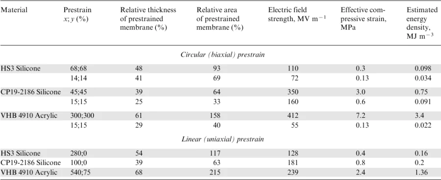
One cannot but pay attention to the tests of DEA membranes in the dynamic mode, i.e., under varying actuation voltage. High losses in acrylic elastomer do not allow it to operate in the dynamic mode well. Taking the membrane strain under a vibration excitation of 1 Hz as 100%, the strain in the acrylic membrane at 30--40 Hz will be as low as 50%,108 whereas the corresponding decrease in the strain in silicone rubber occurs only at the first tens of kilohertz.118,119
2.2. Actuator membranes. Materials and properties
Materials (DEAPs) with a wide range of Young's moduli combined with small mechanical losses, low electrical conductivity, high dielectric permittivity and a large elongation at break are required for DEA membranes.120
Currently, most of the developed DEAs are based on three types of membrane materials: polyurethanes, polyacrylates and silicone rubbers. Nevetheless, other materials, for example, fluorosilicone, poly(ethylene propylene), polybutadiene and polyisoprene, were also tested.107 Section 3 considers the state-of-the-art of the chemistry of DEAPs, methods and approaches for the optimization of the properties of these materials.
Polyurethanes used for DEAs exhibit relatively high Young s moduli and have a high dielectric permittivity (ε≈7.0 and higher). Unfortunately, DEAs based on polyurethanes exhibit low strains, which limits their usage as artificial muscles. However, attempts are made to design composites or copolymers based on polyurethanes with optimized characteristics.
Polyacrylates are apparently the most promising DEA materials for demonstrators and prototypes of DEA devices. The commercially available acrylic elastomer VHB is most commonly used. The Young's moduli and the dielectric permittivity of polyacrylates are generally lower compared to those of polyurethanes (e.g., for VHB, ε≈3.2), but the strains exhibited by polyacrylates being high. The linear actuation strains of DEAs with the prestrained acrylic elastomer VHB are higher than 380%;117 the area strains are up to 1000%.111,112 However, acrylates are characterized by high non-linearity, high viscoelastic losses and large residual strains, which complicates their use in finished items.
Dielectric elastomer actuators based on silicone elastomers occupy an intermediate position between polyurethanes and polyacrylic elastomers, being closer to the latter, but they exhibit lower viscoelastic losses, allowing them to operate sustainably, in particular, at higher frequencies. Their drawback is the relatively low dielectric permittivity, which requires higher actuation voltages compared to polyacrylates.
The above-mentioned polyacrylic DEA membranes, which are ready-made adhesive films VHB 4910 and VHB 4905 (the thickness is 1.0 and 0.5 mm, respectively). Silicone DEA membranes are generally fabricated from industrially available additive and condensation cured polymers, including Sylgard,121--123 Ecoflex and their blends, etc.124,125 Besides, commercially available silicone membranes based on the cured PDMS rubber Elastosil ® Film 2030 with different thickness (20–400 μm) are also widely used to fabricate DEAs. These membranes are employed as the reference compounds in studies of the new polysiloxane elastomer composites with an improved properties. In some cases, the specially synthesized laboratory silicones, for example, those with an increased dielectric permittivity, are utilized.
2.3. Actuator electrodes. Materials and methods of deposition
The main requirement for DEA electrodes is that they should be strained to the same extent as the DEA membrane without loss of performance (conductivity), i.e., the electrodes should have sufficient adhesion to the DEA material, exhibit robust and long-term performance, retain the integrity, possess satisfactory conductivity, etc. Materials for electrodes can be conventionally divided into carbon materials (CMs), such as carbon black, graphite, single-walled carbon nanotubes (SWCNTs), multiwalled carbon nanotubes (MWCNTs), their blends and materials without carbon materials (without CMs).126 Carbon materials can be deposited onto membranes in different forms: 1) in the dry form as a powder or a suspension in a volatile solvent, 2) as a conductive grease, i.e., as CMs dispersed in a viscous substance, for example, in gel, and 3) CMs as a filler in an elastomeric matrix. Dry CMs and conductive grease are most commonly used for electrodes in DEA demonstrators. Fig. 12 shows these three types of electrodes and the appearance of the electrodes deposited onto the membranes.127
![[{"id":"jk1A7Tsgpn","type":"paragraph","data":{"text":" Different carbon-based electrodes for DEAs and the appearance of the electrodes: (<i>a</i>) dry CMs, (<i>b</i>) conductive grease; (<i>c</i>) filler in an elastomeric matrix.<sup>127</sup> Reproduced with the permission of Springer Nature"}}]](/storage/images/resized/uWToBnpjLbWbFJGr0nFrCihxEE20Q9sORH5e5lw5_xl.webp)
Conductive greases used for electrodes are cheap and commercially available, they are easy to apply on the surface of the membrane, for example, with a brush and provide good conductivity even at high strains.127 The main drawback of the application of such grease electrodes in actuator prototypes is their dirtiness; they dirty everything they touch, and this surface becomes conductive.
Electrodes without CMs may be of different nature, e.g., electrodes as a thin metal foil.5,127,128 These electrodes are not widely used because of a low allowable strain and the appearance of fatigue cracks.
Ionic polymer gels (100 μm-thick polyacrylamide hydrogel containing NaCl as the electrolyte) were used as electrodes in the study.129 They are easily stretchable, perfectly transparent to light across the entire visible range and are capable of operation at frequencies above 10 kHz and voltages higher than 10 kV. Moreover, they are robust because the resistance of the electrode insignificantly changes with stretch.
A number of different types of carbon-free electrodes, which were employed to create prototypes or demonstrators of DEAs are listed below. This list is not comprehensive, but it shows the diversity of approaches for the fabrication of deformable electrodes:
- metal foil electrodes;5,127,128
- highly stretchable transparent electrodes based on ionic polymer gel;129
- liquid-phase metal electrodes based on gallium indium alloys as interlayer electrodes for multilayer actuators;130
- transparent electrodes based on silver nanowires;131
- shape-memory electrodes made of conductive materials to increase the stiffness of DEAs in the non-actuated state; when actuated via the application of high voltage to DEAs, the current heats and, correspondingly, softens the electrode, allowing the DEA membrane to be eaily deformed;132
- electrodes based on blends of conductive polymers and elastomers, which are deposited on the surface of the DEA membrane, for example, by spraying their solutions (polyaniline in a mixture with poly(styrene-co-ethylene-butylene-grafter-maleic anhydride) copolymer).133
Apart from pure carbon-based electrodes and carbon-free electrodes, composite stretchable electrodes based on PDMS or other polymers with carbon fillers are also often used.21,134--137
The procedure for the deposition of electrodes on the surface of the DEA membrane is determined by the actuator design and the choice of the electrode material. The following procedures are most commonly used to fabricate an electrode in a desired configuration on the membrane surface:
- spray coating through a stencil/shadow mask (Fig. 13a);
- stamping technique (Fig. 13b);
- inkjet printing provided that the viscosity (and other parameters) of the deposited material is suitable for printing (Fig. 13c).
- application of a pattern on both sides of the membrane with a paintbrush (see Fig. 14).
![[{"id":"2Tb74eYan4","type":"paragraph","data":{"text":"Different methods to pattern electrodes in a desired configuration: (<i>a</i>) shadow masking; (<i>b</i>) stamping; (<i>c</i>) inkjetprinting.<sup>127</sup> Reproduced with the permission of Springer Nature"}}]](/storage/images/resized/Z6znRbftjRv5Ui7MhgkFJd0XQP8i5rkVm3UVMYWw_xl.webp)
![[{"id":"AAqNyoVXgX","type":"paragraph","data":{"text":"Schematic of the process to pattern a carbon nanotube (CNT) electrode with a brush through a shadow mask.<sup>140</sup> Reproduced with the permission of MDPI."}}]](/storage/images/resized/Jx3NLeovk2aSp2ElWmBHK7YY2v0uJPK0i0bAWGai_xl.webp)
More complex, sometimes multistep, methods are utilized, for example, to deposit a blend of poly(alkylthiophene) and multiwalled CNTs onto a membrane (3 μm) using the Langmuir--Blodgett method,138 the patterning of an electrode on the substrate followed by its transfer to the plasma-activated membrane and the dissolution of the substrate,139 etc.
In the recent study,140 the methods for the deposition of electrodes returned back to the beginning of the history of DEAs, providing clear evidence that electrodes for demonstrators and prototypes can be painted with a brush following simple rules and with sufficient care.
The reliability and durability of electrodes were comprehensively tested for several types of carbon-based electrodes. The aging of carbon-based electrodes, which were applied on a DEA membrane using different techniques, was studied by de Saint-Aubin et al.141 A 20 μm-thick Elastosil 2030 membrane was employed (the active area of DEA was 10 mm2). The tests were performed with the strain area of 5%. A complex interrupted test cycle and the drive frequency of 50 Hz made it possible to control the changes in the residual deformation of the DEA membrane.141
It is worth noting that the resistance of the electrode is not really important for the DEA performance, because the electrode just has to be continuous to provide the operation of the DEA membrane as a planar capacitor; however, the change in the resistivity of the electrode is the robustness indicator, i.e., the indicator of the durability of the actuator.
Table 3 presents the results of the tests of different types of carbon-based electrodes and the tests for the robustness, i.e., the number of actuation cycles before the electrode degrades and the loss in adhesion to the DEA membrane occurs.141
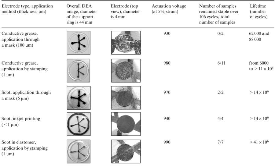
The method of the deposition of electrodes is determined by the ease of application and the robustness of electrodes for DEAs. Thus, the ease of painting of electrodes with a brush, as was described in the study,140 is sufficient for DEA demonstrators, whereas the reliability and durability are the most important criteria for mass production. The optimal versions141 are given in the lower rows of Table 3. Carbon in an elastomeric matrix is the most preferable material; it can be cycled for up to 40 million cycles and is characterized by the minimum change in the electrode resistance.
The robustness of electrodes, that is the resistance and the residual deformation as a function of the number of actuation cycles of DEAs, was also tested (Fig. 15). An increase in the resistance and in the residual deformation serve as indicators of the degradation of the actuator electrodes.
![[{"id":"T87JBD3W1P","type":"paragraph","data":{"text":"Aging tests of carbon-based electrodes; (<i>a</i>) the resistance (kΩ) and (<i>b</i>) the residual deformation of the membrane versus the number of actuation cycles of DEAs.<sup>141</sup> Reproduced with the permission of IOP Publishing"}}]](/storage/images/resized/GXK1t2Ca0Cl6dqAMvzD9AW8exxIf2MTXTfgcw55I_xl.webp)
Using the data presented in Fig. 15 or similar data (in the case of the known electrode design), one can estimate the durability of DEAs, determine the criteria for the replacement and so on. It was also noted that at 20% strain, the lifetime of most types of electrodes reduces to a few thousand cycles.
2.4. Equipment for fabrication and operation of dielectric elastomer actuators
2.4.1. Prestretching devices
The manufacturing of a free polymer membrane of an actuator with a very small thickness, say, below 10 μm is impractical, and even the handling of a 15 μm-thick membrane is tricky. Therefore, dielectric membranes with a small thickness, for example of 3 μm as in the study,107 are prepared by a layer-by-layer deposition technique immediately in the proces of fabrication of a multilayer actuator. For highly elastic polymers, the thickness of the free membrane is controlled using prestretching, DEA used to be fabricated from the prestretched membrane. Thus, after the prestretching of a 1 mm-thick square membrane four times along each side, the thickness reduces to 62.5 μm (see Section 2.1). A series of problems of the performance of DEA membranes are also solved by the prestretching. Thus, it prevents mechanical instability of DEA membranes, such as the wrinkling and bending of the actuated membrane, reduces the actuation voltage.
Fig. 16 presents two typical devices for prestretching DEA membranes.113,142 A biaxial stretching device is shown in Fig. 16a.113 Initially, the film is stretched in the horizontal direction and then the clips stretch the film in the vertical direction. Fig. 16a presents the polyacrylic membrane VHB4910 prestrained by 400% in each direction. An example of a radial stretcher is shown in Fig. 16b.142 A disc-like membrane is radially stretched by moving clips, which hold the circumference of the disc-like membrane (in the device shown in Fig. 16b, there are 16 clips). In the cited study, the membrane VHB F9473PC was used; the strain reached 250%. This type of stretching is most commonly applied to fabricate circular DEAs. It should be noted that in all the methods used to prestretch DEA membranes, the critical factors are inhomogeneity and defects of the initial film and also the non-uniformity of the film in thickness, which are the key parameters of the initial material for DEA membranes.
![[{"id":"iMR9I3IJ-T","type":"paragraph","data":{"text":"Devices for pre-stretching DEA membranes: (a) a biaxial stretching device,<sup>113</sup> (b) a radial stretcher.<sup>142</sup> Reproduced with the permission of MDPI<sup>113</sup> and IOP Publishing<sup>142</sup>"}}]](/storage/images/resized/Ka6TA90ipgLeuxTy1rGMMzExSh2MdZTCbsZ3aAQl_xl.webp)
2.4.2. Devices for the fabrication of multilayer DEA membranes
Apart from mechanical equipment for assembling usual DEA membranes to form stacks or layers coated with electrodes, multilayer DEA membranes are generally fabricated by the spin-coating method through the successive layer-by-layer casting of membranes and deposition of electrodes followed by the removal of the finished sandwich and cutting of DEAs to desired shape and size.
The fabrication of a multilayer DEA membrane was descried in detail in the study.143 First, mixed two-component silicone rubber is spread on a rotating substrate, a thin polymer layer is produced by spinning and then cured; the thickness of the resulting layer is 5--10 μm. Then 3--5 μm-thick carbon-based electrodes are patterned through a shadow mask, the patterns are somewhat different for odd and event layers. The automated device for the membrane fabrication was described in the study.143
It is worth noting that polymers produced by different curing methods can be used in multilayer DEAs. The method for the deposition of interlayer electrodes can also be varied. The main advantage of multilayer DEA membranes is a low actuation voltage (200--600 V). The operation with a voltage lower than 600 V does not require a specialized high-voltage equipment, thereby making it possible to employ standard laboratory voltage sources and electronic components. Besides, actuator membranes fabricated using by these techniques do not require additional prestretching. However, since the fabrication of multilayer membranes is labour- and time-consuming, it is not commonly used.
2.4.3. High-voltage sources
It is reasonable to consider controlled high-voltage sources for the actuation of DEAs as a part of DEAs, although in most cases they are separate units or electronic blocks. The resistance of the DEA membrane is high and the DC current does not flow through the membrane even when it is actuated. This allows the use of high-voltage sources with a minimum output current, i.e., with a small power and, consequently, with a small size. Generally, laboratory 2--3-kV high-voltage sources are applied for this purpose. However, there are also examples of the employment of sources with a higher voltage of 7 kV or even 15 kV). Voltage sources with a voltage of up to 5 kV and a weight of up to 5 g are commercially available. The manufacturing of high-voltage power inverters up to hundred volts powered by a 3.7 V watch battery with a weight smaller than 1 g was described in the study.144 There are other related studies (see, for example, the publications145,146).
The cyclic actuation of DEAs requires a high DC voltage. In these cases, a scheme consisting of a signal generator and a high-voltage output amplifier, which has a wide bandwidth to operate at a specified frequency, is used. The optimization of the modulated voltage waveform under cyclic loading was described in the study.147 In this case, DEA serves as a component of the generator or additional coupled loading circuits,148 which improves the performance of a voltage source–DEA membrane system.
3. Materials for DEA membranes
The selection of the material for a DEA membrane is a key problem in the design of DEAs responsible for the characteristics of the device. As follows from Section 2, these materials should have a complex of properties, such as high dielectric permittivity, high electrical breakdown strength, low Young's modulus, high deformability, fast electrical response and cyclic load resistance.
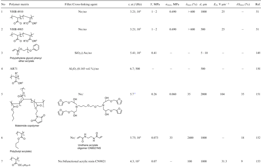
Among DEAPs for the fabrication of biomimetic artificial muscles, polyacrylates, polyurethanes and silicones are worth mentioning. The materials considered in this Section of the review are listed in Table 4, Table 5 and Table 6, respectively, for polyacrylates, polyurethanes and polysiloxanes with dispersed fillers. The composition and properties of DEAPs based on chemically modified PDMS composites are presented in Table 7.
3.1 Polyacrylates
Polyacrylates are thermoplastic polymers of the general formula –[CH2CH(COOR)]n– or –[CH2C(CH3)(COOR)]n–, which are synthesized via polymerization of acrylates or methacrylates and copolymerization with other monomers containing an unsaturated bond such as the styrene/acrylate copolymer –[CH2CH(COOR)]n–[CH2CHC6H5]m– or the ethylene/acrylate copolymer –[CH2CH(COOR)]n–[CH2CH2]m–.
A class of commercially available polyacrylate elastomers, VHB membranes, were widely used to fabricate DEA devices.111,112,117,191--201 The VHB adhesive films show relatively high dielectric permittivity ε=3.21 at 1 kHz and large linear strains up to 600% (Table 4, Nos 1 and 2).108,191 Due to a high elongation at break, films with a large thickness (0.5–1 mm) can be utilized using prestretching to decrease the thickness of the DEAP membrane to the required value. A relatively high electric field strength (up to 100 V μm–1) is required for the actuation of these membranes. Large viscoelastic losses and the presence of residual strains significantly complicate the use of acrylic membranes in DEAs. Besides, the operation of DEAs based on these membranes is temperature-dependent, and the optimal temperatures are in a rather narrow range from 0 to 20 °C, which limits the potential fields of application of DEA devices with a polyacrylate membrane.192
Various methods for the fabrication of polyacrylate elastomers, alternative to commercial elastomers, with improved electromechanical characteristics are described in the literature. These methods can be divided into two large groups.
In one group of methods, the properties of polyacrylate membranes are controlled via the structure and properties of the components, such as cross-linkers, modifying additives, in situ UV-induced curing of monomers. In particular, it was reported149 that the photopolymerization of poly(ethylene glycol) phenyl ether acrylate using gold-capped SiO2 Janus particles as the filler leads to a fourfold increase in the dielectric permittivity to ε =5.4, a decrease in the Young's modulus from 1.7 to 0.4 MPa and, correspondingly, to 24 times enhanced response of the membrane compared to the unfilled film (Table 4, No. 3). The introduction of unmodified SiO2 particles has no significant effect on these characteristics. Composites based on the commercial acrylic rubber AR71 and Al2O3 particles (Table 4, No. 4) show an increase in the dielectric permittivity to ε =6.7 at the filler content of 14.4 vol.%; however, the Young s modulus of these composites increases by a factor of 10.150
In the study,151 new acrylate elastomers were prepared by the photocopolymerization of n-butyl acrylate, diethylene glycol ethyl ether acrylate and acrylate containing furan-maleimide Diels--Alder adduct moieties. The Young's modulus of these elastomers can be controlled in the range of 0.17–0.52 MPa via the thermally induced reversible Diels--Alder reaction (Table 4, No. 5). Devices based on these membranes can be operated in both high strain mode (35% at 65 V μm-1) and high force output mode (0.55 MPa at 104 V μm–1).
The polymerization of n-butyl acrylate using a large-molecular-weight urethane acrylate cross-linker with flexible polyether diol and aliphatic diisocyanate segments instead of conventional small-molecular-weight cross-linkers resulted in the fabrication of a dielectric elastomer, which possesses low Y≈73 kPa, high reversible toughness (expansion up to 2400%), low mechanical loss and increased ε =5.75 at 1 kHz (Table 4, No. 6). It should be noted that the device based on this material is characterized by a large actuation strain at high actuation voltage (118% at 70 V μm–1).152
A new type of acrylic dielectric elastomers was proposed in the study.153 It was synthesized by UV curing of poly(lauryl acrylate) and the bifunctional acrylic resin CN9021 (Sartomer Arkema Group, France) as the cross-linker in the presence of 2-hydroxy-2-methylphenylacetone as the photoinitiator (Table 4, No. 7). The investigation of the mechanical properties of the resulting films showed that the mechanical losses significantly decreased with increasing amount of the cross-linking agent and, although the Young's modulus increases, it remains small, making it possible to achieve significant strains under the actuation. The actuation test demonstrated that the best film exhibits 9% actuation area strain without prestretching under the actuating electric field of 11 V μm–1, which is much higher compared to VHBTM 4910. The drawback of this material is that the actuation of DEAs causes the membrane creep, which gradually decreases as the frequency of the actuation voltage gradually increases.
Therefore, the control of the properties of a polymer membrane through the structures of the initial components and their ratio provides an efficient tool to increase the actuation strains of the membrane and, in some cases, to decrease the creep effect, the actuapfvtytion voltage of DEA remaining rather high.
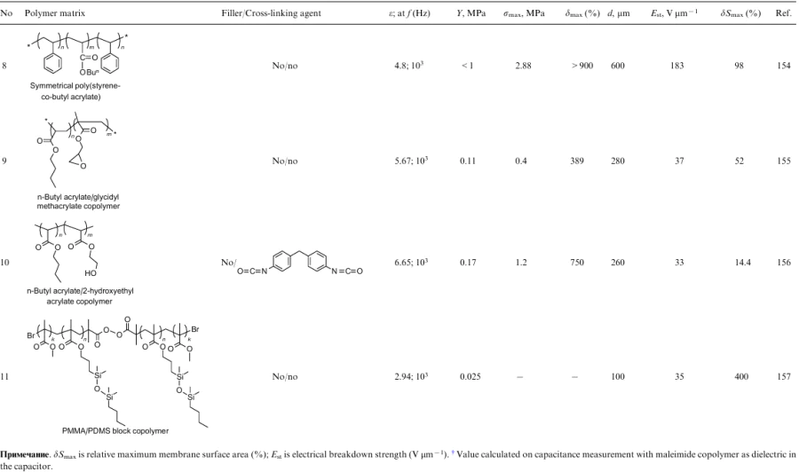
Another group of methods for polyacrylate material fabrication is based on the preliminary molecular design of a polymeric macromolecule with the required structure followed by its curing. Thus, the first synthesis of the ABA triblock copolymer, where A is the polystyrene block and B is the poly(n-butyl acrylate) block, was described in the study154 (Table 4, No. 8). This thermoplastic copolymer is characterized by higher dielectric permittivity and lower viscoelastic losses and exhibits better dynamic performance compared to the commercial polyacrylate VHB 4910.
A series of n-butyl acrylate--2,3-epoxypropyl methacrylate copolymers with different monomer ratios were synthesized by the atom transfer radical polymerization (ATRP)155 (Table 4, No. 9). The subsequent heating of these copolymers at 80 °C for 12 h afforded a series of elastomeric films with ε=6 and Y=0.1--0.41 MPa depending on the ratio of monomer units. Dielectric elastomer actuators based on the synthesized elastomers are characterized by an area strain of the membrane of 50% at 20 V μm–1, which is 4 times higher compared to the commercial VHB4910. The slope of dielectric losses was smaller than 0.5 at room temperature.
A DEA membrane was synthesized by the ATRP method from the n-butyl acrylate--2-hydroxyethyl acrylate copolymer156 (Table 4, No. 10). Films of the composite were prepared by the reaction of the synthesized polymer with different amounts of diphenyl methane diisocyanate. The resulting DEAPs are characterized by a high actuation area strain (14.4%) at an electric field of 15.2 V μm–1 without prestretching, which is also higher compared to that for acrylic VHB 4910.
The studies157,202 hold a special place in the design of DEA materials possessing low moduli based on acrylate and siloxane copolymers. The authors developed a design platform, allowing the fine tuning of the mechanical characteristics of the material by controlling the molecular parameters of the network. Thus, thermoplastic elastomers, linear ABA triblock copolymers, which differ in the degree of polymerization of the A block from 145 to 867, were synthesized. Theses copolymers are composed of the poly(methyl methacrylate) linear block A and the brush block B with a polymethacrylate backbone, characterized by the degree of polymerization 884, and a dimethylsiloxane side chain with a length of 14 units (Table 4, No. 11). The materials synthesized based on these copolymers exhibit a low Young's modulus of 1--10 kPa and high strain at low voltage (Fig. 17). The best characteristics of DEAs, such as the fivefold strain at a low actuation voltage of about 1 V μm–1, were achieved for a membrane with a degree of polymerization of the A block equal to 438, without prestretching and with a membrane thickness of 1 mm.
![[{"id":"uvkdQrEOkE","type":"paragraph","data":{"text":"Photographs illustrating giant strains of a free-standing membrane made of the thermoplastic bottle-brush triblock copolymer observed in circular DEA at an actuation voltage of up to 3.5 kV.<sup>202</sup> Reproduced with the permission of John Wiley and Sons"}}]](/storage/images/resized/lGT0IStdC1WLM5lKxE2rpPOU08fjUDDZh9VVEIHU_xl.webp)
Therefore, the molecular design of polymeric macromolecules makes it possible to significantly decrease the actuation voltage for polyacrylate membranes; the record values being achieved when using acrylate-siloxane copolymers.
3.2. Polyurethanes
Polyurethanes are polymers containing urethane groups –HN–C(O)–O–, which are synthesized by the reactions between isocyanates with different structures and hydroxyl-containing, most often polyester, oligomers. The chemical crosslinking of polyurethanes is accomplished using tri- and tetrafunctional monomers. Physical networks can be formed via hydrogen bonding between urethane moieties and through the crystallization of polyester segments. The physical networks result in high breakdown strength characteristics of these polymers and a high Young's modulus, which complicates their use in DEAs because of the necessity of applying high actuation voltage.
Meanwhile, the polar nature of urethane moieties is responsible for higher dielectric permittivity of these polymers compared to acrylates and silicones. The dielectric permittivity is a linear function of the concentration of urethane groups and varies from 7 to 12 for commercially available polyurethanes.192 Besides, polyurethanes can be molten, and then thin films with a thickness smaller than 50 m can be prepared from these melts, which can compensate the high Young s modulus of polyurethanes.159,203
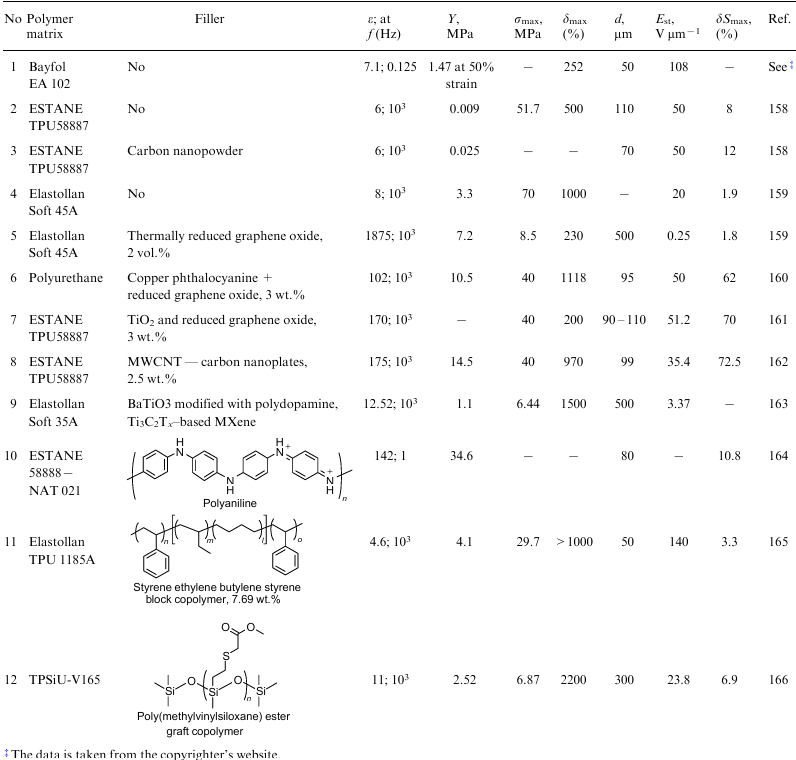
The commercially available polyurethane film Bayfol EA 102 is characterized by the dielectric permittivity ε=7.1, the electrical breakdown strength up to 130 V μm–1 and Y=1.44 MPa at 50% strain (Table 5, No. 1). An undeniable advantage of this film over acrylic films VHB is 20 times lower viscoelastic loss; however, unfortunately, high moisture sensitivity of polyurethanes due to their high polarity leads to significant leakage currents.204
The electromechanical potential of the commercially available polyurethane ESTANE 58000 TPU was improved by incorporating carbon nanopowder with a particle size of 30 nm in a polymer matrix (Table 5, Nos 2 and 3).158 The elastomeric films with a thickness of about 70 μm were prepared. It was shown that DEAs based on these composites have an actuation strain up to 8% at 8 V μm–1.
A dielectric elastomer based on the polyurethane TPU Elastollan Soft 45A and thermally reduced graphene oxide was described in the study159 (Table 5, No. 4 and 5). The dielectric permittivity of the material sharply increased compared to unfilled polyurethane (ε=1875 versus ε=7) by adding 2 vol.% of graphene oxide; the Young s modulus increased from 3 to 7 MPa, and the conductivity increased by four orders of magnitude to 10–7 S cm–1. The actuation strain of the DEA membrane based on this material can reach 1.8% at a low electric field of 0.25 V μm–1 (the strain of unfilled polyurethane is 0.1%). The incorporation of polyethylene glycol with a molecular weight of 600 into composites has a plasticizing effect, the Young's modulus decreases by a factor of 6 and the dielectric permittivity also decreases with the retention of high conductivity.177 In this case, the electrical breakdown strength increases, but it is not higher than 10 V μm–1
The use of graphene oxide functionalized with copper phthalocyanine as a filler of polyurethane160 also leads to an increase in the strain (by a factor of 2), the dielectric permittivity and the breakdown strength and a decrease in the Young's modulus compared to the composite filled with unmodified graphene oxide (Table 5, No. 6). The use of a blend of graphene oxide and titanium oxide instead of pure reduced graphene oxide leads to an increase in the maximum strain of the film elastomer by a factor of 1.8, to 72.4% at 38.7 V μm–1 (Table 5, No. 7).161
The polyurethane elastomer ESTANE 58000 TPU was used to compare the effect of MWCNTs, carbon nanoplates and a MWCNT/carbon nanoplate blend on the dielectric and mechanical characteristics of films.162 The dielectric permittivity of composites with fillers increases proportionally with the filler amount. The breakdown strength and the Young s modulus of MWCNT-based composites are higher compared to other composites. The incorporation of any filler leads to an increase in the actuation strain of the composites. However, the best result was achieved for the MWCNT/ carbon nanoplate blend; the strain of this blend was 72% at 35 V μm–1, whereas the strain for unfilled polyurethane was at most 29% at 38 V μm–1 (Table 5, No. 8).
The study163 described the synthesis of composites of the thermoplastic polyurethane TPU Elastollan Soft 35A filled with barium titanate nanofibres, the surface of which was modified by polydopamine, and a 2D material (MXene) based on titanium carbide (Table 5, No. 9). The incorporation of modified barium titanate leads to an increase in the dielectric permittivity, low dielectric losses and the high Young's modulus of the composites. The addition of 2D titanium carbide results in a further increase in the dielectric permittivity, but this also leads to an increase in dielectric losses and a decrease in the Young's modulus of the composites. A combination of these fillers made it possible to increase the dielectric permittivity with the retention of low dielectric losses and a decrease in the Young's moduli.
The incorporation of polyaniline into polyurethanes164 also leads to an increase in the dielectric permittivity to ε=142 (Table 5, No. 9). The maximum strain of the membrane is 10.8% at low electric fields of 4.5 V mm–1.
In a recent study, the properties of polyurethane were improved by the addition of a styrene–ethylene–butylene–styrene copolymer (Table 5, No. 11).165 In this case, the Young's modulus reduced by half compared to unfilled polyurethane (to 2.4 MPa), the dielectric permittivity decreased to ε =4.6 and the electrical breakdown strength increased to 118 V μm–1. The maximum actuation strain of this material at 80 V μm–1 was 4.7%, which is 2.5 times higher compared to that of unfilled polyurethane.
The incorporation of polymethylvinylsiloxane grafted by methyl thioglycolate into the thermoplastic polyurethane TPSiU-V165 was accomplished in the study166 (Table 5, No. 12). The Young's moduli of the synthesized composites significantly decreased compared to the initial polyurethane (2.52 versus 3.78 MPa), the dielectric permittivity increased from ε=4 to ε=11 at 1 kHz and the electrical breakthrough strength decreased from 45 to 24 V μm–1. The maximum strain was 6.9% without prestretching.
Therefore, the analysis of the literature data shows that the majority of studies on the application of polyurethanes as DEA membranes were aimed at preparing composites filled with carbon particles, which allow the control of the electromechanical characteristics of membranes, in particular, make it possible to increase the dielectric permittivity and the maximum strain of the material; however, the actuation voltage remains rather high.
3.3. Polysiloxanes
Polysiloxanes are the most promising materials for DEAs. Unlike polyacrylates, polydimethylsiloxanes (PDMS) –[(CH3)2SiO]n– can operate at high frequencies with small losses, have stable electrical and mechanical properties and exhibit a fast electrical response.192 As opposed to thermoplastic polyurethanes, PDMS shows moderate elongations, low Young's moduli and rather high breakdown strengths. Moreover, PDMS is operated at a wide temperature range, environmentally safe, biologically inert and processable. These properties determine the interest towards PDMS materials as electromechanical actuators, force sensors and flexible electronics. Because of low dielectric permittivity of PDMS (ε =2.7–3.2), the required driving voltages become close to the dielectric breakdown strength (100 V μm–1 and higher), thereby limiting the scope of applications.205
A number of papers and original studies discuss the design of silicone-based DEAs, as well as the issues related to its manufacturing problems.206--209
The state-of-the-art of the silicone chemistry ensures a vast diversity of research on the (i) modification of PDMS and (ii) the preparation of composites with required characteristics for DEA.210--212 Whilst the latter involves the incorporation of disperse fillers into the PDMS matrix, the former group relies on the fabrication of chemically modified polar siloxanes with improved dielectric permittivity. In addition, controlled mechanical properties were have been achieved through the highly stretchable composites, the synthesis of bottle-brush polymers for highly soft composites, the fabrication of liquid fillers for interpenetrating networks, etc.
3.3.1. Polydimethylsiloxane composites with dispersed fillers
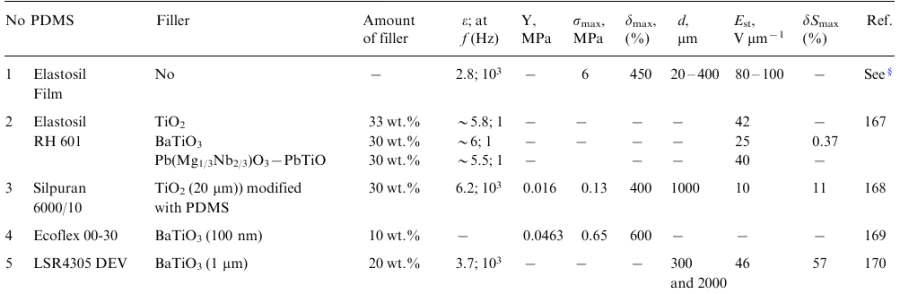
The first report on the introduction of fillers with high dielectric permittivity, such as titanium dioxide TiO2, barium titanate BaTiO3 and lead magnesium niobate-lead titanate Pb(Mg1/3Nb2/3)O3--PbTiO3, into polymers was published by Szabo et al.167 (Table 6, Nos. 1 and 2). The authors studied the effect of the filler concentration in the PDMS Elastosil RH601 A/B on the dielectric and mechanical characteristics of the composite at a frequency of 1 Hz.
It was found that an increase in the filler concentration leads to an increase in the Young's modulus and the dielectric permittivity of the composites. However, this effect is significant only at a high filling content from 30 to 70 wt.%, while the type of the filler has no significant effect on these characteristics.
The PDMS Silpuran 6000/10 composites containing TiO2 particles (20 μm), which was preliminary functionalized with low-molecular-weight PDMS, demonstrated an increase in the linear strain compared to pure PDMS at the filler concentrations of 5 and 10 wt.% at an electric field of 80 V μm–1 (Table 6, No. 3). This was attributed to an increase in the dielectric permittivity of these composites. A decrease in the strain as the filler concentration further increases is due to an increase in the Young's modulus.168 It should be emphasized that the slope of the loss remains almost unchanged compared to pure PDMS up to 30 wt.% of the filler, which is indicative of the absence of the effect of TiO2 on the viscoelastic properties of the material. The filling of PDMS composites with TiO2 up to 12 wt.% has not effect on the breakdown strength.213,214
The introduction of BaTiO3 nanoparticles with a size of 100 nm into PDMSs up to 10 wt.% leads to an increase in the Young's modulus (Table 6, No. 4).169 A further increase in the filler content facilitates the agglomeration of particles in the composite and, at a filler content >10 wt.%, results in a decrease in the Young's modulus. The filling of PDMSs with BaTiO3 particles with a size of 1 μm leads to an increase in the dielectric permittivity of the composite to ε=6, but the effect is achieved only at high filling factors (50 wt.%) (Table 6, No. 5).170 At low frequencies, the slope of the dielectric loss increases. The minimum Young's modulus of these composites was observed at the equi-biaxial stretch ratio of 1.6. The maximum strain of 57%, achieved by DEAs at an applied electric field of 46 V μm–1, was found for the composite with 20 wt.% filler content. A further increase in the degree of filling led to a decrease in the strain, which was also attributed to the particle aggregation.
The necessity of a high degree of filling of the polymer matrix with BaTiO3 particles is in good agreement with the data obtained for the filling of other polymers.215,216 However, in this case an increase in the dielectric permittivity does not allow the reduction of the actuation voltage, in particular due to a decrease in the electrical breakdown strength.
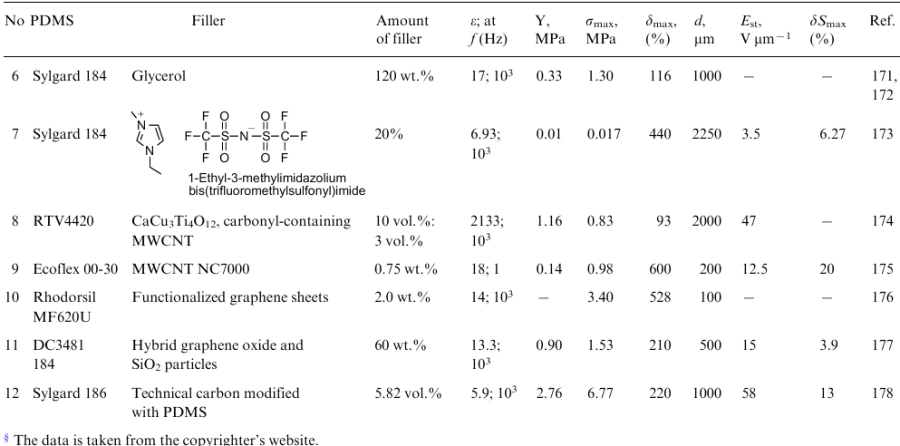
The introduction of polar liquids, like solid polar or electrically conductive fillers, allows the control of the dielectric and mechanical properties of composites. Glycerol was used as the polar liquid in the studies.171,172 The introduction of 37 wt.% glycerol into the PDMS Sylgard 184 made it possible to achieve ε=12 for the composite, whereas the conductivity remained rather low (10–13 S cm–1), and the Young's modulus decreased to 0.3 MPa (Table 6, No. 6). These materials are promising for DEAs. However, electromechanical studies were not conducted and, consequently, the mechanical stability of the composites cannot be evaluated.
The addition of 20 vol.% 1-ethyl-3-methylimidazolium bis(trifluoromethylsulfonyl)imide as the ionic liquid to the PDMS Sylgard 184 matrix173 leads to an increase in the dielectric permittivity to ε=7 and a decrease in the Young's modulus to 10 kPa (Table 6, No. 7). The electrical breakdown strength of these composites decreases to 15 V μm–1. An increase in the linear strain of the composite is 6.5% at nominal electric fields of merely 4 V μm–1.
The introduction of conductive carbon fillers, such as technical carbon, graphene, graphene oxide, CNTs, into the matrix is another method commonly used to enhance the dielectric permittivity. However, the use of such fillers to prepare dielectric elastomers is limited by the critical filler concentration known as the percolation threshold. The incorporation of CNTs into PDMSs at low concentrations (1–5 wt.%) makes it possible to increase the dielectric permittivity, with the Young's modulus remaining unchanged or decreasing, but this leads to a significant decrease in the electrical breakdown strength of the composites compared to PDMS and an increase in the conductivity when approaching the percolation threshold.217--220
As opposed to composites with MWCNTs, the embedding of covalently bonded calcium copper titanates (CaCu3Ti4O12) with carbonyl-containing MWCNTs into PDMS composites results in an increase in the dielectric permittivity to ε=2133 at 1 kHz with the retention of low dielectric losses, as small as 0.19 (Fig. 18) (Table 6, No. 8).174 The tensile strength of these composites approaches 1.12 MPa, and the Young's modulus increases to 1.16 MPa.
![[{"id":"wJdwvqMZGf","type":"paragraph","data":{"text":"Comparison (<i>a</i>) of the dielectric permittivity and (<i>b</i>) the dielectric loss at 1 kHz for PDMS, CaCu<sub>3</sub>Ti<sub>4</sub>O<sub>12</sub> (10 vol.%)/PDMS (CCTO/PDMS), MWCNTs (2 vol.%)/PDMS (MWCNTs/PDMS) and CaCu<sub>3</sub>Ti<sub>4</sub>O<sub>12</sub> (10 vol.%)@MWCNTs PDMS (3 vol.%)/(CCTO@MWCNTs/PDMS).<sup>174</sup> Reproduced with the permission of Royal Society of Chemistry"}}]](/storage/images/resized/E1r9zZyxgFzHJFt1HWqKxFyEEhBGAim0R5V8lhyy_xl.webp)
In the study,175 11-layer composites with a total thickness of 200 μm were prepared by the sequential deposition of the layers of PDMS Ecoflex 00-30 and MWCNTs (Nanocyl NC7000)/PDMS blend (Fig. 19).
![[{"id":"fgkwCyrWxl","type":"paragraph","data":{"text":"Schematic of the assembly process for multilayer elastomer composites.<sup>175</sup> Reproduced with the permission of Elsevier"}}]](/storage/images/resized/VJGtMNAUGEOynAXkrzeugDwS8V5LPwH2g5LPL93Z_xl.webp)
It was found that the dielectric constant e of the composites sharply increases when the MWCNT content in the PDMS/MWCNT layer increases from 0.5 to 0.75 wt.%; for 1 wt.%, ε is 22 (Table 6, No. 9). The Young's modulus of the composites increases twofold compared to pure PDMS, from 0.08 to 0.15 MPa, but the electromechanical sensitivity is 5.5 times higher compared to PDMS. The electrical breakdown strength of the composites decreases with increasing MWCNT content and is 9.5 V μm–1 for 1 wt.%. A comparison of the strains of the initial PDMS and the multilayer composites at an applied filed of 8 V μm–1 demonstrates an eightfold increase. The sample with 0.75 wt.% MWCNT content in the PDMS/ MWCNT layer showed the highest and stable strain over a total of 100 cycles (20.3% at 12.5 V μm–1) at an applied voltage without any prestretching.
The dielectric and mechanical properties of composites based on PDMSs and functionalized graphene sheets (FGSs), which were prepared by the thermal reduction of graphene oxide, were investigated in the study176 (Table 6, No. 10). It was found that the dielectric permittivity of the sample containing 2 wt.% FGSs increased by a factor of 10 compared to unfilled PDMS, with low dielectric loss and good mechanical properties being retained.
The introduction of graphene oxide-encapsulated silica hybrids (GO@SiO2) into PDMS177 made it possible to simultaneously increase the dielectric permittivity from ε=3.2 for PDMS to ε=13.3 for the composite at 1 kHz and improve the mechanical properties (Table 6, No. 11). The dielectric loss remained rather low (<0.2 at 1 kHz). Although the filled composite had a higher Young's modulus, the simultaneous increase in the dielectric permittivity of the composite led to a higher actuated strain at an applied electric field (3.5% at 10 V μm–1) compared to the initial PDMS (0.58% at 10 V μm–1).
The introduction of technical carbon particles into PDMS Sylgard 186, graft modified with monohydroxyl-containing PDMS,178 at 5.82 vol.% filler content leads to an increase in the Young's modulus and the dielectric permittivity to 2.76 MPa and ε=5.9, respectively (Table 6, No. 12). The introduction of modified technical carbon results in an approximately twofold increase in the electrical breakdown strength of the composite compared to the unmodified sample (from 34.5 to 63 V μm–1). The membrane actuated by a low electric field of 7.14 V μm–1 showed a 2.8-fold increase in the surface area compared to pure PDMS.
In general, the introduction of dispersed particles leads to an increase in the dielectric permittivity of siloxane elastomers and electromechanical sensitivity. However, all studies were performed using rather thick samples, from 500 μm to 2 mm, which require high applied voltages (>1 kV), thereby, limiting their application for the fabrication of artificial muscles.
3.3.2. Chemical modification of PDMS and elastomers on its basis with polar groups
The chemical modification of siloxanes with polar groups leads to an increase in the permittivity and also makes it possible to fabricate membranes with a low thickness (100 μm), which allows the decrease in an electrical voltage for their actuation. The fabrication of PDMS composites containing polar groups involves the premodification of one component, either the polymer or the cross-linker, followed by curing, which makes it possible to control the properties of the composite at the molecular level. Moreover, polar groups can be grafted to the matrix directly during the curing process.
Numerous investigations of polysiloxane DEA concerned with the chemical modification of PDMS and components with polar groups (alkylthio,221,222 fluoroalkyl,136,183 chloroalkyl or aryl,180,183,185 thioacetyl,181,223 nitrile,179,181,224--229 nitroalkyl,181 nitroaryl,182,184,230 sulfonyl,231 azobenzene,232 other groups181,233,234), the study of its effect on the dielectric and mechanical characteristics of modified PDMS and PDMS composites, the manufacturing of devices and evaluation of their performance.
One of the key problems of PDMS modification with polar groups is that an increase in the dielectric permittivity occurs along with a decrease in the backbone flexibility depending on the length of the spacer between the backbone and the polar group. As a consequence, the glass transition temperature increases and elastic deformations decrease, which ultimately narrows the operating temperature range and leads to a decrease in the strain of DEA.
The effect of a wide range of polar groups (Fig. 20) on the dielectric characteristics and the glass transition temperature of PDMS was comprehensively studied in 2021.223 This reseach revealed the most promising polar groups for modification. A series of PDMSs with certain molecular-weight characteristics and a specified number of vinyl groups were synthesized. Then polar groups were grafted to these polymers via the thiol-ene reaction. The analysis of the correlations of the dielectric permittivity of the synthesized polymers with the glass transition temperature and the conductivity (see Fig. 20) demonstrated that PDMSs modified with methylsulfonyl (6, the numbering according to Fig. 20), 2--oxopyrrolidinyl (8), N,N-dimethylpropylamide (9) and cyanopropyl (13) groups are most promising for use as dielectric elastomers because these elastomers show high dielectric permittivity (ε=7-8 at 20 mol.% content of siloxane units with polar groups, ε=20–22 at 100 mol.%) with increasing glass transition temperature from ca. –100 to –20 °C in the case of (6) and to –40 and –50 ºC for (8, 9, 13) and with an insignificant change in the conductivity.
![[{"id":"lyAayeKh0z","type":"paragraph","data":{"text":"Dielectric permittivity at 10 kHz and 20 °C versus the glass transition temperature (<i>a</i>) and the conductivity (<i>b</i>) for polymers modified with polar groups (1-13).<sup>223</sup> Reproduced with the permission of American Chemical Society"}}]](/storage/images/resized/7v9INmsyGcXU0nyAeh29G87aY7RodX1FidJEyXxK_xl.webp)
Most works are one-off studies aimed at fabricating polysiloxane dielectric materials modified with a particular polar group. The modification of PDMS with nitrile groups is studied in most detail in terms of the use in different synthetic approaches. There are three main approaches for obtaining PDMSs with nitrile groups:
- the hydrosilylation of the pre-synthesized poly(hydro)methylsiloxane with allyl cyanide;226,228,229,235
- the preliminary modification of hydride-containing cyclosiloxane with allyl cyanide via the hydrosilylation followed by the copolymerization of cyclic compound with octamethylcyclotetrasiloxane or the catalytic rearrangement of cyanopropyl-containing cyclosiloxane prepared in the first step with α,o-dihydroxy polydimethylsiloxane;228
- the thiol-ene reaction of polyvinylmethysiloxane with 3-mercaptopropionitrile.179,181,182,223,225
The modification of hydride-containing PDMS with allyl cyanide via the hydrosilylation is characterized by the incomplete conversion of hydride groups (rather labile even during storage), which may lead to the formation of cross-linkages and uncontrolled crosslinking of the resulting products.228,229 Composites with enhanced dielectric permittivity were prepared by the selective hydrolysis of the remaining hydridosilyl groups followed by the curing of the products in blends with unmodified PDMS containing terminal hydroxyl groups via the condensation in the presence of tetraethoxysilane as the cross-linker and dibutyltin dilaurate as the catalyst.228 The dielectric permittivity of the composites decreases proportionally to the PDMS concentration in the composite compared to the dielectric permittivity of pure polar PDMS, as exemplified by the polymer containing 89 mol.% γ-cyanopropyl methyl siloxane units. For the latter polymer, the dielectric permittivity decreases from ε=15.9 to ε=4.9 (33.3 wt.% polar PDMS in the composite). However, even in this case, the maximum actuation strain of the DEA membrane increases by 1.5 times compared to unmodified PDMS (1.7% and 0.6%, respectively). The introduction of a mixture of cyanopropyl and hexyl groups (10 and 79 mol.%, respectively) into PDMS at the same concentration of polar PDMS in the composite leads to an increase in the actuation strain up to 5.6%.
Another way of PDMS modification with cyanopropyl groups involves the preliminary modification of the cyclosiloxane monomer, 2,4,6,8-tetramethylcyclotetrasiloxane, with allyl cyanide via the hydrosilylation followed by the copolymerization of the cyclic product with octamethylcyclotetrasiloxane or its catalytic rearrangement with α,o-dihydroxy-terminated polydimethylsiloxane. This method allows the controlled preparation of PDMS with a required number of cyanopropylmethylsilyl units, thereby resolving the problem of incomplete conversion of hydrosilyl groups in the case of the modification (Table 7, No. 1).228
The thiol-ene reaction of the vinyl-containing matrix with 3-mercaptopropionitrile is an alternative to the hydrosilylation used in the modification of PDMS. Unlike the hydrosilylation, the thiol-ene reaction leads to the complete conversion of vinyl groups regardless of the concentration of nitrile polar groups.181 The resulting polymers are characterized by comparable dielectric permittivity (from ε=4.7 to ε=18) regardless of the condition of preparation.179,224,226,228,229
In the study,224 the modification of vinyl-containing PDMS with 3-mercaptopropionitrile was accomplished during the crosslinking with 2,2ʹ-(ethylenedioxy)diethanethiol. The resulting PDMS composite had ε =10.1 at 10 kHz, Y=135 kPa at 100% strain and the elongation of 260%. Actuators made of this DE were self-healable and exhibited the lateral actuation strain of 17.4% at 10 V μm–1, which is 25 times smaller compared to that of actuators made of the PDMS composite based on Elastosil RT745 'S' A/B.
Another approach to the fabrication of a PDMS composite involves the preparation of PDMS premodified with 3-mercaptopropionitrile followed by the curing using 2,2ʹ-(ethylenedioxy)diethanethiol and pentaerythritol tetrakis(3-mercaptopropionate) as cross-linkers. The resulting elastomer films are characterized by the high dielectric permittivity ε=18 and the controlled Young's modulus (from 350 to 790 kPa).179 The dielectric elastomer, fabricated using 2,2ʹ-(ethylenedioxy)diethanethiol as the cross-linker, gave a stable lateral actuation over 50 thousand cycles and the lateral actuation strain of 13% at 13 V μm–1. The use of pentaerythritol tetrakis (3-mercaptopropionate) as the cross-linker resulted a film, which is capable of large out-of-plane strains at 41 V μm–1 and high electrical breakdown strength of 100 V μm–1. This approach was used to prepare films with a thickness below 20 μm, and the actuators operating at a low voltage (200 V) were fabricated for the first time.
The modification of PDMS with other polar groups did not provide high results although facilitated the improvement of the characteristics of the materials and actuators compared to unmodified PDMS. The main groups are described below. Thus, the introduction of trichloropropanethiol groups, which are less polar than the cyano group, into PDMS also provides an increase in the dielectric permittivity.180 The curing of these polymers with tetraethoxysilane in the presence of dibutyltin dilaurate affords elastomer films with enhanced dielectric permittivity ε=5.6 and a lower Young's modulus (0.07 MPa) at 8.6 mol.% content of methyl(trichloropropyl)siloxane units in the polymer compared to the initial vinyl-containing matrix (ε=4 and 0.32 MPa, respectively). The strain of these materials may reach 61% at 40 V μm–1 (Table 7, No. 2).
Thioacetoxy groups introduced into the polysiloxane matrix via the thiol-ene reaction insignificantly increase the dielectric permittivity to ε=4.7, but these materials have an increased sensitivity to the electric field compared to unmodified PDMS elastomers and showed an actuation strain of 12.8% at 21.5 V μm–1 (Table 7, No. 3).181
Polydimethylsiloxane modified with nitroaniline groups was prepared by the hydrosilylation of N,N-diallyl-4-nitroaniline with hydroheptamethylcyclotetrasiloxane followed by the copolymerization with octamethylcyclotetrasiloxane and the curing of the product in the presence of hydride-terminated polymethylsiloxane and dibutyltin dilaurate (Table 7, No. 4).182 The best elastomer contained 32 mol.% nitroaniline groups and was characterized by high permittivity, ε=18.7, and the maximum strain of 299%. The actuator showed an actuation strain of 7.2% at an electric field below 7 V μm–1. Good electromechanical characteristics and a small film thickness (100 μm) provide good performance of the devices at a driving voltage of 900 V (Table 7, No. 4).
Another method of modification of PDMS elastomers with polar groups is based on their grafting to a cross-linker.183,186,223,233 It is known that the modification of hydroxyl-terminated PDMS with n-mercaptoalkanes with different chain length from C2 to C12 and their curing with polymethylhydrosiloxane in the presence of dibutyltin dilaurate provides an increase in the dielectric permittivity of the films to ε=5.4-5.2 for C2–C3, and the further increase in the substituent length leads to a decrease in the dielectric permittivity to ε=3.7 for C8.221 The Young's modulus increases with increasing length of the alkyl substituent from 70 to 160 kPa at 10% strain in the series C2–C8, and the elongation at break decreases from 150 to 50%. In this case, the use of (2-cyanoethyl)triethoxysilane as an alternative cross-linker for modified PDMS provides an increase in the dielectric permittivity to ε=7, an increase in the Young's modulus to 200–250 kPa at 10% strain and in the tensile strength from 0.1 kPa to 800 kPa. This material shows the maximum strain of 10–12% and the electrical breakdown strength of 17–19 V μm–1 (Table 7, No. 5).
The additive crosslinking using N-allyl-N-methyl-p-nitroaniline184 and the commercially available siloxane composites Sylgard 184 and Elastosil RT 625 affords films characterized by an increase in the dielectric permittivity and a decrease in the Young's modulus with increasing content of polar groups in the composites.223 At the maximum content of these groups (10.7 wt.%), the dielectric permittivity of the resulting composites is ε=5.6 and ε =6.1, and the Young's modulus is 850 and 142 kPa, respectively. For Elastosil RT 625, the introduction of nitroaniline moieties leads to a decrease in the electric field strength to the value required for the strain, from 10 to 6.5 V μm–1 for 1% strain; for Sylgard 184, this leads to an increase in the maximum strain at the same applied field from 0.1 to 0.3% at 10 V μm–1 (Table 7, Nos 6 and 7).
In the study,185 one ethoxy group of tetraethoxysilane, which was used as the cross-linker for curing α,o-dihydroxy polydimethylsiloxane in the presence of dibutyltin dilaurate, was subjected to transesterification with p-chorophenethyl alcohol to prepare composites, the dielectric permittivity of which increased to ε=4.29 (ε=3.16 for the composite with tetraethoxysilane) at 15 wt.% content of the modifying agent, with the retention of dielectric loss and the conductivity at the same levels; the Young's modulus increased by 100 kPa and the electrical breakdown strength increased by 10-20 V μm–1 depending on the modifying agent content (Table 7, No. 8). The maximum strain of the composite is 9.97% at an applied electric field of 57.5 V μm–1 for the composite with 15 wt.% content of the modifying agent, which is 2.6 times higher compared to that of the unmodified composite (3.89% at 48.2 V μm–1).
A comparison of the devices based on materials modified with a particular polar group led to the conclusion that the modification of PDMS is preferable over the grafting to a cross-linker. Meanwhile, the latter approach holds promises because it allows the preparation of dielectric materials with the improved dielectric and mechanical characteristics based on commercially available silicone composites.
Therefore, the chemical modification of PDMS with polar groups is an efficient method for controlling the dielectric and mechanical characteristics of composites and, as opposed to the introduction of dispersed fillers, for preparing thin films (≤100 μm). The modification of PDMS with nitrile groups afforded a DEA material operating at a low applied voltage of 200 V.
3.3.3. Alternative methods for the optimization of the properties of polysiloxanes dielectric elastomers
Apart from the introduction of dispersed fillers and the modification of PDMS with polar groups, alternative methods allowing the control of the dielectric and/or mechanical characteristics of DEAs were described in the literature.
As was shown above, the preparation of siloxane copolymers with other polymers promising for DEAs, in particular with polyurethanes and polyacrylates, makes it possible to decrease the voltage required for the actuator operation and increase the maximum strain (see Sections 3.1 and 3.2).157,166,202 The incorporation of other polymers into the siloxane matrix also seems to be efficient for controlling the properties. Thus, the blending of PDMS and highly polarizable conjugated poly(3-hexylthiophene)187 afforded composites, the dielectric permittivity of which increased to ε=14 at 10 Hz and at 1--6 wt.% content of poly (3-hexylthiophene) (Table 7, No. 9). An increase in the dielectric permittivity was accompanied by an increase in the dielectric loss and the conductivity at low frequencies and also by a decrease in the Young s modulus from 95 to 69 kPa compared to unfilled PDMS. The highest strain (7.6%) at an applied electric field of 8 V μm–1 was achieved for a sample containing 1 wt.% poly(3-hexylthiophene).
The addition of fluorinated silicone oil as the softening agent to PDMS with trifluoropropyl groups led to the enhancement of the dielectric permittivity to ε=6 regardless of the oil concentration in the composite, while the durability of the composite, the Young's modulus and the electrical breakdown strength decreased with increasing oil content.186 For the composite containing 45% oil at an applied field of 14 V μm-1, the maximum strain of 7% was observed, which is 5 times higher compared to the unmodified composite (Table 7, No. 8). However, the use of softening agents is limited because molecules, which are not bound to the polymer matrix, can migrate during the device operation, which has an adverse effect on the actuator durability.236
The use of the concept of liquid filling makes it possible to fabricate composites filled with metal oxide particles by incorporating the starting metal-containing reagents, thereby providing a route to the preparation of nanocomposites with a uniform distribution of the filler in the matrix from the solution.237--239 Tarasenkov et al.188 proposed a method for the fabrication of PDMS elastomers using the concept of liquid filling, according to which polyalkoxy functional metallosiloxane oligomers act as a precursor of the metal oxide component and polyethoxysiloxane served as the silica component. A series of highly filled composites were prepared. It was demonstrated that the type of metal and organic substituents on the silicon atom and also the concentration of the silica precursor make it possible to control the dielectric permittivity (to 5--10 at 1--10 Hz) and the mechanical characteristics (the breakdown strength to 2--10 MPa and the elongation at break to 200%) (Table 7, No. 11).
Besides, the mechanical and dielectric properties of siloxane elastomers can be controlled via the formation of networks of hydrogen and ionic bonds.189 The authors prepared a self-healable siloxane material based on polymethylvinylsiloxane modified with mercaptopropionic acid (PMS-g-COOH) and amino-terminated PDMS. An increase in the content of PMS-g-COOH in these elastomers led to an increase in the dielectric permittivity from ε =4.1 to ε =5.5 at 1 kHz and a decrease in the Young s modulus from 150 to 60 kPa; the strain was 10.7% at 15 V μm–1 (Table 7, No. 11). The use of FeCl3 instead of amino-terminated PDMS as the cross-linker resulted in an increase in the dielectric permittivity to ε =13.2 at 10 kHz and an increase in the Young's modulus to 430 kPa at the 10% content of the salt (Table 7, No. 12).190 Strech sensors were fabricated based on these elastomers.
The development of methods alternative to the conventional methods for the preparation of PDMS composites provides new prospects for the control of the properties of polymers, including mechanical characteristics. Thus, the use of molecular fillers, MQ nanogels, makes it possible to fabricate transparent PDMS composites with mechanical characteristics controlled in wide ranges: the Young's modulus from 0.1 to 51 MPa, the breakdown strength from 0.1 to 10 MPa, the strain from 96 to 900%.188,240--243
Hu et al.244 proposed a new procedure for the fabrication of highly stretchable (2800%) and extremely soft (1.2 kPa) silicone elastomers using commercially available precursors, such as telechelic vinyl and hydride functional PDMS, multi-hydride functional PDMS and monovinyl functional PDMS. They used two platinum-catalyzed chemical processes: the fast hydrosilylation (Fig. 21a) and the slower reaction of SiH groups with water and oxygen (Fig. 21b) resulting in crosslinking.244 Fig. 21 presents a scheme of the one-pot fabrication of these elastomers.
![[{"id":"ftzhltoCxk","type":"paragraph","data":{"text":" Schematic flow diagrams of the formation of highly stretchable and extremely soft silicone PDMSs: (<i>a</i>) conventional hydrosilylation for the preparation of silicone elastomers; (<i>b</i>) platinum-catalyzed curing Si-H crosslinking reaction in air; (<i>c</i>) the preparation of highly stretchable silicone elastomers; (d) the preparation of extremely soft silicone elastomers.<sup>244</sup> Reproduced with the permission of Reproduced with the permission of Springer Nature"}}]](/storage/images/resized/NMZHUMmVqSbG4StgmBxf0ZOaWF2F2pTmQhFWy9LI_xl.webp)
Highly stretchable elastomers were prepared by creating highly entangled elastomers with the preincreased molecular weight (chain length) of PDMSs via the hydrosilylation of telechelic vinyl- and hydride-containing precursors followed by the crosslinking in air (Fig. 21c). The proposed procedure made it possible to vary the strain at break from 1500% to 2800% by changing the molecular weight of linear precursors and the molar ratio of SiH to vinyl groups.
Extremely soft silicone elastomers were prepared using an approach, which was applied previously on siloxane-acrylate systems.172,173 This approach involves the formation of bottle-brush elastomers by grafting monovinyl functional PDMS chains onto hydride-containing PDMS distributed along the chain followed by the crosslinking in air at the residual functional groups (Fig. 21d). The change in the molar ratio of the functional groups and the length of side chains made it possible to control the shear modulus from 1.2 to 7.4 kPa. Due to the almost immediate ability to regain its shape after the removal of strain, these elastomers are promising materials for the fabrication of actuator devices, in particular DEAs.
Thus, the above-described scope of works on the control of the properties of silicone rubbers and their composites indicate the prospects of siloxane elastomers as DEA membranes. The modification of PDMS with polar groups is the most efficient method for the fabrication of DEA membranes with the dielectric permittivity ε≈20 and the Young's modulus of 100 kPa and lower, operating at low driving voltages below 200 V. Meanwhile, the methods currently developed for controlling the properties of PDMS composites call for further studies of these membranes for DEAs and other practical applications.
4. Structures of actuators
4.1. Types of dielectric actuators
Over the past two decades, significant progress has been made in fabricating DEAPs and DEAs. Numerous demonstrators and prototypes of devices based on DEAs (hereinafter, DEA device, e.g., DEA joint, DEA lens, etc.) were designed, and some of them are manufactured. Fig. 22 presents the schematics of the types of DEAs operating within DEA devices.
![[{"id":"76mCBjhqJq","type":"paragraph","data":{"text":"Types of dielectric actuators; the upper row displays actuators in the non-actuated state, the lower row shows actuators in the actuated state: (<i>a</i>) linearplanar; (<i>b</i>) cylindrical; (<i>c</i>) circular; (<i>d</i>) cone; (<i>e</i>) bending; (<i>f</i>) dielectric minimum energy structure; (<i>g</i>) folded. The sites to which the membranes are fixed are shown in black, the DEA membranes with stretchable electrodes are in blue, the electrode-free membranes are in green and the fixing elements of the bending actuators are in orange. The Figure was prepared by the authors using original data from the studies.<sup>1,3,5,8,9,113,114,115-117</sup>"}}]](/storage/images/resized/17KERSeW0v0aQvqtpgx6INfX0hAMwEtVDyKJA4Ch_xl.webp)
In each DEA device, a particular type of DEAs is used. Several types of DEAs simultaneously used in a single DEA unit are rare. All types of DEAs have various applications and different operation patterns. Dielectric elastomer actuators can be arbitrarily divided according to the type of the stress--strain state (SSS) of the DEA membrane and the character of actuation strains.
Linear DEAs mainly exhibit uniaxial stress–strain behaviour. This is the simplest type of DEAs, in which the DEA membrane is fixed in the device on the opposite sides and the actuation occurs along this direction (Fig. 22a). Linear DEAs were used in the pioneering studies107,108 and are currently often employed. Flat and cylindrical DEAs belonging to this type are shown in Fig. 22a,b.
The in-plane stress--strain state (stresses act in the plane) appears in DEAs, in which the membrane is fixed on a rigid frame along the edge, e.g., in circular DEAs (Fig. 22c). The modification of such actuators are cone DEAs, i.e., circular actuators with the centre out of the plane of the membrane (Fig. 222d). There are a large number of structures, in which circular or cone DEAs are used in pair (see, e.g., Sections 4.4.1 and 4.6.4).
In bending DEAs, the stress–strain field induced by actuation causes a bending of the DEA membrane. Generally, these DEAs consist of a DEA membrane and supporting flexible elements. For example, in usual bending DEAs, the membrane is completely glued to the substrate (Fig. 22e); in minimum-energy DEAs, the membrane can be fixed, for example, along the perimeter, as shown in Fig. 22f; non-continuous electrodes on a DEA membrane can also be used, etc.
Folded DEAs is the only type of DEAs that utilize axial deformation (compression) of the DEA membrane rather than its expansion/elongation. For example, this is a DEA membrane in the form of a long accordion-folded strip (Fig. 22g).
It is worth noting that it is the structure of the DEA unit that governs the manner in which the DEA deformation will be converted into the target one: shear, rotation, etc. In the following Sections, we will describe a number of structures of DEA devices, which demonstrate a wide range of functions or operations performed by DEA devices using different types of DEAs.
In many demonstrators and prototypes of DEA devices, DEA membranes are fabricated from the commercially available acrylic membranes VHB4910 or VHB4905. This is typical of demonstrators and prototypes because, on the one hand, acrylic elastomer demonstrates the operation of the device and, on the other hand, it is more simple to work with cheap and easily available materials, which are, in addition, relatively thick (0.5-1 mm) compared, for example, to a 20–50 μm-thick silicone membrane, rather than to individually fabricate DEA membranes from the initial components, all the more, to perform the synthesis of DEAPs.
It should also be noted that it is impossible to describe or even mention all types of DEA devices, created in the course of two decades of extensive research, or even all fields of application of these devices. The structures described below is our subjective choice guided by a desire to demonstrate the diversity of procedures and techniques of applications of DEA devices. Many other structures of DEA devices and other fields of their applications are considered in the reviews.1,3,5,8,9,19,21,114,116,117
4.2. Linear actuators
4.2.1. First linear DEAs
Linear DEAs were historically the first type to be described.107 Two such DEAs were used in a demonstrator of a microelectromechanical device (Fig. 23). The device shown in Fig. 23 can arbitrarily move a cantilever fixed at the centre along one direction.
![[{"id":"Wu3LxR0NVi","type":"paragraph","data":{"text":"Structure of a two-part linear DEA fabricated in the study.<sup>107</sup> Reproduced with the permission of Elsevier"}}]](/storage/images/resized/IIznCyPoMu3ErDifDNRvZ7F6yPKapuXY6IUaQTX1_xl.webp)
Pelrine et al.107 used different membrane materials, which were prepared by the spin coating. The membrane layer thickness was 2--4 μm, a total of 8 layers were made, electrolytes or carbon materials served as the electrodes (depending on the type of the DEA device), the actuation voltage was up to 200 V.
When the linear sizes of the active area of membtanes were 200 μm, the movement of the rod was 10 μm. The length of the working part of the cylindrical actuator was 12 mm, its elongation was more than 10%.
4.2.2. Linear DEA for rotation of an artificial joint
Apparently, White et al.,113 who developed a hinge module for a robot as a DEA joint, planned in the future to create a moving robot similar to that presented in Fig. 24a. Actuator prototypes were those described in the studies,245--247 linear DEA was used as the principal actuator. Fig. 24b shows the rotational agonist–antagonist mechanism. The axis of the side module of the device (red line in Fig. 24b) is rigidly attached to a compliant frame, but this module can rotate on its axis. Fig. 24b presents the attached bowtie-shaped DEA membrane (black); the non-actuated DEA membrane is on the opposite side, both membranes being equally stretched. The actuation of the membrane, i.e., its enlargement, will cause the clockwise rotation (see Fig. 24b) of the side module (joint) and, correspondingly, turn all the things attached. A linear DEA was employed, 400% prestretched VHB4910 film served as the membrane, conductive grease painted with a brush was used as the electrodes, the actuation voltage was 3.0--6.0 kV.
![[{"id":"_LSUS3yRhK","type":"paragraph","data":{"text":"Structure of the DEA joint: (a) schematic of the structure of the modular robot; (b) the rotational mechanism of the DEA joint.<sup>113</sup> Reproduced with the permission of MDPI"}}]](/storage/images/resized/8QdfcIEFiexX9akfr7WRZ0kKqDx1SOic82SRn95k_xl.webp)
The device used to prestretch the membrane for this DEA is shown in Fig. 24a. The 400% prestretched film was kept overnight. Then the electrodes were applied by painting them with a brush and the DEA membranes with a desired shape were cut from the sheet with a laser cutter. The opposite edges of rectangular cut membranes were stretched in clamps to prepare bowtie-shaped DEA membranes. The axial stretching prevented the wrinkling of the DEA membrane upon actuation. The authors studied performance of the DEA joint under different conditions; for example, this DEA joint lifted 4.2 g at the 3.5 kV actuation voltage. The detailed mathematical model of the SSS for the DEA membrane during the operation of the joint was performed. The rotation angle of the joint was 15° in both directions.
4.2.3. Dielectric elastomer actuator logic elements
Dielectric elastomer actuator logic elements, i.e., devices which, perform logic operations on input signals, were described for the first time in the studies.248,249 One of the recently proposed basic elements for polymer computing was described in the study.250 Appropriately coupled sets of identical DEA logic elements perform all binary logic operations (AND, NAND, OR, etc.) or act as different types of triggers. Fig. 25a presents a schematic of a DEA logic element in the actuated (on the right) and non-actuated (on the left) states. Linear DEA was employed, the VHB4905 membrane prestretched to 360% was used, conductive grease-based electrodes were painted with a brush, the actuation voltage was 3.0 kV. In the non-actuated state, the sensor part does not conduct electricity (the resistance can reach 10 GΩ and higher) because the DEA membrane stretches it to more than 200%, and its conductors are segmented across the stretching direction. After actuation, the stretching of the DEA membrane decreases, thereby allowing the sensor segments to be connected, which results in that the sensor begins to conduct electricity (the resistance is 10 MΩ and smaller).
![[{"id":"SVN8O8h52-","type":"paragraph","data":{"text":"Dielectric elastomer actuator logic elements: (<i>a</i>) schematic of the DEA logic element in the non-actuated (on the left) and actuated (on the right) states; (<i>b</i>) simplified schematic of the basic logic NAND element. The Figure was prepared by the authors using original data from the study<sup>250</sup>"}}]](/storage/images/resized/VwolQcNEEQWNAhRW6nJwmGy3VB8F17CgIcpYHueQ_xl.webp)
Fig. 25b displays the simplified schematic of the basic logic NAND element, which consists of two DEA logic elements. More complex elements were also fabricated. For example, a D trigger was made of 8 DEA logic elements. The dimension of the actuated membrane of the DEA logic element was 30-15 mm. The logic 1 for these DEAs is at a voltage higher than 2.5 kV, the logic 0 is at a voltage lower than 1.25 kV. An important parameter of the logic element is the actuation time, which was about 1 s in the study.250 Apparently, the use of silicone rubbers will reduce the actuation time.
4.2.4. Biomimetic airship driven by DEAs
Conventional airships are driven by propellers, while a DEA-driven biomimetic airship floats in the air like fishes in water* (Fig. 26c).251 The movement of the rainbow trout in water stream was used by Jordi et al.251 to define the bending points for the biomimetic airship to mimic fish-like movement in air. Three bending points, at which actuators should be mounted on each side were determined: two actuators on the airship hull and one actuator on the caudal fin (Fig. 26a,b). The models of the airship and the caudal fin were tested in a wind tunnel, which made it possible to optimize their shape and the way of movement.
![[{"id":"9Dz7IFyNeg","type":"paragraph","data":{"text":"DEA-driven biomimetic airship: (<i>a, b</i>) schematics of the configuration of the airship, the points, at which linear DEAs are attached, are indicated; (<i>c</i>) the airship in the flight; (<i>d</i>) multisegment linear DEAs on the hull.<sup>251</sup> Reproduced with the permission of IOP Publishing"}}]](/storage/images/resized/tfSQ0xj87uXXaiQnNTCquOmiRevcNf5Us6ucY9Pv_xl.webp)
To provide the bending of the hull and the deflection of the caudal fin in two directions, an agonist--antagonist scheme was used with both membranes to be actuated. The actuation of DEA on one side leads to the bending/turning of the DEA airship to the opposite direction (Fig. 26b). The area occupied by the actuators on the hull is shown in Fig. 26d. A multisegment structure of the actuator and the attached loops on the hull holding actuators are clearly seen. Since the hull is made of the non-stretchable material, there is an excess of this material under the membranes, which is necessary for the strain of DEAs (Fig. 26b).
Linear DEAs were fabricated as described in the study.246 The actuators on both sides of the hull consist of five identical segments, while the fin actuator consists of one segment. The commercially available acrylic membrane VHB4905 that was prestretched to 200% in the active direction and to 500% along the circumferential direction of the airship was used, carbon black electrodes were deposited on the sticky surface of the membrane, the actuation voltage was up to 4.0 kV at a frequency of 1±0.4 Hz. The authors estimated the required lift force of the airship with a semi-rigid structure, which should also carry such components as accumulators, high-voltage sources, cables, control electronic modules, etc., and evaluated the following sizes of the airship: the volume is 11 m3 and the length is 8 m. The airship full weight was about 8.9 kg. Linear DEAs of large dimensions were required for the actuation of this device. The total weight of the membrane was more than 1.3 kg in total, the two actuators on the hull were 1.6 m long and 1 m high. The video of the flight of the airship is available in the Supplementary files in the study.251
* youtube.com/watch?v=6cdfWdHZRrE&ab_channel=Hizook (access date 27.03.2023).
4.3. Bending actuators
4.3.1. First bending DEAs
The fabrication and testing of unilateral and bilateral bending DEAs were described for the first time by Pelrine et al.107 Fig. 27a presents the schematics of a cantilever bending DEA: the DEA membrane with compliant electrodes attached to a rigid support, the bending direction of the actuator is indicated by an arrow. Polyimide film was used as the rigid substrate.
![[{"id":"ByY-v7kzs9","type":"paragraph","data":{"text":"Schematic of the bending actuators: (<i>a</i>) unilateral actuator; (<i>b</i>) bilateral actuator.<sup>107</sup> Reproduced with the permission of Elsevier"}}]](/storage/images/resized/GMGWVDcE2Kv6NqpyKakxctUOXs2Zw6Vz6alKf3eU_xl.webp)
Fig. 27b shows a DEA device consisting of two bending DEAs. In this device, a non-actuated DEA membrane of the second actuator serves as the rigid substrate during bending. To bend the actuator in the clockwise direction (see Fig. 27b) the upper membrane has to be actuated, while the lower membrane should be actuated for the anti-clockwise bending.
4.3.2. Inchworm
Duduta et al.252,253 described a DEA device, called a DEA inchworm, that moves in one direction. Its active element is a rectangular DEA membrane, the opposite edges of which contain elements to cling it on the surface. The motions of this device biomimetically replicate the motion of inchworms, after which it was named by the authors (Fig. 28). They also made a four-legged DEA-based robot with the same structure.
![[{"id":"ERBiBH08KB","type":"paragraph","data":{"text":" Schematic of the DEA inchworm locomotion. The Figure was prepared by the authors using original data from the study<sup>252</sup>"}}]](/storage/images/resized/utsRt5213kfg7wXspqZf6rrcYLgvePaoRzwqL19z_xl.webp)
Fig. 28 schematically presents a DEA inchworm. It utilizes a bending DEA, the membrane of which has the active area of 20-10 mm and is deposited on a rigid PET frame by the spin coating method. The dielectric membrane was made of an UV-cured blend of polyurethane and polybutadiene acrylic copolymers, which were sequentially deposited on the frame, the carbon-based (single-walled CNTs) electrodes were stamped, an external 3.0 kV high-voltage source was used.
Fig. 28 presents the sequence of the motion phases of the DEA inchworm. To provide the locomotion, a sharp needle was fixed on the rear edge of the membrane (shown by a red arrow in Fig. 28) and a small support was fixed on the front side, preventing the actuator from touching the surface. Without voltage (t1) the DEA inchworm is flat, when the voltage is applied it bends (t2), while the inclination of the DEA inchworm needle to the moving surface is such that the needle does not stick on the surface, the actuator bends and the back of the device is pulled towards the front (t3). Then the voltage is switched off and the device turns flatten (t4, t5), but at the same time the needle is already hooked on the surface and the flattened DEA inchworm moves forward. The device was tested at different actuation frequencies. At 1–2 Hz, the crawling speed of the DEA inchworm was 3--5 mm s–1; the maximum speed of the inchworm was 20 mm s–1 at the actuation frequency of about 20 Hz.
4.3.3. Rollable multisegment actuator
Araromi et al.135 described a demonstrator of a DEA gripper based on a rollable DEA. The device was developed as a component to use in the CleanSpace One (CSO) microsatellite, which is intended to perform active debris removal of decommissioned CubeSat SwissCube satellites (Fig. 29). Actually, the weight of this DEA gripper is very small, and the non-actuated DEA gripper takes little space and is resilient to vibrations during the launch and flight process, etc. The authors utilized a rollable (bending) DEA, the silicone rubber Sylgard 186 was used as the material, a 70 μm-thick membrane was fabricated using a doctor blade process onto a 50 μm-thick polyester film, the electrodes were prepared from carbon black dispersed in silicone, the electrode thickness was 2 μm, the fabricated DEA was fixed to a holder by means of double-sided tape. The actuation voltage was up to 3.8 kV. The weight of each grip is 0.65 g; therefore, the weight of the device is smaller than 2 g, the change in the tip angle is 60°, the maximum gripping force is 2.2 mN.* The authors135 also proposed an interesting concept of a DEA gripper with a variable size of the gripper opening, which utilizes simultaneously two types of DEAs (Fig. 30). As in the previously developed devices, rollable (bending) DEAs perform the capture, and the distance between them is controlled by a flat circular DEA at the base of the device.
![[{"id":"kdEm5U7wO5","type":"paragraph","data":{"text":"Structure of the gripper based on rollable DEAs: on the left, the gripper in the non-actuated state with a captured object; on the right, the gripper in the actuated state and the object is not captured. The Figure was prepared by the authors using original data from the study<sup>135</sup>"}}]](/storage/images/resized/7v4m29p5CYzBoTQZ5TKBatJ1Q0SP47HmwwwdWlg9_xl.webp)
![[{"id":"QPGR0fkmZx","type":"paragraph","data":{"text":"DEA gripper with an increased size of the gripper opening consisting of rollable DEAs (red) and a circular DEA (green) at the base of the DEA gripper: (<i>a</i>) non-actuated gripper; (<i>b</i>) gripper with the standard size of the gripper opening; (<i>c</i>) gripper with an increased size of the gripper opening, the circular DEA at the base is actuated. The Figure was prepared by the authors using original data from the study<sup>135</sup>"}}]](/storage/images/resized/zT9Z8oO2poYYYpSSgRrcE0k3awcUnZbQDP7nehto_xl.webp)
* https://www.youtube.com/watch?v=DzX7BHYTTCE&ab_channel=MyLMTS (access date 27.03.2023) (access date 27.03.3023)
4.3.4. Minimum-energy DEAs
Kofod et al.254,255 studied minimum-energy DEAs. A prestretched membrane was glued to a rigid frame. When released, the prestretched membrane caused the out-of-plane deformation of the whole structure. The actuation, i.e. stretching, of the membrane fixed in frame changed (decreased) the deformation of the structure. Fig. 31a shows the shape of the frame used for the stiffening of the minimum-energy DEA; the actuated part of the membrane was in the cut semi-circle.254 In the non-actuated state, the DEA is shown in Fig. 31b (above). In the actuated state, the DEA became flat (Fig. 31b, below). The minimum-energy DEA fixed along the perimeter was fabricated from VHB4910 prestretched to 400%, the thickness of the PET frame was 350 μm, carbon-based electrodes were used, the actuation voltage was 3.4 kV.
![[{"id":"3fw-hDLeZg","type":"paragraph","data":{"text":"Minimum-energy DEA fixed along the perimeter: (<i>a</i>) semi-circular frame; (<i>b</i>) DEA in the non-actuated (above) and actuated (below) states. Figure 31a was prepared by the authors using original data from the study.<sup>254</sup> Figure 31b is reproduced with the permission of Springer Nature"}}]](/storage/images/resized/1NJiothR1US1LR6WnrruDgFHT1KrpooUrm2apKYl_xl.webp)
The results of this study allowed the authors255 to fabricate a minimum-energy DEA gripper (Fig. 32). Fig. 32a displays the stiffening frame of the actuator. Fig. 32b (on the left) shows the fabricated DEA gripper in the non-actuated state. The actuation of the DEA gripper opens the gripper. When the voltage is turned off, the gripper contracts and seizes the object. The operation of the DEA gripper is shown in Fig. 32b. The actuator, which was fabricated as described above, operated at an actuation voltage of 3.0 kV. In the authors opinion, the mechanism of action of this minimum-energy DEA is biomimetically similar to the mechanism of action of some molecular viral and cellular structures.
![[{"id":"S0D0q5SI8e","type":"paragraph","data":{"text":"Schematic of the stiffening frame of the minimum energy DEA gripper (<i>a</i>), (<i>b</i>) photographs of the lifting process of the object (cylinder).<sup>255</sup> Reproduced with the permission of AIP Publishing"}}]](/storage/images/resized/A3YE8iSB5iVYGUwvjgHwXQVMfHWLezU093OntLLy_xl.webp)
Nguyen et al.256 reported the parallel-crank mechanism for a DEA device (Fig. 33) that converts a bending movement of two triangular crank-shaped minimum-energy DEAs into a translational displacement of the horizontal connecting bar fixed at their tops (shown in red in Fig. 33). Two minimum-energy DEAs were used, a triangular VHB4910 membrane was stretched over a rigid triangular frame (crank) made of PET, conductive carbon grease served as the electrodes, and 7.0 kV high-voltage source was employed.
![[{"id":"0l4mX9bg1u","type":"paragraph","data":{"text":"DEA device working like the parallel-crank mechanism and consisting of two minimum-energy DEAs with a triangular membrane: DEA device in the rest (below) and actuated (above) states. The Figure was prepared by the authors using original data from the study<sup>256</sup>"}}]](/storage/images/resized/ZiER2nTLHJ88m6l90oSiwxNkS1kW9LhCX7K7D3Rs_xl.webp)
The detailed mathematical modeling of DEAs allowed the authors to calculate the deformation of the crank depending on the applied actuation voltage. The results of the calculations were in good agreement with the experimental data. The non-actuated DEA was in the bending state, the actuation made it flat, the side of the leaf was 30 mm, the angle of rotation (the direction from the axis of attachment to the upper point top of the leaf) varied from 0° at an actuation voltage of 7.0 kV to 80° without the actuation. The actuation voltage of 5.0 kV caused the displacement of the connecting bar by 2 mm. The device was also tested in the dynamic mode at frequencies up to 50 Hz. It should be noted that the parallel-crank mechanism of the DEA device described in the study256 is yet another example demonstrating that the type of DEA does not determine the mechanical action of the designed DEA device because the minimum-energy actuators (bending) in this device performed the lateral displacement of the connecting bar.
4.4. Circular and cone actuators
One of the first demonstrators of a planar circular DEA was described in the study.108 It was used as a test to evaluate the strain of the DEA membrane depending on the membrane material and prestretching.
4.4.1. Multisegment cone DEA and planar rotary DEA
The aim of the study257 was to develop a DEA device with the maximum degrees of freedom (6D). Unfortunately, these attempts were unsuccessful. However, the authors demonstrated a DEA device with five degrees of freedom (5D), utilizing two multisegment cone DEAs and a planar rotary circular DEA with one degree of freedom (1D, rotation).
For the former device, the authors fabricated two cone actuators, assembled together one above another with a strut that connects their centres and with electrodes of each membrane composed of four independent active elements (Fig. 34a,b). Due to this configuration, the centre of DEA can move both arbitrarily in the plane, up and down in the case of cross-actuation, and also the strut can be tilted in any direction (Fig. 34c). The elastomer VHB 4905 prestretched to 400% was utilized, carbon grease served as the electrodes, the applied voltage was up to 3.0 kV.
![[{"id":"X9tJzAWReR","type":"paragraph","data":{"text":"DEA with five degrees of freedom (5D) and the central strut and four-segment cone DEAs: (<i>a</i>) top view; (<i>b</i>) sideview; (<i>c</i>) actuation principle for the 5D actuator.<sup>257</sup> Reproduced with the permission of IOP Publishing"}}]](/storage/images/resized/sK8F0CQyWTCyBvUYSWbtAt9RtQVNjTOIp2lzsBIx_xl.webp)
For the rotary circular DEA, a special form of electrodes was developed, which allowed the rotation of the object attached in the centre in both directions (Fig. 35a,b). The materials were the same as described above.
![[{"id":"2wF7E8GOtj","type":"paragraph","data":{"text":"Shape of electrodes of the rotary circular DEA (1D): (<i>a</i>) in the non-actuated state; (<i>b</i>) in the actuated state. The red line indicates the rotation of the centre.<sup>257</sup> Reproduced with the permission of IOP Publishing"}}]](/storage/images/resized/IGeaD2ZvOn13c3egznzqiLlJSjiV5LAGtqJ6Ts3W_xl.webp)
By varying the applied voltage, one can independently control the degree of actuation of each active element of the cone DEA, thereby arbitrarily displacing or tilting the central strut (see Fig. 34c). During testing the DEA 60 mm in diameter, the vertical displacement of the strut top of the DEA device was ±4.45 mm.257 In the case of full actuation, the DEA can hold as much as 55 g. The maximum rotational output stroke achieved with the rotary DEA was 21.7°. Both DEA devices were tested in the dynamic mode.
Nguyen et al.109 developed and tested a walking robot, which biomechanically mimics the walking gait of insects. The robot was constructed as a platform with six cone DEA devices with three degrees of freedom, which were fixed to the platform in two rows. These devices are a simplified version of a 5D DEA device. Since the robot was designed to walk in one direction (in the forward and backward direction), the degrees of freedom responsible for the right--left displacements and tilts were excluded. The legs of the robot were curved extensions of the central struts of the cone DEAs (Fig. 36a). The optimal algorithm for controlling the high-voltage amplifiers provided the smooth motion of the robot by means of the specially designed controller. The robot was tested at different actuation frequencies for DEAs, and 2 Hz was found to be the frequency of choice. At this frequency, the dependence of the walking speed of the robot on the carrying load was measured (Fig. 36b). In the absence of loading, the speed was 3 cm s–1. The carrying load changed the amplitude of motion of the robot legs and, correspondingly, the speed decreased.
![[{"id":"RsCupYC2JD","type":"paragraph","data":{"text":"Walking platform containing DEA devices with three degrees of freedom: (<i>a</i>) general view; (<i>b</i>) walking speed of the robot versus the carrying load; (<i>c</i>) serial photos of the walking robot.<sup>109</sup> Reproduced with the permission of Elsevier"}}]](/storage/images/resized/xv9nFDd0ovHQ5vBxENwlYmoky5tvW5ycxt5RotHW_xl.webp)
4.4.2. Rhombus-shaped DEAs
Circular and rhombus-shaped DEAs belong to the same type of actuators because a plane SSS appears in the membranes of all these DEAs. The common feature of circular and rhombus-shaped DEAs is that the membrane is fixed on a frame along the perimeter. Rhombus-shaped actuators differ in that the geometry of the frame with a DEA membrane changes due to the hinge connection of the rhombus sides. Rhombus-shaped DEAs were described, for example, in the studies258,259 (Fig. 37b).
![[{"id":"VrVLJyNP_u","type":"paragraph","data":{"text":"Hinged rhombus-shaped DEA: (<i>a</i>) membrane in the setup for prestretching; (<i>b</i>) the fabricated DEA in the non-actuated state.<sup>258</sup> Reproduced with the permission of MDPI"}}]](/storage/images/resized/J8aqsMvQDQgBlDvNHYQyL6e1BpTdCEx6tzLuzsnl_xl.webp)
The fabrication of the actuator is shown in Fig. 37. Initially, the membrane is uniaxially prestretched (Fig. 37a). Once the membrane is fixed in a hinged rhombus-shaped holding frame, the strains in the membrane are redistributed and the shape of the DEA device changes (Fig. 37b). The actuation of this DEA, which is secured to a vertical fixed frame, will lead to the lowering of the hung weight fixed in the lower hinge. The styrene-based synthetic rubber Theraband Yellow 11726 was used as the material for the DEA membrane, conductive carbon grease served as the electrodes, the actuation voltage was up to 7.0 kV.
The length of the rhombus side was 120 mm. The tests of the fabricated DEAs, performed in different modes, demonstrated that the force reached 7 N with a change in the height of the rhombus by 90 mm. The rubber used in this study features a large elastic stress region, which made it possible to fabricate an actuator, the stiffness of which is constant over a wide range of displacements of the carrying load.
4.5. Folded actuator
The first publication on folded DEAs appeared in 2007 (Fig. 38).260 Since the change in the thickness of the DEA membrane in the lateral direction under the actuation is insignificant, these deformations cannot be directly used in practice, unless the actuated DEAs are assembled in a stack so that these deformations are summed. In the study,260 a folded DEA was fabricated using a membrane in the form of a long strip coated with electrodes. When folded up like an accordion (Fig. 38a), the electrodes are located in the folds on one and the same side of the DEA membrane, which makes it possible to correctly apply a high voltage to the DEA (Fig. 38b). The three-component silicone rubber TC-5005 A/B-C was used as the membrane material for the fabricated folded DEA; the membrane thickness was 0.5 mm, conductive carbon grease served as the electrodes, the actuation voltage was up to 6.0 kV.
![[{"id":"PPrnDQgFVS","type":"paragraph","data":{"text":"Folded DEA with a rectangular cross-section: (<i>a</i>) schematic of the folding of the DEA membrane; (<i>b</i>) actuator in the non-actuated state (on the left) and the actuated state (on the right).<sup>260</sup> Reproduced with the permission of IOP Publishing"}}]](/storage/images/resized/TYGpLTeh7R1xOU5cepqojmL9YukYIXLusTbDcgbH_xl.webp)
When a voltage of 6 kV was applied to the folded DEA (Fig. 38b), its height decreased by 16%, which corresponded to the stress of 6 kPa. Besides, a stack-like DEA with a circular cross-section (cylinder) was fabricated in the study.260 For this purpose, electrodes were deposited on the membrane as a set of discs electrically connected in a series via narrow strips. When folded in a way similar to that shown in Fig. 38a, the discs were located one above another. The performance of this DEA is similar to that of the folded DEA with a rectangular cross-section.
The above DEAs are compressible devices. Thus, the weight should be placed on the top of the actuator and will be moved up and down. A folded DEA moving the attached hanging weight was fabricated in the study.261 The layers in this DEA were deposited by sequential spin coating. The electrodes were stamped; however, they were not continuous, and the membranes touched each other at the gaps of the electrodes. During the fabrication process, the membranes were cross-linked, resulting in the formation of the monolithic actuator. The diameter of the fabricated actuator was 15 mm, and the height was 12 cm. This actuator lifted a 1 kg weight by 8 mm at an actuation voltage of 2.0 kV.
4.6. Customized DEA devices
4.6.1. Self-moving feedback DEA devices
The use of the feedback for the coordinated action of several actuators allows the design of autonomous DEA devices without additional controlling/switching electronics. In the case of self-moving devices, this significantly decreases the weight of the electronics, which should be located on the board of the device, resulting in the increase in its mobility.
By now, several autonomus moving DEA devices have been proposed. The sequential actuation of DEA membranes is required to control the movement. Generally, a resistive sensor applied on an actuated DEA membrane is used as a feedback sensor.250 The practical application of these devices for the motion in pipes or other narrow and winding channels, for example, with a photo or video camera as the carrying load, is undoubtedly promising.
The DEA device described in the study249 (Fig. 39a) is, apparently, the first demonstration of the possibility of the continuous autonomous movement, which utilizes the feedback and does not require additional electronics. Resistive sensors fabricated as thin strips, which were made of the same materials as the DEA electrodes and deposited on the membrane, were used in the feedback (Fig. 39b). Under the actuation, the stretching of the DEA membrane occurs together with the elongation of the applied sensor strips, the resistance of which increases proportionally with the strain of the DEA membrane. Being involved in the high voltage circuit, the sensors trigger the sequential actuation of the DEA membranes.
![[{"id":"xFKo1QRSv1","type":"paragraph","data":{"text":"DEA device with feedback: (<i>a</i>) general view of the device; (<i>b</i>) frame, to which cone DEAs with resistive sensors are fixed; (<i>c</i>) the circuit diagram of the device<sup>249</sup> (HV and Hv designate high voltage). Reproduced with the permission of Springer Nature"}}]](/storage/images/resized/LEvI1QJV9NAtKU4fabAOxPgZxwSMqesdWZ4L61f5_xl.webp)
The supports of the rails on which a ball rolled (Fig. 39a) lean on the centres of cone DEAs. When an actuated DEA is additionally stretched under the weight of the ball, the resistance of the sensor changes, the applied voltage is switched to the next DEA, and this actuated DEA undergoes the contracion under the weight of the ball and so on. This causes the rail to tilt, rolling the ball around to the next actuated DEA, etc. In the circuit diagram of the device shown in Fig. 39c, C1-C3 are the capacitances of the DEA membranes that are changed in response to actuation. The voltage applied to these membranes is controlled by the resistive sensors R, and each DEA membrane is controlled by the sensors of the two other membranes. This DEA device utilizes a set of three cone DEAs fixed to a frame. The membrane was made of VHB4905 prestretched to 250%, conductive grease was used as the electrodes and resistive sensors, the applied voltage was 3.0 kV.
In the study,249 the diameter of the cone actuators was 80 mm, the response time of each DEA was 0.1 s to turn on at 2.15 kV and 1.5 s to turn off at a lower voltage of 1.25 kV. Therefore, the actuation frequency was 0.53 Hz. The video of the device operation is provided at.*
A DEA device, which also utilizes the resistance feedback (Fig. 40), can be undoubtedly referred to as a self-moving DEA ant.262 When a DC high voltage is applied, the ant begins to move forward. The ant has six legs with artificial muscles, rectangular linear DEAs (Fig. 40a), which are fixed in windows of the frames one after another. In the frame, only a part (larger) of the DEA membrane is coated with the electrode, and the resistive sensor is deposited on the remaining surface. The movement is performed by means of flexible triangular legs (Fig. 40b), with two angles of the legs being fixed at the ends of the electrodes of the DEA membrane, and the robot rests on the third leg. The actuation leads to an increase in the distance between the upper ends of the legs, and the lower supporting end moves up and is somewhat displaced forward in the horizontal direction. The legs move in pairs in cyclic mode: 1--4, then 2--5 and then 3--6. Thus, stepping from one pair of foots to another one and then to the third pair, the DEA ant moves forward.** In the robot, a linear DEA was used, VHB4910 prestretched by 300% served as the DEA membrane, electrodes and resistive sensors were made of conductive grease, the actuation voltage varied from 3.0 to 4.0 kV. A smooth surface is required for the locomotion of the ant. In the study,262 the ant crawled along a rail. The maximum speed of the DEA ant achieved in the tests was 50 mm min–1 at an applied voltage of 4.0 kV, the frequency of muscle contraction was about 1 Hz.
![[{"id":"AvboDVWU0Y","type":"paragraph","data":{"text":"Design and principle of operation of the DEA ant: (<i>a</i>) photograph of the robot; (<i>b</i>) schematic of the motion of legs.<sup>5</sup> (https://arxiv.org/abs/1603.05599 (access date 27.03.2023))"}}]](/storage/images/resized/zon0gtXQoezf2SC0C4aNq9yggG6yNVeIDOQ8TqSJ_xl.webp)
* https://www.youtube.com/watch?v=ctK1Wo78_Vs (access date 27.03.2023)
** https://www.rnz.co.nz/national/programmes/ourchangingworld/audio/201851936/the-future-of-robots-is-soft (access date 27.03.2023)
4.6.2. DEA loudspeaker
In the pioneering study,108 DEAs were already tested in the dynamic mode at audio frequencies (below 20 kHz). In this study, silicone rubbers were found to be advantageous as materials with low viscoelastic losses. Despite this fact and taking into account the transparency of a polyacrylic elastomer, the authors of the study129 used this material for the fabrication of a demonstrator of a DEA loudspeaker with a transparent diffuser, which can be placed, e.g., in front of a television or computer screen (Fig. 41). For this purpose, a planar DEA was used: VHB4910 as the material, electrides were made of polyacrylamide hydrogel containing NaCl as the electrolyte, the actuation voltage was 5.0--15.0 kV. The demonstrator showed good spectral characteristics of sound reproduction and can be applied for the active noise reduction in the computer user area.*
![[{"id":"PsuHNs6b8p","type":"paragraph","data":{"text":"Demonstrator of a transparent planar DEA loudspeaker in front of a computer screen: (<i>a</i>) schematic of the test system for testing the quality of the sound reproduction; (<i>b</i>) computer screen with the loudspeaker demonstrator.<sup>129</sup> Reproduced with the permission of The American Association for the Advancement of Science"}}]](/storage/images/resized/RlASktqh861swzhsw8NTyMTwEbK7To8QOhFFYlXn_xl.webp)
* https://youtu.be/5K5KSDL1gXE (access date 24.02.2023)
4.6.3. DEA peristaltic pumps
One of the first DEA peristaltic pumps was described in the study143 as an example of a device, which utilizes a multilayer DEA membrane. The latter was fabricated by spin coating of layers made of different materials with different thickness. The DEA pump, which was fabricated as a single structure in a fully automated process, is shown inFig. 42a (side view). The upper and lower thick layers served as rigid supporting structures for eight pairs of bending 30-layer stack actuators (electrodes are indicated by thick lines, Fig. 42). The fluid channel was initially built as an electrode with a larger thickness compared to the other elements and was then mechanically open and cleaned. Nozzles were connected to this channel. The configuration of the electrodes allows the actuators to act as sections of the peristaltic pump. Each section of the DEA peristaltic pump consists of a pair of bending DEAs, which are located one above another across the fluid flow and are held by the outer rigid layers. The bending DEAs, caving inwards and touching each other, shift the fluid to the next section of the DEA pump (see Fig. 42b). A multisection bending DEA was used: Elastosil P7670A/B as the material, a 30-layer membrane with a layer thickness of 50 μm, carbon-based (graphite) electrodes, the actuation voltage was 600 V at a frequency of 125 Hz. The longitudinal size of the pump was 40 mm, it consisted of 8 sections, the width of each section of the actuator was 3 mm, the flow rate was 12 μL min–1 at a pressure of 0.4 kPa.
![[{"id":"5rAnQLyF1C","type":"paragraph","data":{"text":"DEA peristaltic pump: (<i>a</i>) schematic of the arrangement of the layers of the DEA peristaltic pump, which utilizes pairs of multilayer bending DEAs as sections, (<i>b</i>) sequential actuation of the sections of the DEA pump during the operation. The Figure was prepared by the authors using original data from the study<sup>143</sup>"}}]](/storage/images/resized/YHTdjz3nfBqkk3aTOb3VMPxPnW84pgJjTcBuewIo_xl.webp)
Mao et al.263 designed a two-chamber DEA peristaltic pump. The schematic diagram of the operation of the valve peristaltic pump is shown Fig. 43a. The DEA pump consists of two chambers, each being a hollow of a cylindrical DEA, and three valves. When the actuation voltage is applied to the input chamber (in Fig. 43, bottom) of the pump, it expands (the ends of the DEA cylinder are fixed), and therefore the fluid flows through the input valve into the expanding pump chamber and simultaneously closes the intermediate valve. At that time, the second chamber, with voltage is off, starts to shrink and the fluid is pumped out through the output valve. In the next step, the output chamber is actuated (in Fig. 43, top), the intermediate valve get open, and the output valve is closed. The input chamber shrinks and the fluid passes from the input to the output chamber. Then the input chamber is again actuated, the intermediate valve is closed, the output chamber contracts, and the output valve get open, pumping the fluid out, etc.
![[{"id":"9SuHn4WFhy","type":"paragraph","data":{"text":"Schematic of the structure of the two-chamber DEA peristaltic pump. The lower part displays the suction and discharge of the fluid; the upper part, the flow of the fluid from the input to the output chamber. The Figure was prepared by the authors using original data from the study<sup>263</sup>"}}]](/storage/images/resized/biilMiwgojgU2JH8WdjCTdfoIcWQvYpFesjHLGaE_xl.webp)
In the DEA pump, a cylindrical DEA was used: the VHB4905 material was rolled in four layers, the membrane was prestretched along the axis of the cylinder by 200%, conductive grease served as the electrodes, the actuation voltage was up to 10.0 kV. All elements of the pump were put in a liquid environment (water) to prevent the sagging of DEA cylinders under the weight of the flowing fluid. The authors paid special attention to thoroughly sealing all current-carrying elements so that the water will not reach these elements. The diameter of the cylindrical hollow DEA was 40 mm and the length was 45 mm. The DEA pump operated in a water tank with dimensions of 1.5-0.5 m, the actuation frequency was 1.5–2 Hz with the voltage amplitude of 10 kV. The fluid flow rate was as high as 2.5--3.0 L min–1, which is the highest known value for DEA pumps.
4.6.4. Tunable DEA optics
By the time of the publication of Carpi et al.,264 focus-tunable lenses based on different functional materials have been known, but DEAs for the development of tunable optics was demonstrated in the cited study for the first time. The DEA device (Fig. 44a) biomechanically emulates the structure of the human and animal eyes. Thus, the transparent crystalline lens was located in the centre of the circular actuator, which acts as a ciliary muscle capable of both contracting and expanding. The change in the degree of actuation of the circular DEAs caused the deformation of the central area. Thus, the actuation decreased the lens diameter followed by the reduction of its focal length; on the contrary, in the non-actuated state, the lens diameter was enlarged and the focal length geting longer (Fig. 44a). The DEA device utilized a circular DEA. The membrane was made of two VHB4910 layers prestretched to 400%, the electrode material, as conductive grease applied to the outer sides so that an optically transparent window (lens), was in the central region of the membrane. The cavity in the crystalline lens was filled with one component of the silicone Sylgard 184,237 the actuation voltage was up to 3.5 kV.
![[{"id":"bB1deZOQ8n","type":"paragraph","data":{"text":"Focus-tunable DEA lens emulating the crystalline lens of the human eye: (<i>a, b</i>) schematic of the working principle of the lens and the circular actuator; (<i>c</i>) picture of the tunable lens demonstrating changes in the radius of curvature, the size and the focal length of the DEA lens.<sup>264</sup> The diameter of the frame of the circular DEA is 40 mm, the radius of the lens is 7.6 mm. Reproduced with the permission of John Wiley and Sons"}}]](/storage/images/resized/Hsx4hGIQaLzA6cmmkBCvW141ZH2frsiPBh3GnVYp_xl.webp)
The focal length of the DEA lens varied in the range of 17-27 mm. The upper part of Fig. 44c displays the side view of the DEA lens at different degrees of actuation and, correspondingly, at different focal lengths. The lower part demonstrates how the changes in the focal length allows the eye to see objects at different distances from the lens. This DEA lens, as emphasized by the authors, is a demonstrator, its operation was not optimized, but it is an example of the biomimetic design and the application of DEA in this design.
A new type of DEA lenses with a tunable focal length was described by Shian et al.265 The authors used a circular DEA coated with transparent compliant electrodes as one of the surfaces of the focus-tunable lens. The second surface was made of the same material and was passive. The cavity between the membranes was filled with silicone oil in an amount sufficient for the primary curvature of the membrane surfaces. In the non-actuated state, the device was already a lens (Fig. 45a). The actuation of the DEA membrane induced a change in the configuration of the surfaces (Fig. 45a,b) and, therefore, a change in the focal length of the lens. The device utilized a circular DEA coated with transparent compliant electrodes, the membranes were made of VHB 4905, the DEA membrane was prestretched to 400%, the passive membrane was prestretched to 300%, single-walled CNT electrodes were deposited as described in the study266 to achieve the transparency, the actuation voltage was up to 5.0 kV. The diameter of the device was 20 mm, the thickness of the frame, on which the membrane was fixed, was 2 mm. Fig. 45b displays the change in the focal length of the DEA lens from 16 to 770 mm. It should be noted that the images were quite sharp to see even fine details of the objects.
![[{"id":"kV9WDxf9JK","type":"paragraph","data":{"text":"DEA lens with a tunable focal length: (<i>a</i>) schematic of the DEA lens; on the left, the DEA membrane is in the non-actuated state; on the right, the actuated membrane; (<i>b</i>) schematic and demonstration of the operation of the lens.<sup>265</sup> Reproduced with the permission of MDPI9 and Optica<sup>266</sup>"}}]](/storage/images/resized/xwsXxVm6AKTr45BMDOlA1hTAYTYIddaoN9MSG9tZ_xl.webp)
She et al.267 developed a demonstrator of fully electrically controlled planar lenses with the focal length, astigmatism and optical axis shift corrections (see the schematic in Fig. 46a). This structure is similar to that described above, but it contains a flat metasurface lens instead of the convex lens at the centre, i.e., it is a flat optical device made of transparent polymer patterned with subwavelength-spaced nanostructures, generally dots. A multisegment actuator (like that in the study257) with the independent actuation of the segments V1--V4 and central part V5 was used (Fig. 46a). The design is based on a circular multisegment DEA, the membrane was made of VHB4910, single-walled CNTs were used as the electrodes, the actuation voltage was up to 3.0 kV.
![[{"id":"KaPKViwPyf","type":"paragraph","data":{"text":"DEA metalens device design:<sup>267</sup> (<i>a</i>) schematic of the DEA lens, the circular multisegment actuator; (<i>b</i>) schematic of the wavefront and the focusing at different deformations of the lens; (<i>c</i>) fabricated DEA lens. Reproduced with the permission of Science"}}]](/storage/images/resized/rE5XoLaIpE4wKCVdDNty6qa5nuwZ8Y9ejaQotKtM_xl.webp)
This kind of lenses makes it possible not only to change the focal length but also to alter the focusing direction or correct the lens astigmatism; see Fig. 46b, which shows the calculated wavefronts and the direction of beams that passed through the lens. The fabricated demonstrator is presented in Fig. 46c. In the authors opionion,267 this device can serve as a prototype of a device with optical image stabilization for the superior camera performance in smartphones.
4.6.5. Flying DEA devices
The weight of DEA membranes is very low. The weight of a 50 μm-thick membrane with dimensions of, e.g., 100-10 mm is 0.05 g; at the energy density of about 0.2 J g–1, the amount of energy stored in the membrane will be sufficient to lift the membrane to 2 metres! This estimation just showed the possibility of DEA-driven flying devices.
Chen et al.268 successfully addressed the challenges regarding the design of a demonstrator of a flying DEA. They used carbon fibre composites in order to minimize the weight of airframe elements for DEAs, designed a system for the conversion of the deformation of a linear cylindrical DEA to the flapping motion of wings, etc., and constructed a flying biomechanical vehicle mimicking the wing motion of neoptera insects. This robot is based on a cylindrical actuator developed in the study,269 which was mounted in a light-weight frame made of carbon fibres. A 1:1 blend of the silicones Sylgard 184237 and Ecoflex 0030 was used as the membrane material, a total of seven 20 μm-thick DEAP layers were deposited by the spin coating methods, electrodes were made of CNTs, the actuation voltage was up to 1.0 kV, and the frequency was about 100 Hz.
Fig. 47a displays the structure of a flapping-wing module and components of the mechanism for the conversion of the deformation of a cylindrical DEA to the motion of wings in a manner analogous to what the flight muscles do in neopteran flying insects. The total weight of one module was 160 mg. A single module was unable to demonstrate stable flight because of mechanical and aerodynamic torque imbalances from the two swinging wings. To avoid this problem, the authors used an assembly of two and four such modules.268 The flight was stabilized by choosing the actuation frequency, the form of the voltage applied to DEAs, the time lags in the parallel operation of several flying modules, the feedback flight control, etc. The 16-s controlled hovering flight was achieved at a height of about 10 cm.*
![[{"id":"sLbbmh_9ve","type":"paragraph","data":{"text":"Flying DEA devices driven by a linear cylindrical DEA:<sup>269</sup> (<i>a</i>) flapping-wing module and its components; (<i>b</i>) configurations of assembled modules providing the stable flight. Reproduced with the permission of Springer Nature"}}]](/storage/images/resized/UZja1TO1WmWIWHDk4d6dbgx9PXUpDZc4Mrxft4bG_xl.webp)
* https://www.nature.com/articles/s41586-019-1737-7#Sec8 (access date 27.03.2023)
5. Conclusion
Dielectric elastomer actuators are multicomponent high-tech structures, which are composed of a dielectric polymer membrane, generally in the prestretched state, coated with stretchable electrodes, and also elements of the frame required for actuation mechanisms of DEA devices, control electronics and, finally, a high-voltage source adapted to the DEA device.
In terms of the chemistry, the main areas of the development of new materials for DEAs involve the increase in the dielectric permittivity constant of the membrane with the retention of high mechanical characteristics for thin films, which can be achieved by introducing particular polar groups into macromolecules or by fabricating related nanocomposites. Polyacrylates, polyurethanes and polysiloxanes are currently the most commonly used polymer materials for DEAs. The molecular design of polymer macromolecules makes it possible to significantly reduce the actuation voltage for polyacrylate membranes, and the record values can be achieved when using acrylate–siloxane copolymers. The main body of research on the modification of polyurethanes was concerned with an increase in the dielectric permittivity; however, the actuation voltage remained rather high in these cases. A comparison of the performance characteristics of devices based on silicones modified with a particular polar group shows that the modification of PDMSs is preferable over the grafting to a cross-linker. Meanwhile, the latter approach also has prospects because it allows the preparation of dielectric materials with improved dielectric and mechanical properties based on commercially available silicone composites. The chemical modification of PDMS with polar groups to synthesize novel composites is an efficient method, which enables one to control the dielectric and mechanical characteristics of composites and also, in contrast to the introduction of dispersed fillers, to fabricate thin films. The preparation of siloxane copolymers with other polymers promising for DEAs, in particular with polyurethanes and polyacrylates, makes it possible to reduce the operation voltage of an actuator and to increase its maximum strains. The control of the mechanical and dielectric properties of siloxane elastomers via the formation of networks of hydrogen bonds and ionic bonds, the development of alternative methods for the preparation of PDMS composites and the fabrication of highly stretchable and extremely soft silicone PDMSs also seem to be promising. A broad scope of research on the control of the properties of silicone rubbers and related composites considered in this review demonstrates the prospects of using siloxane elastomers as DEA membranes. Meanwhile, the application of other rubbers with polar groups, e.g., chloroprene or nitrile butadiene rubbers, thiocols or fluororubbers, as DEA membranes is a promising but little studied issue.
In the past decades, the development of new soft artificial muscles and structures was focused on the fabrication of DEA devices. Their flexibility, the relatively simple procedures for their fabrication, their ability to operate over a wide range of conditions and a wide temperature range of their application stimulate the design of new devices with a wider range of functions and provide new areas of their application. The use of flexible artificial muscles and soft robots is in the line with the current trends of the exclusion of solid-state mechanisms, the functionalization of materials and the tunable operations of systems.
Bionic DEA structures and devices are ideal for developing the interacting human--machine interface. The fabrication of auxiliary soft robots and exoskeletons with soft muscles, which make monotonous and hard physical work easier, and soft robotics, which help people with disabilities in meeting the daily needs and can be used also for other medical purposes, seems feasible in the near future. In the future, prosthetics based on DEA artificial muscles would be expected to be available for implantation in the human body.
Undoubtedly, flexible DEA devices have wide possible applications in industry. These DEAs were investigated in numerous studies. The DEA devices described in this review were also proposed for micromechanical systems, space robotic manipulators, etc. The use of DEAs leads to the enhancement of the efficiency of mechanisms, their performance. Soft robotic systems are indispensable for the movement in hard-to-reach places, particularly when changes in the geometry of the components of the device are required.
However, there is still a certain gap between the developed demonstrators and prototypes of DEA devices and their real applications. Some issues related to the development and application of DEAs are still not fully understood. For example, it is a challenge to design and fabricate a device, which is ready for use in the field, has long durability, reliability and maneuverability. Contrary to conventional industrial robots, there are no standards or generally accepted norms for the development of soft robots using DEAs. The design of such devices is still relied on the experience of researchers; the use of high voltage remains an unresolved issue for bionic devices despite continuously published studies on the synthesis of DEAPs with desired dielectric and mechanical characteristics. Meanwhile, it is worth noting that there are a number of successful solutions, making it possible to reduce the actuation voltage down to a few hundred volts or less, for example, in the fabrication of low-module siloxane acrylate materials or PDMS composites modified with nitrile groups.
The solution to these problems lies in the field of interdisciplinary integration required for the design of a new generation of soft DEA robots, which can be employed in the real world. These are exciting and promising areas of investigation for researchers and engineers.
This review was written with the financial support of the Russian Science Foundation (Project No. 19-73-30028).
6. List of abbreviations
CMs — carbon materials,
CNTs — carbon nanotubes,
CPs — conductive polymers,
DE — dielectric elastomer,
DEA — dielectric elastomer actuator,
DEAPs — dielectric electroactive polymers,
EAPs — electroactive polymers,
EGCPs — electrostrictive graft copolymers,
EPs — electrostrictive polymers,
IPGs — ionic polymer gels,
IPMCs — ionic polymer metal composites,
FPs — ferroelectric polymers,
LCEs — liquid crystal elastomers,
MWCNTs — multiwalled carbon nanotubes,
PDMS — polydimethylsiloxane,
PEs — polymer electrets,
PET — poly(ethylene terephthalate);
PMMA — poly(methyl methacrylate),
PVDF — polyvinylidene fluoride,
P(VDF–TrFE) — poly(vinylidene fluoride--trifluoroethylene),
RFPs — relaxor ferroelectric polymers,
SSS — stress-strain state.
Designations of physical quantities:
d — thickness of the membrane material (m, mm),
Est — electrical breakdown strength (V mm–1),
f — frequency (Hz),
S — membrane surface area (m2),
V — actuation voltage (V, kV),
Y — Young's modulus (MPa),
ζ — strain,
δmax — relative maximum elongation at break (%),
δSmax — relative maximum membrane surface area change (%),
ε0 — absolute dielectric permittivity (F m–1),
ε — relative dielectric permittivity of the material,
ν — Poisson's ratio,
ρ — density (kg m–3),
σ — stress (MPa),
σmax — tensile strength (MPa).