


Keywords
Abstract
The review discusses the complex properties of nickel and its role as a critical element for ensuring a confident transition to a new technological paradigm from fossil fuels in favor of using advanced electrochemical storage and energy conversion systems. The main classes of nickel-containing materials of the positive electrode (cathode) for metal-ion batteries are discussed, the place of nickel among other 3d-metals used in the industry of electrochemical energy storage is determined. The main methods and approaches for the synthesis of state-of-the-art and next generation cathode materials based on layered Ni-containing oxides are presented. The crystal and electronic structures of these materials, including their evolution in the process of (de)intercalation of alkali metal cations, are considered in the context of their electrochemical properties. The most acute problems facing modern materials science on the way to commercialization and industrial production of new generation highenergy density cathode materials are determined. At the end of the review, promising directions for the further development of nickelcontaining cathode materials are outlined.
The bibliography includes 252 references.
1. Introduction
At the present level of scientific and technological progress, practically all elements of the Periodic System (with rare exceptions) have found application in human economic activity. The metals, without which it is impossible to imagine the manufacturing of modern structural and functional materials, are of special importance in the structure of the world economy. At the turn of the IV and III millennia BC the development of metallurgy contributed to the transition of mankind to a new level of development, and since then such metals as, for example, iron and copper, have accompanied people throughout history. In the 21st century, metals remain the main structural materials, as their properties, economical production and consumption are unrivaled in most areas of application.1
The world production of metals is currently counted in billions of tons and constantly increasing. The gross national product of most countries accounts for up to 72 – 74% of products made of ferrous and non-ferrous metals. Iron — the main component of steel and cast iron — accounts for up to 90% of annually consumed metals, the world smelting of which in 2021 amounted to 1.95 billion tons (based on the publication of GMK Center dated January 26, 2022), and in 2017 — 1.175 bln tons (according to the data given in the Metallosnabzhenie i Sbyt journal in the article dated February 06, 2018). Aluminum and copper come next, accounting for 3% (> 63 million tons per year) and 1% (> 20 million tons per year) of global consumption, respectively (according to the US Geological Survey). Zinc, lead and all other metals of the Periodic System share the remaining 6%.
Nickel statistics look more modest against the background of the huge production volumes of the above metals. Despite the fact that nickel production grew exponentially throughout the 20th century and at the beginning of the 21st century, by 2020 it did not exceed 2.7 million tons (Fig. 1), 36.27 billion USD in terms of volume and value, respectively (based on the Fortune Business Insights report published in 2022). Indonesia, Philippines, Russia, New Caledonia, Australia, and Canada are the major producers of nickel, with 6 countries accounting for more than 3/4 of the global market (Fig. 2).* Nickel is mainly sold as refined metal (powder, ingots, foil, etc.) or ferrous alloy. The main commercial nickel-containing chemicals are nickel oxide (NiO), carbonate (NiCO3), chloride (NiCl2), sulfate (NiSO4) or the corresponding nickel salt hydrates.
![[{"id":"_Arq0wAn3v","type":"paragraph","data":{"text":"Dynamics of global nickel production. The figure was created by the authors of the review based on the data of the paper <sup>2</sup>."}}]](/storage/images/resized/lIGlfurynP5XaaZm2i3r9EMgKBbFFuV2DXfUXZ7v_xl.webp)
![[{"id":"IaA20YndNc","type":"paragraph","data":{"text":"Nickel production by countries (data for 2020) in absolute volumes (<i>a</i>) and as a percentage of global production (<i>b</i>). Figure created by the authors of the review based on data from paper <sup>2</sup>."}}]](/storage/images/resized/pvgdpEVwJKBq51Q84Vijmdp6ItgcyuP86Z5xIxvb_xl.webp)
Relatively small volumes of nickel production may be partly because of its low, as compared to many other metals, prevalence in nature. Thus, the total content of nickel in the Earth’s crust is estimated at only 8 × 10⁻³ wt.%, i.e. nickel is among the second ten elements in terms of prevalence. Due to close ionic radii and similarity of electronic structure, natural nickel compounds are isomorphic to cobalt, iron and copper compounds, therefore polysulfide copper-nickel ores are a common form of nickel occurrence in the lithosphere. Millerite NiS and pentlandite (Fe,Ni)9S8 are the most valuable among sulfide minerals. The mineral chloantite NiAs2 is also used for nickel production. The largest amount of nickel (according to various estimates up to 73%) in the Earth’s crust is concentrated in the so-called lateritic nickel ores as part of oxide compounds and basic silicates. Lateritic nickel ore of the oxide type (limonite) contains a large amount of iron, while the nickel content is only 1 – 2%. Typically, lateritic nickel ore based on silicates (saprolite) is embedded beneath limonite and includes the mineral serpentine (Mg,Ni,Fe)3Si2O5(OH)4, containing 1.5 – 2.5% nickel. The mineral garnierite (Ni,Mg)6[Si4O10(OH)8] · 4 H2O, with nickel content up to 20 – 40 wt.%, occurs in pockets and cracks of serpentinite rock in insignificant quantities. To date, the world’s explored nickel reserves amount to ~ 300 million tons, of which ~ 40% are sulfide deposits and 60% are laterite deposits.2 More than 50% of the world’s resources belong to five countries — Australia, Indonesia, South Africa, Russia, and Canada.
According to various estimates, up to 69% of the nickel produced is used in the production of austenitic corrosion-resistant steels (Fig. 3); 13% — in the battery industry — nickel – cadmium, nickel – metal hydride, lithium-ion batteries; 7% — in the production of high-nickel alloys,** demanded in the aerospace industry, engine industry, power engineering, medicine and other industries. Another 5% each is used to produce alloyed steels with low nickel content, and in electroplating technology for foundries. Other areas (synthesis of catalysts for hydrogenation of organic compounds (Raney nickel),3 coinage, etc.) account for <1% of nickel production. The demand of the world economy for the above-mentioned products is very limited, so none of the above-mentioned industries is able to compete in terms of the scale of application of this metal with the use of, for example, iron or aluminum; this is another reason for the small production volume of nickel.
![[{"id":"IgbTqnJeix","type":"paragraph","data":{"text":"Nickel usage for different purposes. The figure was created by the authors of the review based on data provided by Norilsk Nickel Mining and Metallurgical Company for 2021 (see https://ar2021.nornickle.ru)."}}]](/storage/images/resized/1NfCn3BGqvOeix63yNHEdgtUines0aGDggN2PBGX_xl.webp)
However, in the near future, the situation is likely to change dramatically, and nickel will become one of the most important elements of energy. This bold prediction is due to the observed rapid development of the electric transportation industry and the use of energy from renewable sources. In this context, there is growing interest in lithium-ion batteries (LIBs), which form the basis of an efficient and popular electrochemical energy storage technology; LIBs are characterized by high specific gravimetric (volumetric) energy and power densities, cycling stability, and the absence of the so-called memory effect.4 Indeed, while recently the main ‘driver’ for the development of LIB research and production was the needs of portable electronics for small-sized batteries, this market segment is now saturated. It is expected that in the future the main demands for LIBs will be formed in the market of batteries for electric vehicles and stationary energy storage in power grids. Thus, the total LIBs production volume is estimated at 300 GW h (in value terms — USD 41.1 bln) in 2021, 60% of which are batteries for electric vehicles. According to analysts’ forecasts, the total annual global LIBs production will expand to 600 GWh by 2025, and to 2.2 TW h after 2030, and the share of devices for electric vehicles will reach 85%.5
At first glance, there is no direct connection between LIBs production on the one hand and nickel mining and processing on the other; however, the situation changes if we consider this connection from the point of view of chemical, crystal chemical and electrochemical properties of the elements that make up the electrode materials. LIB technologies are gradually evolving towards increasing their capacity to provide an acceptable mileage of electric vehicles comparable to that of cars with an internal combustion engine, as well as increasing the power for accelerated charging of LIBs. The performance of LIBs is largely determined by the material of the positive electrode (cathode), so establishing large-tonnage production of new high-capacity cathode materials is critical to meet the growing demand for batteries.
LiCoO2 (LCO) cathode material, discovered in 1980 6 and commercialized by Sony in 1991,7 is still widely used in LIBs for portable electronics, but its limited practically achievable capacity of ~ 140 – 170 mA h g–1 is unacceptable for the development of electrochemical energy storage for electric vehicles.8 Moreover, the scientific community is currently concerned about the abandonment of cobalt in LIB cathode materials, due not only to the low thermal stability of LCO and the high price of cobalt, but also to ethical issues related, in particular, to the use of child labor in cobalt ore mining in the Republic of Congo.9 Other commercially available LIB cathode materials such as LiFePO4 (LFP) and LiMn2O4 (LMO), while relatively cheap and safe, demonstrate insufficient electrochemical capacity for their application in batteries for electric vehicles.10 Thus, the main candidates for the role of cathode materials for new generation batteries used in electric vehicles are layered cathode materials with increased nickel content (so-called Ni-rich NMCs) — LiNi0.6Mn0.2Co0.2O2 (NMC622), LiNi0.8Mn0.1Co0.1O2 (NMC811) and LiNi0.8Co0.15Al0.05O2 (NCA).10 Such materials can provide high values of specific capacity (up to 220 mA h g–1, hereafter calculated per unit mass of cathode material) and energy density (up to 800 W h kg–1) due to the partial realization of the two-electron Ni2+ → Ni3+ → Ni4+ rather than the one-electron Co3+ → Co4+ transition for charge compensation during lithium (de)intercalation; they are also cheaper than LCO in production due to the relatively low price of nickel.
The rapid growth of electric vehicles and the increasing share of renewable energy in the overall electricity production structure, i.e. the potential growth in demand for batteries and stationary energy storage in the power grid, suggests a corresponding increase in demand for nickel. According to the baseline forecast given in the expert analytical report on the prospects for the development of the electric transport market and charging infrastructure in Russia,*** the development of an international normative-legal framework for electric vehicles and the development of technologies will result in ~ 16% of the global market occupation by electric vehicles (25 million electric vehicles) by 2030, and in accordance with the accelerated development scenario this figure is expected to grow to 30% (45 million electric vehicles). Despite the projected significant lag from the global level, the accelerated scenario of the Russian electric vehicle market development implies that by 2030 the electric vehicle fleet will account for 30% of the total number of vehicles (3.23 mln electric vehicles). Production of LIBs with 1 MW h total energy stored requires ~ 1.35 tons of cathode materials NMC811 or NCA. Increasing the total energy of LIB to 2 TW h would require an additional 2.7 million tons of cathode material (or ~ 1.38 million tons of nickel metal), which would increase the cathode materials market in value terms to USD 94.5 billion by 2030 with NMC811 price at 35 USD/kg. Assuming the accelerated scenario is realized and every electric vehicle is equipped with a battery pack that provides a range on a full charge comparable to the current performance for the Tesla Model S car (~ 300 – 350 km for an 85 kW h LIB), the world economy’s nickel requirements will grow by an additional 2.6 million nickel, i.e. twice the current production level, in less than 10 years. This emphasizes the important role that nickel will play in the electrochemical energy storage industry and, as a result, in the technological structure of the near future.
Nickel is applied not as a pure metal, but as a part of chemical compounds used as precursors for the synthesis of cathode material. The peculiarities of nickel chemistry in solutions related to complexation reactions, acid-base equilibria, precursor precipitation process (mixed hydroxides or carbonates), etc., impose certain conditions on the manufacturing of high-capacity nickel-based cathode materials. The morphology, granulometric and chemical composition of cathode material, and homogeneity of spatial distribution of components in it are set at the production stage. All these qualities, as well as peculiarities of crystal chemical properties and electronic structure of nickel and its cations in different oxidation states, which are reflected both in the crystal and band structure of cathode materials and in their evolution in the process of electrochemical cycling, have a key influence on the LIB electrochemical characteristics.
This review considers the main aspects of nickel chemistry as an element of the ‘green’ energy of the future. The place of nickel among other transition metals used in the electrochemical energy storage industry is determined, and the main classes of nickel-containing cathode materials for metal-ion batteries (MIBs) are characterized. Synthesis methods, crystal and electronic structures of current and future generations of cathode materials based on layered nickel-containing oxides, including their evolution in the process of reversible (de)intercalation of alkali metal cations, are considered. Topical problems of modern materials science, which should be solved for successful commercialization and industrial production of high-capacity cathode materials of the new generation, are discussed, as well as prospects for further development of their research and practical use are outlined.
* According to the Mining Intelligence analytical agency, 2/3 of nickel production capacity in 2020 was concentrated in three companies: Russia’s Norilsk Nickel, Brazil’s Vale, and Switzerland’s Glencore.
** Such alloys include, for example, the heat-resistant alloy ZhS6U (≤62.7% Ni, ≤11% W, ≤10.5% Co, ≤9.5% Cr, ≤6% Al, ≤3% Ti, ≤4% and other additives), hastelloy (57% Ni, 15 – 17% Mo, 14.5 – 16.5% Cr, 4 – 7% Fe, 3 – 4.50% W, 2.50% Co, 1% Mn, ≤1% and other additives), inconel (50 – 72% Ni, 14 – 43% Cr, ≤10% Fe, ≤8% Mo, ≤5% Nb, ≤1.15% Al), monel metal (≤67% Ni, ≤38% Cu), nitinol (55% Ni, 45% Ti), melchior (70 – 95% Cu 5 – 30% Ni, ≤0.8% Fe, ≤1% Mn), permalloy (45 – 82% Ni, 18 – 55% Fe) and others.
*** See the Decree of the Russian Federation Government No. 2290-r dated August 23, 2021 (https://publication/pravagov.ru, access date 25.06.2023).
2. Requirements to the positive electrode materials of metal-ion batteries
The widespread use of MIBs in portable electronics largely determines the shape of the modern technological mode. A MIB consists of a positive electrode (cathode) and a negative electrode (anode) separated by an electrolyte, which provides free transfer of charge carriers (usually alkali metal cations), but blocks the movement of electrons. The MIB operation principles are based on the reversible reaction of intercalation – deintercalation, including multiple reversible extraction (insertion) of alkali metal cations from (into) the crystal structure of the cathode and their insertion (extraction) into (from) the structure of the anode, which occurs without significant structural changes in the electrode materials. In the process of MIB charging, i.e., when an external potential is applied, the cathode material is oxidized and the anode material is reduced.* At the same time, electrons from the cathode transfer to the anode through an external circuit, and alkali metal ions move from the cathode to the anode through the electrolyte, providing a charge balance. In the process of the battery cell discharge, the above processes reverse. During discharge, the stored energy is used for useful work, except for some losses due to internal resistance, kinetic and diffusion limitations, as well as partial degradation of MIB components. Typically, the performance characteristics of MIBs (electrochemical capacity, energy density, operating voltage, Coulombic efficiency, energy efficiency, capacity retention during prolonged cycling, safety in standard and critical operating modes, price per stored energy unit) and, consequently, their competitiveness are largely determined by the properties of the cathode material. Undoubtedly, the final characteristics of MIBs are significantly influenced by also the anode material in addition to the cathode; the choice of electrolyte also affects the performance of MIBs, although to a lesser extent than the electrode materials. However, a detailed discussion of these equally important MIB components is beyond the scope of this review.
MIB cathode materials have a wide range of basic requirements. They must
— have charge carrier cations capable of leaving the crystalline structure of the cathode material when charged and returning back when discharged with a high degree of reversibility;
— have cations (possibly also anions) capable of acting as electron donors during electrochemical deintercalation of the charge carrier cations;
— have elongated diffusion channels with low energy barriers to migration (< 0.5 – 0.7 eV) for charge carrier cations;
— have a low molar mass to achieve high specific electrochemical capacity (> 150 mA h g–1);
— have a working potential within the electrochemical stability window of the electrolyte used and at the same time high enough relative to the redox potential of the Li+/Li pair (vs Li+/Li) to provide high specific energy (the most typical value is in the range of 3.0 – 4.3 V);
— have high electrical conductivity both throughout the volume of the material and at the intergrain boundaries;
— have a crystalline structure stable over wide range of charge carrier cation content;
— have negligible volume changes during electrochemical (de)intercalation to maintain the mechanical integrity of the electrode;
— do not contain expensive elements, have resource- and energy-efficient scalable synthesis technologies to ensure an acceptable cost per kilowatt-hour of stored electricity.
Simultaneous fulfillment of all the above conditions imposes significant limitations on the chemical composition, crystalline and electronic structures of MIB cathode materials. Moreover, their evolution (reversible, irreversible) during electrochemical cycling, which determines the operational characteristics of the battery within its cycle life, is equally important.
A huge variety of chemical compositions and crystal structures have been considered as prospective and/or model systems for the MIB cathodes. However, taking into account practical limitations, the set of suitable chemical elements is limited to cations of alkali (Li, Na) and transition 3d-metals (Ti – Ni) (Fig. 4), as well as mono- (O2 –, F –, S2 – ) and polyatomic anions (mainly PO43 – ).
![[{"id":"aTxRiQjy63","type":"paragraph","data":{"text":"Chemical elements used for MIB electrode materials. The direction of arrows corresponds to the increase of the corresponding parameter. The figure was created by the authors of the review based on the data of the Ref. 11."}}]](/storage/images/resized/ZZ8AcLgWlWfG3VB34oqHMkiAwkFKBR2ARfb5HwSK_xl.webp)
The set of crystal structures of modern cathode materials industrially produced is also small and includes
— derivatives of the rock-salt structure, based on three-layer cubic (ABCABC, ccc) closest packing of oxygen anions with layer-by-layer ordering of lithium and transition metal cations in octahedral voids (Fig. 5a);
— spinel structure, also based on cubic closest packing of oxygen anions with occupancy of 1/8 part of tetrahedral voids by lithium cations and half of octahedral voids by transition metal cations (Fig. 5b);
— derivatives of the olivine structure based on the bilayer hexagonal (ABAB, hh) closest packing of oxygen anions with the ordered occupancy of half of the octahedral voids by lithium and transition metal cations and 1/8 of the tetrahedral voids by phosphorus cations with the formation of the phosphate group PO43– (Fig. 5c).
![[{"id":"0_O_mkDCFT","type":"paragraph","data":{"text":"Crystal structures of currently used cathode materials for LIB: layered oxides with ordered structure like rock salt (<i>a</i>), oxides with spinel structure (<i>b</i>) and phosphates with olivine-like structure (<i>c</i>). MO<sub>6</sub> octahedra (M is a transition metal) are colored green and phosphate tetrahedra are colored pink. The figure was created by the authors of the review based on data from the Cambridge Structural Database."}}]](/storage/images/resized/PwpIjS3L9wErolqw4tGYg5w3jYKyoT0RpScd75xx_xl.webp)
Since the development of MIBs inseparably connected with the use of cathode materials with increased nickel content, the following sections reveal in more detail the special role of nickel among other transition 3d-metals used to create cathode materials, and demonstrate its influence on the electronic and crystal structure of compounds serving as the MIB positive electrode.
* It should be clarified that the terms and definitions given are generally accepted in the field related to MIBs. This terminology is based on the role of MIB components in the charging process (i.e., energy storage in the device) as a more important process, in contrast to the processes in primary non-rechargeable chemical current sources, where reduction and oxidation always occur at the cathode and anode, respectively.
3. Nickel’s place among the transition 3d-metals used for cathode materials
3.1. Place of nickel among transition 3d-metals
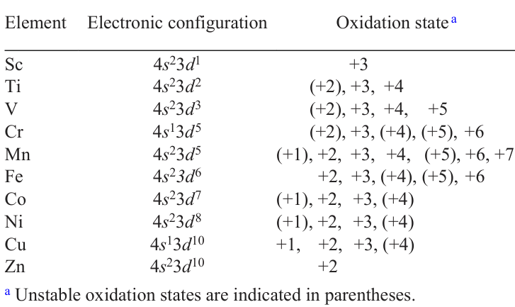
Nickel is an element of the tenth group of the fourth period in the Periodic System of Chemical Elements, has atomic number 28 and relative atomic mass 58.693, and is a member of the 3d-metal group. A distinctive feature of the electronic structure of 3d-metals, which includes chemical elements from scandium to zinc (4s23d1 – 4s23d10), is the presence of valence electrons on the 4s- and 3d-orbitals (Table 1). They determine the chemical properties of these elements and their compounds. 4s-electrons first participate in the formation of chemical bonds of covalent or ionic type, and 3d-electrons are only then involved in the process. ‘Rich chemistry’ of 3d-elements is due to the possibility of realizing a wide range of oxidation states — from low, represented mainly by cations or neutrally charged complexes (Mn2+, Ni(CO)4), to high, existing in anionic forms (Cr2O72 –, MnO42 – ). The greatest diversity of oxidation states is specific for metals of the middle 3d-row (see Table 1). The wide range of realized oxidation states explains the attractive properties of many solid-state compounds of 3d-metals and, undoubtedly, their electrochemical activity, which makes such compounds important components for MIBs.
3.2. Peculiarities of the electronic structure of 3d-metal cations within the crystal field theory
In the structures of MIB cathode materials, the 3d-elements have a 6-fold coordination, which is characterized by octahedral geometry. The crystal field theory (CFT) serves as a simplified but illustrative way of describing the electronic structure of octahedral MO6 complexes. According to this theory,12, 13 five fold degenerate d-orbitals of the transition metal ion when interacting with the electrostatic field of ligands of octahedral symmetry Oh split into three lower energy t2g-orbitals and two higher energy eg-orbitals, which are separated from each other by the energy Do (removal of degeneracy also occurs in the case of placing the transition metal ion in a tetrahedral environment (Td), but in a different way) (Fig. 6a). The difference in energy between the t2g and eg orbitals is due to the fact that the eg orbitals have lobes pointing toward the negatively charged ligands located in the vertices of the octahedral complex, which causes an increase in Coulomb repulsion. At the same time, the t2g orbitals have lobes pointing between the ligands (Fig. 6b). According to Hund’s rule, the first three d-electrons occupy separate t2g orbitals, forming a configuration with parallel spins (d 2 and d 3 configurations in Fig. 6c). The energy level of t2g-orbitals in an octahedral environment is 0.4 Do lower than the energy level of the degenerate d-orbitals in a spherical electrostatic field with a negative charge equivalent to the total charge of the ligands (dashed line in Fig. 6a). This leads to the stabilization of such a configuration; the ligand-field stabilization energy is 0.4 Don, where n is the number of electrons on the t2g-orbitals.
![[{"id":"QDTPGR0XWR","type":"paragraph","data":{"text":"(<i>a</i>) Configuration of 3d-orbitals of transition metals in tetrahedral (MO<sub>4</sub>) and octahedral (MO<sub>6</sub>) complexes, respective to the spherical field of negative charge; (<i>b</i>) orientation of e<sub>g</sub>- and t<sub>2g</sub>-orbitals related to ligands in the octahedral complex; (<sub>c</sub>) d-orbital occupation order in the octahedral 3d<sup>n</sup>-complex. Figures <i>a</i> and <i>c</i> were created by the authors of the review on the basis of the data of Ref. 15, Fig. <i>b</i> — on the basis of the data of Ref. 14."}}]](/storage/images/resized/MwiJJlpbDzLZ3ATzrJ2pZY3iHcLFmqD4Q5VhzXED_xl.webp)
An extra electron (3d 4) added to the system with the 3d3 configuration can occupy either one of the occupied t2g-orbitals with opposite spin or one of the free eg-orbitals (Fig. 6c). In the first case, a strong Coulombic repulsion is experienced between the paired electrons (pairing energy P), which should be overcome. In the second case, additional energy Do is consumed to occupy a higher energy eg-orbital. The high-spin (HS) configuration with occupying one of eg-orbital (t2g3eg1) is more favorable at Do < P, while at Do > P the low-spin (LS) configuration with the formation of paired electrons (t2g4eg0) is more favorable. While the ground state electronic configurations of octahedral complexes for 3d 1 – 3d 3-ions (Ti3+, V3+ and Cr3+) and for 3d 8 – 3d 10-ions (Ni2+, Cu2+ and Zn2+) are unambiguous — t12g, t22g, t32g and t62geg2, t62ge3g, t62ge4g, respectively (Fig. 7), then for a number of complexes of 3d4 — 3d7 ions (Mn3+, Fe3+, Co3+ and Ni3+) the strong field (Do > P) leads to the formation of LS-configuration with predominantly occupied t2g-orbitals, and the weak field (Do < P) leads to the occupying of eg-orbitals with the formation of HS-configuration. The electronic configuration of the ion in the octahedral complex affects its ionic radius (Fig. 7), which decreases both with the increase in the number of electrons on the d-orbitals and with the transition from HS- to LS-configuration (by ~ 10%).
![[{"id":"anB0MESPBl","type":"paragraph","data":{"text":"The d-orbital occupation scheme for M<sup>3+</sup> cations in an octahedral complex. Octahedral field stabilization energies (in Δ<sub>o</sub> units; top row of numbers) and ionic radii (R in Å, bottom row of numbers; for comparison, R<sub>Li</sub> = 0.76 Å) are provided for each configuration. The figure was created by the authors of the review on the basis of data from Refs 15, 16."}}]](/storage/images/resized/SSmv21cj9ZePtcxWZegurg2M6LVUHARheJe2wNup_xl.webp)
As noted above, d-metals can demonstrate different oxidation states that are relatively stable in octahedral complexes. For example, the states with empty, half or fully occupied eg or t2g orbitals (or both types at once) can be considered as stable. Thus, the 3+ oxidation state in terms of 3d-orbital occupancy is specific for scandium, chromium, high-spin both iron and copper, low-spin cobalt. Nickel in an octahedral complex is most stable in the 2+ oxidation state: in this case, an electronic configuration with fully occupied t2g-orbitals and half-occupied eg-orbitals with parallel spins (t62ge2g) is formed; a configuration with no electrons in the eg-orbitals (low-spin Ni4+ ion, t62ge0g) can also be considered relatively stable (Fig. 8).
![[{"id":"b7QDcnBAJy","type":"paragraph","data":{"text":"Schematic representation of the 3d-orbitals of 2+ – 4+ nickel in an octahedral complex. For Ni<sup>3+</sup> and Ni<sup>4+</sup> only LS-configurations typical for O<sup>2 –</sup> ligands are shown. The figure was created by the authors of the review on the basis of the data of the Ref. 15."}}]](/storage/images/resized/As62TxzRJ8BAU6S7cmeckzcDrYjjYCzsGulwg7f7_xl.webp)
The crystal field theory primarily considers the electronic structure of transition metal compounds from the point of view of the electrostatic metal-ligand interaction. This approach is highly simplified because it does not take into account the significant role of covalent interaction.17 Thus, the theory is unsuitable for describing the electrochemical processes associated with the exchange of electrons between the cationic and anionic sublattices in electrode materials. However, it can provide clear qualitative explanations for a number of regularities in the cathode materials of MIB, such as changes in the electronic structure and redox potentials of M(n + 1)+/Mn+ pairs in the raw of transition metals, the tendency of transition metal cations to migrate between the crystallographic positions, etc.18 – 21 To take into account the effect of covalent binding on the electronic structure of electrode materials, the crystal field theory is supplemented with the concepts of interaction between the p-orbitals of the ligand and the d-orbitals of the transition metal.
3.3. Main features of the electronic structure of nickel-containing cathode materials
The covalent character of the metal – ligand chemical bond is determined by the proximity in energy of the 3d-orbitals of the transition metal and the np-orbitals of the ligands and their significant overlapping with the formation of σ- and π-bonds. In the octahedral ML6 complex the 4s-, 4p-orbitals and two of the five 3d-orbitals (eg) of transition metal are capable of σ-overlapping with the p-orbitals of the ligand L forming lower σ-bonding and upper σ*-antibonding molecular orbitals (Fig. 9). Three remaining 3d-orbitals (t2g) participate only in a much weaker π-interaction also with the formation of π-bonding and π*-antibonding orbitals. The part of the molecular orbital diagram of the octahedral complex containing the antibonding t*2g and e*g orbitals corresponds to the orbitals considered in the crystal field theory. If the complex is placed in a periodic electrostatic field of the crystal, the bonding orbitals form a wide (M – L) band with a major L np-orbitals impact. Thus, the band is often considered as formed by the electronic states of the ligands. The (M – L)* band, on the contrary, is close-lying to M 3d-orbitals and is considered as formed by electronic d-states of the transition metal. It should be noted that, depending on the crystal structure and chemical composition, part of the p-orbitals of ligands may be incapable of bonding overlapping with d-orbitals, so a narrow non-bonding LNB band is formed near the upper edge of the (M – L) band.
![[{"id":"VtM2XVN8Pm","type":"paragraph","data":{"text":"Energy diagram of molecular orbitals formed by the interaction between the orbitals of the transition 3d-metal M and the octahedrally coordinated ligand L. The orbitals participating in σ(π) bonding and the bands formed from them are highlighted in pink (blue) color; non-bonding band of ligands is highlighted in green color; the bands that can be fully or partially occupied depending on the number of d-electrons are highlighted in color, the empty σ*(M – L)-bands are left without color. The figure was created by the authors of the review based on the data of the Ref. 15."}}]](/storage/images/resized/7SrSzCdBTZt9iFFI4wg2BdqSTy1SEb91Ua4eiuCW_xl.webp)
The participation in the redox reactions of the (M – L) and (M – L)* bands, consisting mainly of the p-orbitals of the ligand and the d-orbitals of the transition metal, respectively, is determined by their position relative to the Fermi level and depends on the energy difference between these bands. The difference is characterized by the charge transfer energy D, required to remove an electron from the occupied p-orbitals of the ligand and place it into the free d-orbitals of the transition metal (dn → dn + 1L, here L is a hole in the ligand orbitals).22 The D value decreases from left to right in the 3d-metal series with increasing oxidation state (Fig. 10). The D value also depends on the electronegativity of the ligand and the degree of M – L bond covalence: with the transition to a more electropositive ligand (e.g., from O2– to S2– or Se2–), the D value decreases and the energies of the (M – L) and (M – L)* bands decrease. This determines the competition between metal and ligand for the role of electron donor in the MIB cathode material.
![[{"id":"Wzeb1T7K0A","type":"paragraph","data":{"text":"Charge transfer energy Δ for the raw of 3d-metals in different oxidation states. The figure was created by the authors of the review based on the data of the Ref. 23."}}]](/storage/images/resized/pb751sPor0hoUOaIW2dcag3nif63WUkjHIXvLbq3_xl.webp)
The regularities of D change determine the reason why the end-row 3d-metals (including nickel) can be used only in MIB cathodes based on anions of highly electronegative elements, such as oxygen, and are not used with anions of more electropositive elements, such as sulfide or selenide ions. The electronic states of nickel (as well as cobalt and manganese) lie substantially below the upper edge of the S 3p-band (Fig. 11), which formally corresponds to a negative D value. Charging such a cathode material, it is the (M – S) band of the bonding S 3p-orbitals that will act as an electron donor, which leads to the weakening and breaking of the M – S bond. Only Ti4+/Ti3+ redox pair is characterized by a positive value of D may be suitable for chalcogenide cathode materials (see Fig. 11).
![[{"id":"SMDpp8bMd8","type":"paragraph","data":{"text":"Relative location of the M 3d and L np bands in sulfides and oxides. The energy difference between the upper edge of the L <i>np</i> band and the Fermi level in the anode material (metallic lithium Li<sup>+</sup>/Li or graphite) determines the operating voltage limit of the cathode at which the extraction of electrons does not affect the energy band of the bonding L np orbitals.<sup>10</sup>"}}]](/storage/images/resized/pX5GwePcPwov8uUegfG4J2p5tAIoYEhjOqv6qCz2_xl.webp)
The energetic proximity of the eg-states of nickel to the low-lying O 2p band determines the possibility of partial charge transfer from the ligand to the metal even for oxides. Thus, in accordance with the rules for determining the formal valence, nickel, having the electronic configuration d 7 (t 62ge1g), in many compounds has the 3+ oxidation state (LiNiO2, TRNiO3, TR — rare earth element). However, according to a number of studies, compounds with such a high formal oxidation state of nickel can transit to the insulator state with negative charge transfer (D < 0) with an electronic configuration d8L.24 In this state, part of the holes L spontaneously moves into the O 2p-band, which leads to the reduction of the electronic configuration of nickel to d8 (formally Ni2+).
3.4. Redox potentials of cathode materials based on transition 3d-metals
One of the main characteristics of the cathode material, directly affecting the specific energy of the battery, is the value of the operating potential, which is determined by the energy of (M – L)*-band corresponding to the redox pair M(n + 1)+/Mn+, relative to the Fermi level of the anode.19 In general, there is a correlation of the redox potentials of Mn+/Mn pairs in the reactions of binary compounds with lithium 25
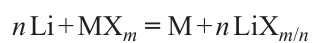
and average potentials of M(n + 1)+/Mn+ pairs in reversible lithium intercalation reactions with decreasing energy of d-orbitals26 and increasing electronegativity of M (Refs 27 – 29) when moving from left to right along the row of transition 3d-metals (Fig. 12). Nevertheless, a non-monotonic change of potentials of M4+/M3+ pairs (on the example of layered oxides LiMO2) and M3+/M2+ (on the example of mixed phosphates LiMPO4) is shown. This is connected with the peculiarities of the electronic structure, which can be qualitatively explained using the crystal field theory formalism (Fig. 13).
![[{"id":"1_uLKBR1aF","type":"paragraph","data":{"text":"Redox potentials of Mn<sup>+</sup>/Mn pairs in the reactions of binary compounds with lithium (n Li + MX<sub>m</sub> = M + n LiX<sub>m/n</sub>) and average potentials of M<sup>(n + 1)+</sup>/M<sup>n+</sup> pairs in the reactions of reversible intercalation of lithium cations (LiMO<sub>2</sub>, LiMPO<sub>4</sub>) for a series of transition 3d-metals. Allen electronegativity is a qualitative characterization of the change in the average energy of valence electrons. The figure was created by the authors of the review on the data of the Ref. 30."}}]](/storage/images/resized/QOnOio0nTEilSHK59kEP8d022IP7dWUZjrQ9bilF_xl.webp)
![[{"id":"-S63c0SF4R","type":"paragraph","data":{"text":"Energy levels of t<sub>2g</sub>- and e<sub>g</sub>-orbitals of transition metal M relative to the Fermi level in metallic lithium (E(Li<sup>+</sup>/Li)) for LiMPO<sub>4</sub> phosphates (<i>a</i>) and LiMO<sub>2</sub> oxides (<i>b</i>). P is the pairing energy, Δo is the orbital splitting energy in the octahedral complex. The position of orbitals along the energy axis is given to illustrate trends and can not be used for quantitative comparison. The scheme does not take into account the possible removal of degeneracy due to the Jahn – Teller (JT) effect for the electronic configurations t<sub>2g</sub><sup>3</sup>e<sub>g</sub><sup>1</sup> and t<sub>2g</sub><sup>6</sup>e<sub>g</sub><sup>1</sup>. The figure was created by the authors of the review based on the data of Ref. 15."}}]](/storage/images/resized/2zFr5CFoJgIYUXOO9Gx08t9mL1bOjffIm0tsIrXw_xl.webp)
The doubly charged cations of manganese, iron, cobalt, and nickel in an octahedral coordination of oxygen anions are in the high-spin state (P > Do), with the Mn2+ cation (d5) having a symmetric electronic configuration t32ge2g, in which the eg level serves as an electron donor (Fig. 13a). To add one more electron to the t2g level during the transition from Mn2+ to Fe2+ (d6, t42ge2g), the pairing energy P must be spent to overcome Coulomb repulsion. It raises the energy of this electron above the eg-level in Mn2+ and leads to the following ratio of electron potentials:

which is observed in LiMPO4 phosphates (see Fig. 12). The same destabilizing contribution of the pairing energy is specific for Co2+ and Ni2+ cations. Accordingly, the Mn3+/Mn2+ redox pair has an anomalously high potential compared to the systematic change of potential in the series of oxides LiFePO4 – LiCoPO4 – LiNiPO4.
By increasing the M2+ charge by one, the value of Do, which leads to the formation of high-spin states of Mn3+ and Fe3+ and low-spin states of Co3+ and Ni3+ cations, increases for the three-charged M3+ cations (Fig. 13b). Thus, while in the case of Mn3+ and Fe3+ cations the electron donors are eg-orbitals, for the low-spin Co3+ cation (t62ge0g) the valence electrons are located on the lower t2g orbitals. The addition of one more electron to Co3+ (t62ge0g) leads to partial occupation of the higher eg-orbitals. Thus, the electrode potential E(Co4+/Co3+) becomes the highest in the series of compounds LiMnO2 – LiFeO2 – LiCoO2 – LiNiO2. It should be noted that the absence of electrons on the σ-antibonding eg-orbitals of the low-spin Co3+ cation is also manifested in the shortest metal-oxygen distances (d) in the MO6 octahedra of the LiMO2 structure (d(Mn – O) =2.106 Å, d(Fe – O) = 2.061 Å, d(Co – O) = 1.917 Å, d(Ni – O) = 1.976 Å).
The significant difference in the electrode potentials of the Ni3+/Ni2+ redox pair for LiNi1/3Mn1/3Co1/3O2 (~ 2.8 V vs. Li+/Li) and LiNiPO4 (> 5 V vs. Li+/Li) illustrates the important role of the ligand in the formation of the electrode potential. In both structures, nickel has an octahedral oxygen coordination. However, oxygen anions forma mixed covalent-ionic bond with another transition metal cation in the first case, and a strong covalent bonds with the P5+ cations within the phosphate group PO43 – in the second one. When the anion O2 – forms a covalent bond with another highly charged cation, the degree of ionicity of the Ni – O bond increases, leading to higher redox potential. Indeed, the position of the (M – L)* band relative to the 3d-orbital of the transition metal cation depends on the degree of covalency (ionicity) of the M – L bond and can be expressed as S2/Δc, where S is the integral of the overlapping of the M 3d and L np states, Δc is the difference between the electronegativities of the metal M and the ligand L (Fig. 14a).
![[{"id":"Oz2ZhXhBLK","type":"paragraph","data":{"text":"Dependences of the redox potential of the pair M<sup>(n + 1)+</sup>/M<sup>n+</sup>: (<i>a</i>) on the degree of covalent bonding for ligands L with relatively low (covalent polar bond M – L) and higher (ionic bond M – L) electronegativity, as well as for ligands combined into polyanionic groups XL<sub>n</sub><sup>m–</sup>;<sup>31</sup> (<i>b</i>) on the electronegativity of the cation X of the polyanionic group (χ(X') > χ(X));<sup>31</sup> (<i>c</i>) distribution of the redox potentials of M<sup>3+</sup>/M<sup>2+</sup> and M<sup>4+</sup>/M<sup>3+</sup> pairs <i>vs.</i> Li<sup>+</sup>/Li, calculated using density functional theory with Hubbard correction (DFT + U), in transition metal phosphates (●) and average redox potentials calculated for the triple oxides using the database of crystal structures of inorganic compounds (▲); dashed line indicates the ultimate working potential of a commercially available electrolyte based on LiPF<sub>6</sub> solution in alkyl carbonate mixture; (<i>d</i>) influence of the inductive effect on the potential of Ni<sup>3+</sup>/Ni<sup>2+</sup> redox pair in LIB cathode materials; it should be noted that the given values of potentials are not the resulting potential in mixed compounds (so, in layered oxides LiNi<sub>x</sub>Mn<sub>y</sub>Co<sub>z</sub>O<sub>2</sub> (NMC) at deintercalation of lithium oxidation is realized sequentially: Ni<sup>3+</sup>/Ni<sup>2+</sup> (2.8 – 3.2 V), Ni<sup>4+</sup>/Ni<sup>3+</sup> (3.2 – 3.5 V) and Co<sup>4+</sup>/Co<sup>3+</sup> (> 3.5 V), the resulting potential of the compounds is 3.6 – 3.7 V); the stability range of commercially available electrolytes (2.0 – 4.5 V) for lithium-ion electrochemical systems is highlighted in gray. Figures <i>c</i> and <i>d</i> were created by the reviewers based on data from the Refs 34 – 40."}}]](/storage/images/resized/wq8l4y6gtdYryRvfGyMSqQEldG9mT1d8Nd09ay60_xl.webp)
At a higher value of Δc, corresponding to a more ionic M – L bond, the value of S2/Δc decreases, and hence the energy of the (M – L)* states decreases and the electrode potential increases.31 If the ligand L simultaneously forms a covalent bond with another cation X, then the states that mix with the d-orbitals of the transition metal are the bonding states X – L, which are lower than the L np orbitals (Fig. 14a).31, 32 This leads to an increase the M – L bond ionicity, and decrease in the antibonding orbitals (M – L)* level relative to E(Li+/Li) with a corresponding increase a corresponding increase in the electrode potential. In this case, the electrode potential increases along with the increase in the electronegativity of the cation X (Fig. 14b). This ‘inductive’ effect may have the greatest influence on the position of the M(n + 1)+/Mn+ redox pair.31, 33 For example, the potential of the M(n + 1)+/Mn+ pair in phosphorus-containing polyanionic* compounds shifts to a region of higher values compared to their oxide analogues34 (Fig. 14c).
Depending on the type of ligand, the potential of the Ni3+/Ni2+ redox pair can vary from ~ 3 in layered oxides to 5.4 V vs. Li+/Li in the Li2NiP2O7 compound (Fig. 14d). A similar situation is observed for sodium compounds: depending on the type of polyanionic ligand, the Ni3+/Ni2+ pair potential can have a value of > 5 V vs. Na+/Na (Ni3+/Ni2+ pair potentials are ~ 3, 4.4, 4.8, and > 5 V, respectively, for NaNi0.5M0.5O2, NaNiPO4, Na4Ni3(PO4)2(P2O7) and Na4NiP2O7F2).41 – 43 Too high an operating potential is a major problem for nickel-containing polyanionic compounds, as it goes beyond the electrochemical stability window of the currently used electrolyte solvents. This severely limits the experimental study of the electrochemical characteristics of nickel-containing polyanionic compounds,38, 44 and a systematic analysis of the inductive effect in these materials seems to be possible mainly only by computer modeling methods. Thus, nickel-containing cathode materials that can be used in real MIBs are not characterized by a variety of available structural types, unlike, for example, iron-, manganese-, or vanadium-based compounds.45 – 47 Perhaps, the problem of the high electrode potential of nickel-containing polyanionic cathodes will be solved by the transition to batteries with solid electrolytes or by the development of high-voltage liquid electrolytes. At present, the main nickel-based cathode materials are layered oxides LiMO2 (M = Ni, Mn, Co, Al).
* In this context, polyanionic refers to compounds containing polyatomic anions such as PO43–, SO42–, SiO44–, CO32–, BO33–, and others.
4. Cathode materials based on nickel-containing layered oxides for metal-ion batteries
4.1. Crystal structure of nickel-containing layered oxides
The crystal structure of layered oxides with the general formula AxMO2 (A — alkali metal) is formed by alternating layers (MO2), which consist of MO6 octahedra connected by edges. Alkali metal cations are located between the layers. Oxygen anions forming the octahedral layers can arrange themselves according to either the close-packing of equal spheres (CPS) or sphere packing (SP) motif. For A = Li, the predominant motif is the three-layer cubic closest packing of oxygen anions (ABCABC),48 in which all octahedral voids are layer-by-layer occupied by transition metal cations M and lithium cations (Fig. 15a); it can be considered as a layered superstructure compared to the structural type of rock salt (LiMO2 ≡ (Li0.5M0.5)O). The space group R3–m and hexagonal unit cell with parameters a ≈ aRS /2 ≈ 2.9 Å, c ≈ aRS23 ≈ 14.2 Å (aRS is the parameter of the cubic subcell of rock-salt type structure) correspond to the most symmetric variant of such structure. A distinctive feature of the closest packing is the possibility of shifting the oxygen layers relative to each other, which leads to the transformation of part of the cubic CPS layers into layers with the two-layer hexagonal closest packing of ABAB, and the octahedral coordination of alkali and transition metal cations does not change at such a shift, but the bonding of octahedrons AO6 and MO6 through common edges changes to the bonding through common faces (Fig. 15b). The arrangement of the two oxygen layers is also possible according to the ball-on-ball motif of SP (as opposed to ball-in-hole in CPS), which corresponds to two identical neighboring letters in the layer sequence, e.g ... ABBA; this arrangement is never realized in the CPS. Alkali metal cations located between identical oxygen layers acquire trigonal-prismatic coordination (Fig. 15c).
![[{"id":"SHnYUCAkqV","type":"paragraph","data":{"text":"Representation of coordination polyhedra MO<sub>6</sub> and AO<sub>6</sub> in A<sub>x</sub>MO<sub>2</sub> layered oxide structures with cubic (<i>a</i>) and hexagonal (<i>b</i>) CPS, as well as with SP motif (<i>c</i>); projections of crystal structures of O3 (<i>d</i>), O1 (<i>e</i>), and P2 ( <i>f</i> ). The size of the highlighted sector of the sphere of cation A corresponds to the occupancy of this position. The figure was created by the authors of the review based on the data from the Cambridge Structural Data base, as well as the Refs 49 – 51."}}]](/storage/images/resized/onl3Dw9gLLZHP5Nf9cyGl4VW3yrGomHZ3aAWX8kB_xl.webp)
At present, the system of designation of structures of layered oxides proposed in Ref. 52 is generally accepted. This system assigns to each structure a two-character designation consisting of the Latin letter O or P depending on the coordination of the alkali metal (O — octahedral, P — trigonal-prismatic) and the number indicating of layers (MO2) per repeating period along the axis perpendicular to these layers. The structures based on cubic and hexagonal CPS are represented in such designations as O3 (ABCABC, Fig. 15d ) and O1 (ABAB, Fig. 15e), and the structures with SP blocks are represented as P2 (ABBA, Fig. 15f) and P3 (ABBCCA). ‘Competition’ between O and P structures depends on the chemical composition, size factor and the nature of the metal – oxygen bond. Thus, trigonal-prismatic coordination is realized for large A-cations (Na+, K+) at their significant deficiency (x < ~ 0.75 in the AxMO2 formula) and at a high degree of covalence of the metal-oxygen framework.52 A semi-quantitative description of the stability of the O and P structures was proposed using the ionic potential (the ratio of the formal charge of the ion n to its ionic radius R), which determines the polarization ability of the ion. The cationic potential was introduced as a descriptor
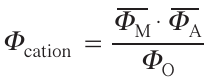
Here Φ̅M is the average ionic potential of the transition metal cation
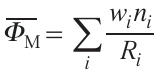
wi is the fraction of transition metal Mi with charge ni and ionic radius Ri ,
where x is the content of cation A in the formula AxMO2 , RA is the ionic radius of cation A, Φ̅O is the ionic potential of oxygen.53
The stability regions of O3 and P2 structures are separated on the Φcation – Φ̅A map by the straight line Φ̅A = 0.4 Φcation + 1.6 (Fig. 16). A higher cationic potential ‘implies’ a greater covalency of the M – O bond and the spatial extent of the valence orbitals of the transition metal, and, consequently, a stronger electrostatic repulsion between the layers (MO2). The latter favors the formation of the P2 structure with an increased interlayer distance dO – A – O. At the same time, as the alkali metal content (x) increases the shielding between adjacent layers (MO2) increases and the O3 structure with a smaller dO – A – O distance is stabilized.
![[{"id":"dXuEuyMgis","type":"paragraph","data":{"text":"Stability map of O3 and P2 crystal structures of layered oxides AxMO2 in Φ<sub>cation</sub> – <i>Φ̅ </i><sub>A</sub> coordinates. The figure was created by the authors of the review based on the data from the Ref. 53."}}]](/storage/images/resized/pn3jrzFM1Ng3A7JLWNoWUkR6YdF4XrhspmQg7MYM_xl.webp)
4.2. The Jahn – Teller effect in structures of nickel-containing layered oxides
Low-spin octahedral complexes of nickel with oxidation state +3 with one electron at the eg-orbital (t62ge1g) could be additionally stabilized due to the JT effect. That effect implies the decrease of the total energy of the electronic system at removal of the energy degeneracy between two eg-orbitals due to distortion of the octahedral coordination environment and lowering of its symmetry. This phenomenon is also observed in materials in which octahedral complexes with high-spin cations Mn3+, Fe4+ and low-spin Co2+ are present. However, the Jahn – Teller theorem does not formulate a specific type of distortion of an octahedral complex, which could be resulted in, for example, an elongation of Ni – L bonds along one of the octahedral axes, as schematically shown in Fig. 17.
![[{"id":"zVgmPBPAOm","type":"paragraph","data":{"text":"Schemes of energy splitting of e<sub>g</sub>-orbitals of low-spin Ni<sup>3+</sup> cation and axial JT-distortion of NiL<sub>6</sub> octahedron. The figure was created by the authors of the review based on the data of the Ref. 14."}}]](/storage/images/resized/sFeccdSpx44mGiPArQypBq2srYJMAqPuMQTsTAmp_xl.webp)
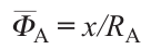
In crystalline solids, JT-distorted octahedra are most often connected by common vertices (e.g., in the structure of perovskite AMO3 or in the Ruddlesden – Popper phase structures An + 1MnO3n + 1) or common edges (e.g., in the structure of layered oxides such as α-NaFeO2), so they cannot be distorted independently of each other. However, even in the absence of direct contact between JT-active octahedrons, distortions in neighboring octahedrons will create additional stresses, which can then propagate in the structure, resulting in the cooperative JT effect under the action of electron-vibrational interactions.54 Relaxation of the structure due to the removal of degeneracy of eg-orbitals can occur under the action of one of the two JT-active octahedral modes of electron-vibrational interaction (Q2 or Q3 , Fig. 18) with the formation of sets of Ni – O bond lengths. Three pairs of different bond lengths (l1,2,3 × 2) can be identified for nickelates with perovskite structure, and four short and two long bonds (l1 × 4 and l2 × 2, where l1 < l2) — for layered and spinel structure nickelates (Table 2).
![[{"id":"XEKyhHr3rF","type":"paragraph","data":{"text":"JT-Active octahedral electron-vibrational modes Q<sub>2</sub> and Q<sub>3</sub>. The figure was created by the authors of the review based on the data of Ref. 54."}}]](/storage/images/resized/q6cmEQHB0zBQiC4e9qGLxH5srT1lIn4bHp9E6xJB_xl.webp)
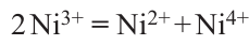
In the NaNiO2 (NNO) structure, the JT effect reveals itself as a cooperative distortion of NiO6 octahedra under the action of the Q3 mode with the elongation of two and shortening of four Ni – O bonds, which leads to a monoclinic distortion of the structure (R3–m → C2/m) and a ground state energy decrease by 79 meV per atom.64 NNO monoclinic structure remains the ground state up to the temperature of 460 K, then it transforms to a highly symmetric trigonal phase.65 The theoretical DFT + U study of LiNiO2 oxide (LNO), the structural analog of NNO, shows that the ground state with C2/m structure is more stable compared to the R3–m, similarly to NNO.54 The calculation results are in good agreement the XAFS results. The latter showed distortions of NiO6 octahedrons, in particular, a decrease of four Ni – O bonds (up to 1.91 Å) and an increase of two bonds (up to 2.09 Å), compared to the lengths of Ni – O bonds in an ideal NiO6 octahedron (1.97 Å).66 However, more recent works have found that the formation energy of the LNO structure with sp. gr. P21/c with JT octahedrons arranged in a zigzag order is lower than that of the sample structure with sp. gr. C2/m and collinear arrangement of distorted octahedrons.67 – 69 It has also been suggested that disproportionation might take place in LNO according to the following scheme 64
Because of the difference of ionic radii of Ni2+ and Ni4+ (0.69 and 0.48 Å, respectively, vs. 0.56 Å for Ni3+), the neighboring octahedrons should face stretching (compression), which might result in relaxation of the stresses in the structure with alternation of stretched (compressed) octahedrons, similar to perovskite-type nickelates (Fig. 19).70 Meantime, all considered distorted configurations of LNO have close formation energies and could appear as metastable states.64, 71 Indeed, a neutron diffraction study of LNO down to a temperature of 10 K revealed broadening of the reflections that could be assigned to monoclinic distortion (sp. gr. C2/m), however, all Ni – O distances in NiO6 octahedra are similar to each other and equal to 1.96 – 1.97 Å. That fact does not conform with the JT distortion scenario and could possibly be related to the multiplicity of local configurations.61 For example, Chung et al.61 examined the LNO structure using pair distribution function to establish and characterize local structure distortions. This approach revealed the presence of elongated NiO6 octahedra with average Ni – O lengths (see Table 2), which are in consistency with results obtained earlier from EXAFS studies.62 Thus, it is assumed that energetically degenerate JT-distorted configurations might be present in LNO in the form of nanometer-sized domains, that complicates their observation by diffraction methods.72
![[{"id":"9lXi7_khRQ","type":"paragraph","data":{"text":" Four candidates for the LNO ground state: the ideal undistorted R<i>3̅ </i>m structure (<i>a</i>); the C2/m structure with cooperative collinear JT distortion Q<sub>3</sub> (<i>b</i>); the P2<sub>1</sub>/c structure with cooperative zigzag JT distortion (c); the size-disproportionated P2/c structure obtained by the reaction (6) (<i>d</i>). The elongation and shortening of the Ni – O bonds are reflected in red and green, respectively. The figure was created by the authors of the review based on the data of the Ref. 71."}}]](/storage/images/resized/Yv4DI53lAlIIHd1QnYzjT8NZ9Z37UJO1Tvl5a5UL_xl.webp)
The variety of possible configurations of the LNO ground state could be explained by assuming that this oxide exhibits the behavior of a high-entropy glass,73 with both JT-distorted octahedra and uniformly stretched (compressed) NiO6 octahedra coexisting in its structure. The possible types of distortions that do not violate the connectivity of octahedra are illustrated in Fig. 20. The probability of formation of the glassy state agrees well with the fact that different distorted configurations, described above, have close formation energies, while the mixed states are even more energetically favorable due to the contribution of configuration entropy. Doping with other transition metals leads to further rise of entropy, resulting in higher the stability of LNO-based materials, that contributes to some extent to the successful application of layered NMC oxides as cathode materials for LIB.73
![[{"id":"RaMQU9-imT","type":"paragraph","data":{"text":"The possible types of ordering of short and long Ni – O bonds in the layers of NiO<sub>6</sub> octahedra in the LNO structure. Short and long Ni – O bonds are highlighted by red and green lines, respectively. Ordering of JT distorted octahedra with collinear (<i>a</i>) and zigzag (<i>b</i>) arrangement of long Ni – O bonds; in the following three size-dispersed structures, 50% (<i>c</i>), 67% (<i>d</i>), and 100% (<i>e</i>) of NiO<i><sub>6</sub></i> octahedra are isotropically compressed (six short bonds, which corresponds to the charge-localized Ni<sup>4+</sup> state) or elongated (six long bonds, which corresponds to the charge-localized Ni<sup>2+</sup> state). The values of total energy (in meV) per unit cell respective to the most stable configuration are given under each structure type. The figure was created by the authors of the review based on data in the Ref. 73."}}]](/storage/images/resized/T1KFirwiOP0q4FXzTIikfGA0rDKWzlYw4z1T1NmS_xl.webp)
An alternative explanation for the absence of JT distortions in LNO oxides was given by means of their electronic structure study via DFT using dynamical mean field theory (DFT – DMFT). Unlike DFT + U, the static mean-field approximation for the Coulomb interaction Hamiltonian is not used in the DFT – DMFT method.74 Although the ground state of LNO is presented by a ‘mixture’ of NiO6 octahedra with electronic configurations d7, d8L and d9L2 (~ 5%), in all configurations both eg-orbitals have the same electron population. Considering the system in dynamics, it was noted that even within the d7 configuration the electron density of the single electron is equally distributed between the two eg-orbitals, which in this case are equivalent, requiring no degeneracy. The dynamical nature of JT distortions in LNO is also confirmed by molecular dynamics calculations.71
Thus, the question of the presence of JT distortions of NiO6 octahedrons in LNO oxides so far remains open. Despite a general understanding of the absence of cooperative JT distortions was already achieved, up to now experts offer new explanations for this phenomenon, which is associated with the difficulties in the study of local distortions of the structure. Experimental methods fail to precisely study such atomic-level processes, and computer modeling methods, as it turned out, strongly depend on the approximations used.
4.3. Electronic and crystal structures of nickel-containing layered oxides during electrochemical cycling
4.3.1. Evolution of electronic structure
The deintercalation of alkali metal cations from cathode materials is accompanied by a decrease in the electron density at the (M – L)* antibonding orbitals. Since the main contribution to these orbitals is given by the transition 3d-metal states, the process can be considered as oxidation of Mn+ to M(n + 1)+, which is a cationic redox reaction. A necessary condition for such a process and the deintercalation of electrons exactly from the 3d-orbitals of the transition metal is the energy position of the (M – L)* band above the upper edge of the np-band of the anion (see Fig. 11).75 Otherwise, deintercalation of the alkali metal will be accompanied by the appearance of holes in the bonding (M – L) band, formed mainly by np-states of the ligand, which results in destabilization of the crystal structure of the cathode material.
In layered LiMO2 oxides (M = Ni, Mn, Co, Al), cobalt and nickel are transition metals changing the oxidation states during charging and discharging of the cathode material. It is interesting to compare the changes in the electronic structure of LCO and LNO upon lithium deintercalation. It is widely believed that the eg-orbitals of nickel in LNO oxide are higher in energy with respect to the upper edge of the O 2p-band than the t2g-orbitals of cobalt in LCO (Fig. 21a), so oxidation of Co3+ to Co4+ at > 50% lithium extraction results in partial removal of electrons from the bonding (M – O) band, which reduces the stability of highly delithiated lithium cobaltite towards decomposition with oxygen release.76 In contrast, oxidation of Ni3+ to Ni4+ with extraction of electron density from the antibonding eg orbitals, which are energetically located above the upper edge of the (M – O) band (Fig. 21b), enables the deintercalation of much more lithium from the LNO structure, compared to LCO, in the same potential range (2.7 – 4.3 V vs. Li+/Li). Due to this, LNO-based cathode materials possess a high specific capacity close to the theoretical one.77 However, the analysis of the electron state density distribution obtained by (DFT + U)-modeling (Fig. 21c) suggests that the d-orbitals of the metal and p-orbitals of the ligand are strongly hybridized, i.e., they cannot be divided into states belonging only to the metal or to the anion (metal or oxygen). Even in stoichiometric LCO, for the group of vacant eg-orbitals above the Fermi level and occupied t2g-orbitals, on which the d-states of cobalt prevail, hybridization with 2p-states of oxygen also takes place. Deintercalation of lithium is accompanied by a decrease in the electron density at the hybridized t2g-orbitals, which leads to oxidation of not only cobalt, but also partially oxygen. This is evident even for Li0.9CoO2; at lithium deintercalation up to Li0.5CoO2 the electron density derives mainly from cobalt and only partially from oxygen states, but the contributions of 3d-orbitals of cobalt and 2p-orbitals of oxygen to the density of states near the Fermi level are nearly equal. Up to this limit, there is no significant destabilization of the structure due to partial oxygen oxidation, and the LCO has stable electrochemical cycling.6 Upon further deintercalation of lithium, the bonding (M – O) band act as electron donors; this eventually leads to oxygen release and collapse of the layered structure.78
![[{"id":"h59F29Xy49","type":"paragraph","data":{"text":"Schematic representation of the energy levels of 4+/3+ redox pairs in LCO (<i>a</i>) and LNO (<i>c</i>); the electron density, extracted from the orbital by deintercalation of 0.5 Li, is highlighted in yellow. Total density of electronic states (highlighted in white) and partial densities of electronic states on cobalt, nickel (highlighted in blue), and oxygen (highlighted in red) in Li<sub>x</sub>CoO<sub>2</sub> (<i>b</i>) and Li<sub>x</sub>NiO<sub>2</sub> (<i>d</i>) as a function of <i>x</i>. DOS is the density of electronic states; the Fermi level (E<sub>F</sub>) is chosen as 0 on the energy scale. The Hubbard correction (<i>U</i>) was 3.4 and 6.2 V for cobalt and nickel, respectively. The figure was created by the authors of the review based on the data of the Ref. 69."}}]](/storage/images/resized/fzQsgVHfSrZmjSgvlGml57dOioibiWqh6gHlEuDh_xl.webp)
Unlike LCO, LNO is not characterized by a pronounced dominance of the contribution of 3d-states of nickel near the Fermi level (Fig. 21d ), which corresponds to a more covalent Ni – O bond. Due to the presence of an additional electron in Ni3+ (see Fig. 8), the conduction band is formed by eg-states with a significant contribution of 2p-orbitals of oxygen. Under deintercalation up to the composition ~ Li0.3NiO2, oxidation proceeds by extraction of electron density from the antibonding eg-orbitals, which does not weaken the Ni – O bond and does not lead to destabilization of the crystal structure.79, 80 Upon further deintercalation of lithium, as noted above, charge transfer from oxygen to nickel occurs, the interlayer distance in the LNO structure is reduced, and partially oxidized oxygen forms are formed.81
Particular attention should be paid to compounds in whose structure a part of the O 2p-orbitals does not have a strong σ-overlap with the TM d-orbitals. Such compounds include lithium-rich oxides Li1 + xM1 – xO2 with a layered structure or with the structure of disordered rock salt. Due to the substitution of a part of transition metal cations by lithium, for a part of oxygen atoms an OLi4M2 crystal field with linear structural fragments Li – O – Li is realized instead of the octahedral crystal field with three Li cations and three transition metal cations (OLi3M3).82 – 85 p-Orbitals of oxygen oriented along these fragments become incapable of forming σ-bonds with transition metal cations. These orbitals can serve as an additional ‘reservoir’ of electrons that can be used for charge compensation during extraction of additional lithium without the risk of the cathode material crystal structure collapse.
Compounds showing redox activity of both cationic and anionic sublattice upon (de)intercalation of alkali metals are considered as promising cathode materials for high energy density LIBs.86 Among lithium-rich complex oxides, the most studied are solid solutions Li4/3 – xNix2+Mn4+2/3 – xCox3+O2 (x = from 0 to 1/3), in which nickel makes a significant contribution to the redox activity of the cationic sublattice due to the sequential realization of redox pairs Ni3+/Ni2+ and Ni4+/Ni3+ (see Refs 87, 88). The peculiarity of such compounds is that the participation of the anionic sublattice in charge compensation is accompanied by negative factors such as a progressive voltage fade (and, consequently, of the stored energy) and a significant voltage hysteresis on the charge and discharge, as high as, for example, ~ 0.4 V for the composition Li1.2Ni0.13Mn0.54Co0.13O2 .89 One of the possible origins of voltage hysteresis is kinetic limitations caused by electron transfer between the anion and cation sublattices, which results in the formation of metastable highly oxidized cationic states.90 For nickel, such a long-lived metastable state is Ni4+, whose appearance upon charging and disappearance upon relaxation due to charge transfer from the ligand to the metal has been demonstrated in a model system based on Li1.17Ti0.58Ni0.25O2 with a disordered rock salt structure.91 According to the Marcus theory,92 the direct removal of electrons from non-bonding 2p oxygen states is a non-adiabatic process, while the removal of electrons from delocalized Ni 3d – O 2p σ-type states, in contrast, is an adiabatic process (Fig. 22). At the same time, charge transfer via a nonadiabatic mechanism can proceed several orders of magnitude slower compared to the adiabatic one (a difference of five orders of magnitude was obtained for TiO2 (Ref. 93)), which makes the transition to an intermediate metastable state possible. According to this scheme, the oxidation of O2– anions does not proceed directly to O2n – or O2; at the initial stage, an intermediate kinetically stabilized state Ni4+/3+ is formed, the appearance of which triggers local structural distortions due to the JT effect and an increase in Ni – O orbital hybridization, which facilitates the internal charge transfer from O 2p to Ni4+/3+ (Ref. 91). The slowed charge transfer process from oxygen anions to nickel cations (and vice versa) in turn leads to the appearance of operating voltage hysteresis (potential difference during charging and subsequent discharge), which reduces the energy efficiency of the battery.94
![[{"id":"-gQn8Rge8f","type":"paragraph","data":{"text":"Schematic representation of the transition from the Ni<sup>3+</sup> + O<sup>2–</sup> state to the Ni<sup>3+</sup> + O <sup>–</sup> + e<sup>–</sup> state <i>via</i> the Ni<sup>4+</sup> + O<sup>2–</sup> + e<sup>–</sup> in termediate state. The figure was created by the authors of the review based on the data from the Refs. 90, 91."}}]](/storage/images/resized/ohw2OpI2Zuu2dulY5d92S4tF7A3R9pdrvhASzPpf_xl.webp)
Note also that the so-called reductive coupling effect is observed for nickel cations. For example, after extraction of 0.5 Li from Li1.3Ni0.27Ta0.43O2, oxidized On– ions coexist with Ni3+ and Ni4+, which indicates the overlap of non-bonding O 2p-orbitals with eg-orbitals of nickel. Thus, nickel is not able to reach the maximum oxidation state, because at a certain point it is more energetically favorable to oxidize the non-bonding oxygen orbitals.84, 95
4.3.2. Phase transitions in layered oxides ANiO2 (A = Li, Na)
Changes in the values of Φcation and Φ̅A in layered oxides when changing the oxidation state of the transition metal as well as the A-cation content during electrochemical cycling can result in phase transitions between different types of layered structures. Additional complication of the crystallochemistry of A-deficient layered oxides may arise from the ordering of A-cations and cation vacancies, charge ordering, the JT effect, and cation migration. The gradual structural transformations, appeared upon alkali metal (de)intercalation process, determine to a great extent the electrochemical behavior of cathode materials and the MIB working characteristics.
During the electrochemical cycling in the potential range from 2.7 to 4.8 V vs. Li+/Li the LNO structure undergoes a series of phase transitions from hexagonal H1 (the initial O3 structure with sp. gr. R3̅ m, belonging to trigonal, not to hexagonal crystal system) through monoclinic phase (M) to hexagonal phases H2 → H3 → H4 (Fig. 23) with substantially different ratios of c/a lattice parameters and different unit cell volumes.96 – 99
![[{"id":"KyBj0oK1QK","type":"paragraph","data":{"text":"Galvanostatic charge (discharge) curves of the first cycle at different values of the charge potential (<i>a</i>) and differential capacity curve d<i>Q</i>/d<i>V</i> (plot of the first derivative of the charge <i>Q</i> at potential <i>V</i>) of the first cycle (<i>b</i>).<sup>77</sup>"}}]](/storage/images/resized/C0ly85HxHJRgUnSt7BS2GGyi0F2EVFHYtRgae6jL_xl.webp)
The phase transition from hexagonal H1 to monoclinic structure M (sp. gr. C2/m: a ≈ 4.99, b ≈ 2.83 and c ≈ 5.07 Å; b = 109.7°) proceeds at potentials ~ 3.5 – 3.6 V vs. Li+/Li, i.e., after extraction of ~ 0.25 Li.96, 99 – 102 In M phase the layers stacking remains typical for the O3 structure (such distorted phases are often designated with the addition of a dash: O'3). The monoclinic distortion is caused by the ordering of lithium cations and cation vacancies formed during charging and can be local, i.e., present in the domain form.103, 104 Theoretical calculations show that the ordering of occupied and vacant lithium positions is attributed to the presence of short-range electrostatic repulsive forces between Li+ cations inside one layer and long-range electrostatic attractive forces between such cations in the neighboring layers Lix, transmitted through the layers (NiO2) though JT-distorted NiO6 octahedra. Infinite chains – LiA – O – Ni3+ – O – LiB – , where LiA and LiB are atoms in neighboring layers, occur in the monoclinic structure. The presence of the Li – O bond leads to a decrease in the energy of the partially filled eg-orbital of Ni3+ oriented along the O – Ni3+ – O bond in the chain via a mechanism similar to the inductive effect (see Fig. 14); this stabilizes such linear configuration.105 Calculations have also shown that the stability range of the monoclinic distortion is limited to the composition with x(Li) = 0.4.102
Phases H2, H3 are based on the O3-type structure and contain stacking faults, which are hexagonal layers of the O1 structure with extracted lithium cations.106 – 108 In contrast, the H4 phase formed at highly delithiated states has the O1 structure (pr. gr. P3̅ m1), in which stacking faults are presented by layers with the cubic O3 structure with remaining lithium cations (Fig. 24). The formation of the H4 phase is observed at higher potentials (> 4.7 V vs. Li+/Li)108, 109 and/or at prolonged holding at a potential of ≥4.2 V vs. Li+/Li due to the sluggish kinetics of phase transition H3 → H4.108 The stabilization of the O1 structure at decreasing lithium content is explained by electrostatic repulsion of the domains of 2p-orbitals of oxygen: in the O3 structure, the ‘lobes’ of the 2p-orbitals of oxygen atoms in neighboring layers are pointed at each other and the center of the octahedral void, the repulsion between the ‘lobes’ is compensated by the attraction of the Li+ cation located in this void; at lithium deintercalation it becomes more favorable to shear the layers with transformation into O1 structure, in which the orbitals are directed towards the centers of neighboring tetrahedral voids and not to each other, as in O3 structure.106
![[{"id":"bPuRTLUrLK","type":"paragraph","data":{"text":"Sequential transition of the <i>H</i>1 phase to the <i>H</i>4 phase via the <i>O</i>3 structure with <i>O</i>1-type stacking faults and the <i>O</i>1 structure with <i>O</i>3-type stacking faults. The atom designations are similar to those in Fig. 15. The figure was created by the authors of the review based on the data of the Refs 106 – 108."}}]](/storage/images/resized/10q0KfTCik9YdOpnC5nHMTSURcyZnelx43kd111u_xl.webp)
The distance between the oxygen anion layers located above and below the lithium cation layer increases almost monotonically with the decrease of Li content up to x(Li) = 0.3, which corresponds to the increase of electrostatic repulsion between the anion layers due to the weakening of screening by the positive charge of the lithium cation layer.106 However, further the phase transition H2 → H3 at x(Li) < 0.26 is accompanied by a drop of the distance between the oxygen layers and its sharp decrease at x(Li) < 0.14 upon delithiation of the H3 phase, leading to a rapid decrease in the unit cell parameter from ~ 14.4 to ~13.4 – 13.6 Å and its volume by ~ 3.8%.99, 101 This structural collapse is related to changes in the electronic structure of LixNiO2: a decrease in the D energy, an increase in the hybridization of O 2p- and Ni 3d-states and the formation of holes in the O 2p-band with partial charge transfer to the eg-orbitals of nickel. This results in a decline of electron density on oxygen atoms, a decrease in electrostatic repulsion, and a reduction of the interlayer distance.110
NNO layered oxide, which also crystallizes in the O3 structure, differs from LNO by the presence of cooperative JT distortion of NiO6 octahedrons. Due to the large radii of the Na+ ion, the distance between the layers (NiO2) is ~ 5.6 Å, which is much larger than one ~ 4.8 Å for LNO. During the charging process in the potential range of 2.5 – 4.0 V vs. Na+/Na, NNO oxide undergoes at least four phase transformations, appeared at the galvanostatic curve as a plateau at ~ 2.6 (1), 3.05 (2), 3.4 (3), and 3.5 V (4) (Fig. 25).111, 112 Although the observed phase transitions are reversible, it is impossible to get a stoichiometric composition with x = 1 at the discharge process.112
![[{"id":"jRaAdMJgVr","type":"paragraph","data":{"text":"Charge galvanostatic curve for NaNiO<sub>2</sub> in a cell with Na-anode. Plateaus <i>a – b</i> correspond to phase transitions between the structures <i>O</i>'3, <i>P</i>'3, <i>P</i>''3, <i>O</i>''3 and <i>O</i>'''3, positions <i>1 – 4</i> — see text. The figure was created by the authors of the review based on the data of Ref. 112."}}]](/storage/images/resized/SAK5Pakqk42iQjLrDVIbtIuesyyOG4UwHzAD3Vwf_xl.webp)
Abrupt changes in the interlayer distance correspond to phase transitions between O- and P-type structures, but detailed crystallographic analysis of NaxNiO2 compounds with different sodium contents is missing so far.113
4.3.3. Migration of transition metal cations and oxygen release
The extraction of large amounts of lithium from LNO (and other layered oxides with high nickel content) is accompanied by increased hybridization of O 2p- and Ni 3d-states and the hole formation in the bonding(Ni – O) bands. This weakens the strength of the Ni – O bond and, consequently, the stability of the structure against oxygen release, which leads to non-stoichiometric compounds Li1 – xNi1 + xO2 formation, located on the LiNiO2 – NiO interface. The transformation of the layered structure of partially deintercalated LNO into spinel and into rock-salt NiO can be formally expressed by the equations


(no lithium oxide is actually formed, so the formal designation of electrochemically extracted lithium ‘Li2O’ is given).
The transformation of the layered LNO structure into a spinel structure, also based on fcc oxygen lattice, requires the migration of 25% of nickel cations from their positions into octahedral vacant voids in Li layers formed after lithium deintercalation. At the same time, the remaining lithium cations must occupy tetrahedral voids. Using DFT calculations, it was found that the energy barrier for transition metal migration between octahedral sites through a common tetrahedral void (Oh → Td → Oh, Fig. 26a) is lower than for direct migration through a common edge of neighboring octahedra (Oh → Oh, Fig. 26b).114
![[{"id":"5KinolPI9b","type":"paragraph","data":{"text":"Migration pathways of the transition metal cation be tween two octahedral positions through a tetrahedral void (<i>a</i>) and through a common octahedral edge (<i>b</i>). The figure was created by the authors of the review based on data from the Ref. 114."}}]](/storage/images/resized/CtPOXOfRWfJ9SOMKZdpvvGPZOOHD5plLdleQ0dx3_xl.webp)
The resistance of the layered structure to the migration of transition metal cations into lithium layers correlates with the so-called octahedral-site stabilization energy (OSSE) (the difference in the crystal field stabilization energies for an ion in octahedral and tetrahedral coordination),115 calculated on the basis of crystal field theory (Table 3).
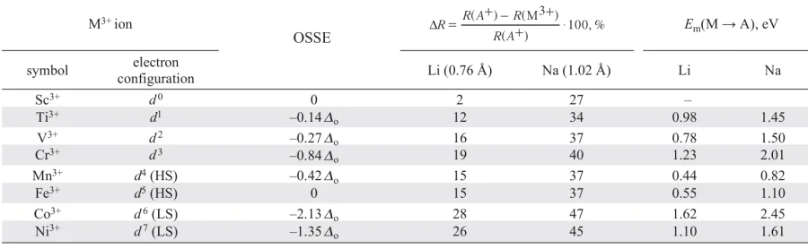
Layered lithium oxides based on vanadium, chromium, manganese, and iron have stabilization energies < 1 Do and easily can be rearranged into the spinel structure under electrochemical cycling.117 – 124 LNO oxide, as well as LCO, is the most resistant towards the O3 → spinel transformation. Apparently, the stability of LNO leads to the high temperature (~150 °C) for the Li0.5NiO2 structural transformation.115 The difference between the ionic radii of Co3+ and Ni3+ cations vs. Li+ radius (see Table 3) are the largest for the whole series of transition 3d-metals. This feature makes a certain contribution to the stability of the layered structure with respect to spinel for LCO and LNO.
The transformation of LNO into the cubic NiO structure requires the reduction of nickel cations to the divalent state (due to the loss of oxygen) and the migration of Ni2+ from their positions into octahedral vacant voids formed during the lithium deintercalation. This kind of migration is possible due to the proximity of the ionic radii of Ni2+ (0.69 Å) and Li+ (0.76 Å), in contrast to the smaller Ni3+ cation (0.56 Å). The presence of oxygen vacancies in the octahedral coordination environment of Ni2+ significantly lowers the energy barrier to its migration into the neighboring tetrahedral void (by ~ 50% for one vacancy and ~ 70% for two vacancies), which facilitates the transition of nickel into unoccupied lithium positions.125 Oxygen release is associated by the thermodynamic instability of the H3 phase (i.e., the H2 → H3 phase transition).126, 127 There are evidences 128, 129 that oxidation of the anionic sublattice results in a reactive singlet form of oxygen, 1O2, reacting with the electrolyte to form CO and CO2. The formation of oxidized forms of oxygen is possible throughout the material, but due to the high kinetic barriers of O – O dimer formation and diffusion of molecular oxygen in the LNO structure, oxygen releases from the surface layer.125
Upon transformation of the layered structure into spinel and into the cubic structure of NiO, the number of crystallographic positions available for lithium decreases and, accordingly, the electrochemical capacity decreases.130 The mobility of lithium cations also decreases, since the presence of nickel cation in the lithium position leads to a local reduction in the distance between neighboring oxygen layers.131 The surface of the active cathode material particles undergoes significant structural rearrangements.125, 132 – 134 As a result, lithium diffusion is blocked and electrical resistance increases (NiO is an insulator).
If we compare layered lithium oxides and their sodium analogues with the O3 structure, the latter are more stable towards transformation into the spinel structure. This is explained by the much larger ionic radii of Na+ than Li+ (see the Ref. 16) and its inability to occupy tetrahedral voids.116 During electrochemical cycling the layered sodium oxides are also significantly more stable to cation disorder, which is confirmed by much higher values of the anti-site defect’s formation energies and migration barriers of the transition metal cation into the alkali metal layers (Fig. 27).69, 135
![[{"id":"z5PIO48gpq","type":"paragraph","data":{"text":"Anti-site defect in the O3-type structure. The formation energies of anti-site defects in nickel-containing layered lithium and sodium oxides. The figure was created by the authors of the review based on the data of the Refs 69, 135."}}]](/storage/images/resized/i975w3lf1IPyyRVSuAoCXcpMzEop8NvLmgPiIPNB_xl.webp)
4.4. Chemical modification of Ni-rich layered oxides
In terms of the prospects for the use of transition 3d-metals in the composition of layered oxide cathodes for LIBs, nickel can be considered a ‘compromise’, combining the following indisputable advantages and obvious disadvantages:
— nickel is the only transitional 3d-metal capable of giving up more than one electron in layered oxides due to the sequential oxidation of Ni2+ → Ni3+ → Ni4+;
— the placement of the valent electrons of nickel on the antibonding eg-orbitals permits to have more charge without significantly weakening the Ni – O bond; in comparison, LCO is unstable towards oxygen release at high charges;
— due to one of the highest values of the octahedral crystal field preference energy of Ni3+ among trivalent transition metal cations, the layered structure is stabilized towards transformation into spinel-like and rock-salt structures;
— nickel is cheaper, more accessible and less toxic than cobalt;
— Ni3+ and Ni4+ cations exhibit the properties of strong oxidizing agents, which leads to the instability of Ni-rich layered oxides in relation to moisture, therefore, handling them must be done in dry rooms;
— highly delitized Ni-rich layered oxides are unstable towards oxygen release (especially under heating), which creates problems for safe operation of LIB;
— due to the collapse of layers in case of phase transition at high degree of charge and sharp anisotropic change of unit cell parameters, mechanical stresses arise, leading to cracks formation and cathode material destruction.
These disadvantages cause the low reliability and low cycle life of LNO, that is why such oxides have not been used in commercial LIBs so far, despite the fact that almost 70 years have passed since their discovery in 1954. Nevertheless, LNO (as well as LCO) has become the base system for numerous chemical modifications in order to level out its inherent disadvantages while preserving, if possible, its advantages (Fig. 28). Chemical complexity increases electrochemical capacity, reducing cost, improving safety, and the cycle life of LIBs, but not all of these goals can be achieved simultaneously and the result will always be a compromise depending on the specific application.
![[{"id":"qQR0_UzDPI","type":"paragraph","data":{"text":"The stages of modification of cathode materials based on nickel-containing layered oxides for LIBs. The figure was created by the authors of the review based on the data of Refs 136 – 145."}}]](/storage/images/resized/2fm9vVFP0PfEIerbfhSpOTI1UBBxtdfnyx8LoIe1_xl.webp)
A wide range of functional characteristics for such a compromise is realized in mixed oxides LiNixMnyCozO2 (x + y + z = 1; these oxides are also denoted as NMCXYZ, where X : Y : Z is the molar ratio of Ni, Mn, and Co) due to the extensive homogeneity region of the O3 structure at varying concentrations of Ni, Co, and Mn. The LCO and LNO oxides form a continuous series of solid solutions over the entire concentration range,146 which is related to the closeness of the ionic radii of the low-spin Ni3+ (0.56 Å) and Co3+ (0.545 Å) cations. Mn3+ ions are oxidized by Ni3+ cations to form the Mn4+ – Ni2+ pair (Fig. 29), which limits the maximum substitution of nickel for manganese in LNO to the composition LiNi0.5Mn0.5O2 .139, 147 Co3+ cations retain their LS configuration in Ni-rich NMCs.148 The energy levels of the Ni3+/2+ and Ni4+/3+ redox pairs (eg-states of nickel) are located higher than the Co4+/3+ redox pairs and also higher than the edges of the O 2p-band (see Fig. 29). Thus, upon lithium extraction from NMCs, cation oxidation begins with nickel ions (Ni2+ → Ni3+ → Ni4+), followed by cobalt ions (Co3+ → Co4+),149 rather than oxygen at high degrees of lithium deintercalation (x(Li) ≈ 0.85), which favors NMC layer structure retention during long-term cycling.150 Nickel, being partially in the +2 oxidation state, is able to give up two electrons while oxidizing to the +4 state, which provides a high reversible capacity.151 The energy level of the Mn5+/4+ redox pair (the t2g state of manganese) is well below the upper edge of the O 2p band, so that manganese remains electrochemically inactive.152
![[{"id":"5pNE9pDydz","type":"paragraph","data":{"text":"Schematic alignments of energy 3<i>d</i>-orbitals in layered NMC oxides. The dotted arrow shows the electron transfer corresponding to the reaction Mn<sup>3+</sup> + Ni<sup>3+</sup> → Mn<sup>4+</sup> + Ni<sup>2+</sup>. The order of electron extraction is reflected by Roman numerals I – III. The figure was created by the authors of the review based on the data of the Refs 151, 152."}}]](/storage/images/resized/WJp4si7tMad7wY7kNCc1IaCeWB7XoIA4svWCvEal_xl.webp)
The low-spin Co3+ cation exhibits a propensity for octahedral coordination even greater than Ni3+ (see Table 3), so the substitution of nickel for cobalt increases the resistance of the layered structure to cation migration.153, 154 The introduction of cobalt into the LNO structure also prevents the ordering of lithium vacancies and contributes to the suppression of monoclinic distortion during electrochemical cycling. This leads to a smoothing of the charge-discharge curves upon (de)intercalation of lithium from cobalt-containing LNO. The LiNi1 – xCoxO2 composition with cobalt concentration of 20 – 30 at.% (reversible discharge capacity 190 mA h g–1) is optimal regarding electrochemical characteristics.146 Manganese addition improves the thermal stability of NMC-based cathode materials due to stronger bonding of Mn4+ ion with oxygen.155 However, with the introduction of Mn4+, the structural resistance to cation migration deteriorates because the octahedral coordination preference energy for Mn4+ ( – 0.84 Δo) is inferior to that of nickel and cobalt. The influence of nickel, manganese, and cobalt on various characteristics of NMC at the qualitative level is reflected as follows:10 resistance to cation migration and electrical conductivity Co > Ni > Mn; resistance to oxygen release, prevalence in the Earth’s crust, and environmental friendliness Mn > Ni > Co.
The influence of the ratio of nickel, manganese, and cobalt on the specific discharge capacity, electrochemical cycling stability, and thermal stability of NMC is illustrated in Fig. 30.144, 156, 157 As in the case of LNO, practical application of cathode materials with high nickel content (x ≥ 0.8) with significantly higher electrochemical capacity (up to 220 mA h g–1) compared to, for example, NMC111 (160 mA h g–1) is severely limited due to high capacity loss under electrochemical cycling with extraction of more than 80 – 90% of lithium and low thermal stability, which reduces the safety of battery operation.144, 156, 157 The reasons for the deterioration of the characteristics of Ni-rich NMCs are closely related to the above-described phase transition H2 → H3 in LNO during (de)intercalation of lithium, for which the values of potentials depend on the nickel content in NMCs. Indeed, a comparison of the dQ/dV peaks on the differential charge-discharge curve as a function of chemical composition (i.e., x, y, and z values in the NMC formula) shows that the potentials for the H1 → M and M → H2 phase transitions do not change much, while those for the H2 → H3 phase transition decrease with increasing nickel content.127 For example, the H2 → H3 phase transition occurs at > 4.6 V vs. Li+/Li for NMC622, NMC523, and NMC111, while at the same time this transition is observed at ~ 4.3 and ~ 4.2 V for x = 0.8 and 0.9 and ~ 4.0 V for LNO (Fig. 31).
![[{"id":"1QUyOr15Km","type":"paragraph","data":{"text":"Specific discharge capacity, thermal stability and capacity retention as a function of NMC composition. The target in the upper right corner indicates the desired electrochemical parameters for the NMC. Figure created by the review authors based on data from the Refs 144, 156."}}]](/storage/images/resized/xQRFyf8MjAxL2qO1vBAZOaVAGxmfevToLWNh8HpQ_xl.webp)
![[{"id":"48HUrkr_3Z","type":"paragraph","data":{"text":"Cyclic voltammograms for NMC622 (<i>a</i>) and NMC811 (<i>b</i>). The figure was created by the authors based on archive materials for the Ref. 158."}}]](/storage/images/resized/vEVkLlyiBs6tO9CIrDHwl8PbF0QK1L2ojQj4tZfF_xl.webp)
Deformation of the crystal lattice leads to the appearance of mechanical stresses in the electrode structure, and eventually to the violation of the mechanical integrity (cracking) of crystallites, i.e. to the degradation of the material.77, 159
To increase cyclic stability and thermal stability, the introduction of a small amount (from fractions to units of at.%) of a doping element into the cationic sublattice of Ni-rich layered oxides is widely used. Ni-rich NMCs doped with cations of various elements (Mg, Zr, Ti, Al, Ga, W, Mo, Ta, Si, Cr, Fe, etc.),156, 160 – 166 as well as multicomponent systems with two (e.g., Co and Ga, Co and Al, Co and Ti, Co and Mg, Mn and Co, Mn and Mg, Mn and Ti),167 and even three doping cations have been extensively studied.168 In many cases, significant improvements in capacity retention and thermal stability have been demonstrated at doping element contents of 1 to 5 at.%. This makes extremely difficult the unambiguous identification of dopants in the structure of Ni-rich NMCs by standard methods of powder X-ray diffraction and/or X-ray energy-dispersive analysis.161, 166, 169 – 172 Doping levels of 10 – 20 at.% can improve the cyclability and thermal stability of such materials, but significantly reduce their electrochemical capacity.173 – 178
The doping of Ni-rich layered oxides with Al3+ cations has been the most successful in terms of industrial applications, and has resulted in the development of LiNixCoyAlzO2 (NCA) cathode materials. Aluminum can replace up to 25% of nickel in LNO.179, 180 However, due to the electrochemical inertness of Al3+ cations, which leads to a loss of electrochemical capacity, the concentration of aluminum in the structure is usually quite low — not more than 5 – 6 at.%.181 – 184
The LiNi0.8Co0.15Al0.05O2 composition was found to be the most promising for commercialization: with further increase in nickel content, there is a slight increase in specific electrochemical capacity, but the cyclic stability decreases (Fig. 32).185 The initial NCA composition was gradually changed over time to increase the nickel fraction (LiNi0.84Co0.12Al0.04O2).186 The positive effect of Al3+ appears to be due to the formation of a strong bond with oxygen due to the strong overlap of the Al 3s- and O 2p-orbitals and the resulting additional stabilization of the partially delithiated layered structure.187 Aluminum doping shortens and strengthens the Ni – O bond, which also has a positive effect on the material’s resistance to oxygen release and increases thermal stability.184 Moreover, it has been experimentally shown that aluminum prevents the collapse of layers at high charge degrees and improves the mechanical stability of the cathode.188
![[{"id":"KYnTMQhSCe","type":"paragraph","data":{"text":"The effect of nickel content on specific discharge capacity and capacity retention (after 100 cycles) for NMC and NCA. The three numbers at each point represent the molar ratio <i>x : y : z</i> in NMC and NCA.<sup>185</sup>"}}]](/storage/images/resized/y6OIQ16KWlHv26K0NHGaMkLcWsWyECAxlJ4NXntY_xl.webp)
4.5. Synthesis of nickel-containing layered cathode materials
The critical parameters of cathode materials based on NMC layered oxides are presented in Table 4. In addition to main electrochemical characteristics (discharge capacity at different current densities, Coulomb efficiency of the first charge-discharge cycle, cycle life), which depend on the chemical composition of Ni-rich layered oxides, cathode materials must meet the following requirements.
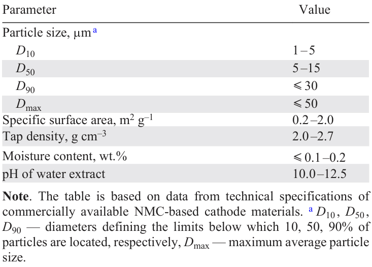
1. The distribution of transition metal cations and dopants through particles of cathode materials should be homogeneous. This is critical for achieving the calculated electrochemical capacity and cycle life of NMC and NCA. The segregation of manganese in NMC has a particularly negative effect, leading to the formation of domains of Li-enriched phases, which are electrochemically inactive in the operating potential range. At the same time, depletion of the remaining part by manganese lowers the structural stability of the material during electrochemical cycling.
2. Tap density, which characterizes the ability of the cathode material to compact upon applying the electrode layer and its compaction on the roll press (the LIB energy density depends on it), should be high. Tap density is directly determined by the shape, size and porosity of the particles, as well as by the adhesion forces between them, determined by the surface roughness. A high tap density requires the particles to be predominantly spherical in shape, which allows for dense packing during shaking.
3. The particle size distribution is set depending on the desired electrode layer thickness. For LIB cathode thicknesses from 25 to 75 μm,189 the optimal particle sizes are in the range from 5 to 15 μm.190 Large particles with D > Dmax (see Table 4) are highly undesirable, as they result in inhomogeneities and disruption of the electrode layer integrity.
4. The specific surface area of the cathode material should be small. This parameter determines the contact area of the material with the electrolyte and, consequently, the amount of electrolyte required for its wetting, and also affects the cyclic stability (due to side reactions with the electrolyte). In addition, a high value of specific surface area increases the solvent consumption in the creation of the electrode mixture.
5. The moisture content should be low. This is critical for cycle life of the battery because the water catalyzes the decomposition of the cathode material. For example,

6. The pH value of the aqueous extract should correspond to a slightly alkaline medium. This value characterizes the amount of residual surface lithium carbonate and/or lithium hydroxide, which create a passivating film that increases the impedance of the LIB. In addition, excess LiOH degrades the polyvinylidene fluoride used as a binder in the cathode material.191
7. Impurities should not exceed acceptable concentrations. Impurities of metal cations (Fe, Cu, Na, Zn, Ca) and sulfate and chloride anions are usually normalized.
The synthesis method should provide obtaining cathode material satisfying the above requirements. The synthesis ways and conditions of layered oxide cathode materials directly affect their physical and chemical properties and electrochemical parameters.38, 192 – 194 Methods based on chemical co-precipitation, aerosol pyrolysis, spray drying, as well as solid-state, hydro- and solvothermal synthesis and sol-gel methods have been widely studied. Currently, the most common and preferable method for industrial production of NMC and NCA cathode materials is the method based on co-precipitation of mixed hydroxide precursor (NixMnyCoz)(OH)2 (where transition metals are in oxidation state +2), followed by high-temperature annealing with a lithium source (LiOH, Li2CO3).195 In this method, the problems of chemical homogenization and agglomeration are solved simultaneously — by precipitation of a mixed precursor with homogeneous distribution of transition metal cations from soluble salts in the presence of a complexing agent. Parameters such as pH, temperature of the reaction mixture and atmosphere in the reactor, sources and content of transition metals, nature of the complexing agent and its concentration, reagent feed and stirring rates, and mixing method affect the nucleation and growth of particles, and hence their morphology, as well as the phase and chemical compositions of the cathode materials.196 – 198 In addition, the particle morphology and characteristics of the final cathode material are also influenced by the atmosphere (air, oxygen, inert), duration, temperature, and number of high temperature annealing steps with the lithium source.196, 199 – 201 Compared to the methods described in the literature using carbonate or oxalate precursors,194 this technique produces polycrystalline material in the form of spherical agglomerates with an average diameter of 5 – 15 μm, consisting of primary particles < 0.5 μm in size, with a relatively high value of tap density (~ 2.0 – 2.5 g cm–3) (Fig. 33a).201
![[{"id":"bEbei1iIAJ","type":"paragraph","data":{"text":"SEM images of the agglomerate consisting of primary particles (<i>a</i>) and non-agglomerated with each other single-crystal particles (<i>b</i>) of the cathode material based on Ni-rich NMC. The figure was created by the authors based on archive materials for the Ref. 158."}}]](/storage/images/resized/c8KoxczpPkGE6Q7jtayvklZBuk0tyePNouPocPQN_xl.webp)
The raw reagents used in hydroxide co-precipitation are cheap and water-soluble transition metal sulfates. These salts are used in the chemical industry more often than nitrates, acetates, and chlorides.194, 200 An additional positive effect of using sulfates arises from residual SO42– ions in the co-precipitated precursor, which interact with the lithium source to form amorphous Li2SO4 at the grain boundaries of the layered oxide,202 which increases the mechanical stability of the agglomerates during the charge (discharge) process and increases the cycle life. Transition metals are present in aqueous solutions as hydrated ions M2+aq (octahedral complexes [M(OH2)6]2+). Aqueous solutions of sodium hydroxide and NH3 – H2O are chosen as precipitant and complexing agent, respectively. The complexation reaction of ammonia with transition metal ions in aqueous solution plays a fundamental role in the co-precipitation of nickel, manganese and cobalt hydroxides.
Consistent decrease of ionic radii and increase of solubility product (SP) values from Mn(OH)2 to Co(OH)2 and Ni(OH)2 occurs when shifting along the 3d-metal series (Table 5). Nickel forms ammonium complexes much more easily than manganese and cobalt: the values of the stability constants of ammonium complexes increase significantly as one shifts down the 3d-metal series (see Table 5). Using complexing agent NH3 – H2O, it is possible to control the equilibrium concentrations of M2+ in solution and prevent separate precipitation of hydroxides with different solubility due to the formation of complexes of transition metals with ammonia in solution
which enter into a substitution reaction with the formation of mixed hydroxide

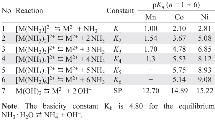
A certain concentration of ammonia, which depends on the ratio of Ni2+ : Mn2+ : Co2+ cations, is necessary for the formation of divalent nickel, cobalt and manganese amino complexes simultaneously existing in solution.
It should be noted that the stability of manganese(II) amino complexes is very low: hexaamino manganese(II) ions can be fixed only in ammonia solution with a concentration above 1–2 mol l–1. The amphoteric character of manganese(II) hydroxide manifests itself in the ability to form anionic hydroxo complexes [Mn(OH)3]– in highly alkaline medium (pH > 14). The region in which co-precipitation of the mixed precursor occurs is determined by the range of pH values of the medium corresponding to the stability of Mn(OH)2 , which ranges from 7.2 to 14.0 at 50 °C, according to the Pourbaix diagram (diagram of predominant forms or E — pH diagram)* for the Mn — H2O system (Fig. 34). In addition, the region of existence of Mn(OH)2 in the Pourbaix diagram lies significantly below the E – pH relation for the oxygen reduction reaction
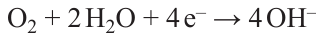
![[{"id":"IhexyUfjwc","type":"paragraph","data":{"text":"Pourbaix diagram for the Mn – H<sub>2</sub>O system (without taking into account the formation of Mn<sup>II</sup> amminocomplexes). Dashed lines define <i>E</i> – pH dependences for the reactions O<sub>2</sub> + 2 H<sub>2</sub>O + 4 e<sup>–</sup> → 4 OH <sup>–</sup> and 2 H<sub>2</sub>O + 2 e<sup>–</sup> → H<sub>2</sub> + 2 OH<sup>–</sup>. The figure was created by the authors of the review based on data from the Ref. 205."}}]](/storage/images/resized/aBb1mmnwl5jhaVmPJtqSVUzLv4IsW6snbXA86nXV_xl.webp)
Therefore, Mn(OH)2 is prone to oxidation by air oxygen to form compounds MnIII and MnIV (see the Ref. 204). Cobalt(II) amino complexes are also unstable to oxidation: in air they transform into cobalt(III) ammonium complexes. It follows from the E – pH diagrams of the systems Co(Ni) – H2O – CO2 (see the Ref. 205) that CoCO3 , unlike NiCO3, becomes stable relative to Co(OH)2 already at very low CO2 content. Finally, due to the structural similarity of M(OH)2 hydroxides and MOOH oxohydroxides, as well as the ease of phase transformations206

The slightest deviations of pH, p(O2), and synthesis temperature from the optimal values can lead to the formation along with (NixMnyCoz)(OH)2 impurity in the form (NixMnyCoz)OOH, in which the oxidation state of transition 3d-metals differs from +2, which will adversely affect the electrochemical properties of the final cathode material. Thus, the co-precipitation of mixed hydroxides should be carried out under strict control of the acidity of the medium and temperature in an inert gas atmosphere (e.g., argon or nitrogen) in the absence of O2 and CO2 to avoid segregation of transition metals and the formation of impurity phases (MCO3 , MOOH).
Based on numerous experimental data on the dependence of particle size and morphology on the duration of co-precipitation, pH of the reaction mixture, and NH3 – H2O concentration,207 as well as the results of the analysis of the corresponding chemical equilibria, the authors of the Refs 198, 203 proposed a mechanism for the growth of dense spherical particles in the presence of aqueous ammonia solution;, which is schematically represented in Fig. 35. One can divide the growth process of spherical secondary agglomerates into two stages: nucleation and agglomeration, i.e., growth of secondary particles. Transition metal ions, NaOH and NH3 – H2O, getting into the reaction vessel, form a large number of nucleates, which grow under conditions of dynamic equilibrium between metal hydroxide particles and aqueous ammonia solution (see equations (11) and (12)).
![[{"id":"JTRe_E2SaU","type":"paragraph","data":{"text":"The scheme of nucleation and agglomerate formation and growth during co-precipitation of the hydroxide precursor M(OH)<sub>2</sub> . The figure was created by the authors of the review based on the data of the Refs 198, 203."}}]](/storage/images/resized/SN7Fxr2pS6B4srodXgvM1DunA7iQ9EAEZ1gJWmHe_xl.webp)
Particle growth includes two stages: diffusion of substance to the surface of the particle and its crystallization (see Fig. 35). At the growth stage, nuclei colliding with each other form primary particles, on the surface of which smaller nuclei are continuously adsorbed. The resulting particles continue to grow during aging and recrystallization of small crystals. The crystals dissolve and are re-deposited during recrystallization. The recrystallization rate depends on the ratio of the rates of both processes, i.e. it depends on the precipitate nature and precipitation conditions. The rate of the whole process increases with increasing solubility, hence increasing the synthesis temperature promotes recrystallization.
One of the processes occurring during recrystallization is Ostwald ripening — the transfer of matter from small particles to large particles — in which the competition between precipitation and complexation has a great influence on the growth of secondary agglomerates. Thus, the formation of a single-phase mixed precursor with homogeneous distribution of transition metals on particles with spherical morphology is significantly affected by the ratio of [M(NH3)n]2+ and OH– (in other words, the pH value of the reaction mixture determined by the content of NaOH in it) and the concentration of the complexing agent, which together affect the surface energy of the particles.
Stirring speed determines to a large extent the morphology and size of agglomerates, as this process can accelerate the collision of primary particles with each other, as well as with the walls of the reaction vessel, which promotes the formation of denser spherical particles. At the same time, too high a stirring speed (> 1000 – 1200 r min–1), which depends on the design of the reaction vessel, can lead to deformation and (or) cracking of particles.208 Increasing the synthesis temperature to 50 – 55 °C also promotes the formation of a single-phase mixed precursor with a homogeneous distribution of transition metals through particle with a given morphology.194
Mixed hydroxide M(OH)2, isostructural β-Ni(OH)2 (sp. gr. P3̅ m1) with hexagonal layered structure like brusite Mg(OH)2 is obtained by co-precipitation method. In the structure of M(OH)2 hydroxide ions form the closest hexagonal packing, and transition metal ions occupy octahedral voids.209 – 211 The crystal structure of β-Ni(OH)2 is built of layers formed by octahedra of Ni(OH)6 , which are connected by common edges. The interaction between the layers is realized by van der Waals forces and hydrogen bonds (Fig. 36a,b). Along with β-Ni(OH)2 there is a more ‘loose’ α-form of this hydroxide, in which interlayer water molecules are located between the Ni(OH)2 layers (Fig. 36c). Due to this, the interlayer distance is significantly increased (from 4.6 to 8 Å), which in turn leads to additional disorder in the stacking of the layers. The α-form consists of layers of disordered octahedra in which there is a deficiency of OH-groups, i.e. the composition of the nickel-containing layer is described by the formula [Ni(OH)2 – x]x+. Anions can also be introduced between the layers to compensate the positive charge,212 – 214 so the general formula of the α-modification can be written as [Ni(OH)2 – xAn–x/n · y H2O], x = 0.2 ÷ 0.4, y = 0.6 ÷ 1, A = Cl –, NO3 –, SO42 –, CO32 –. The α-modification of Ni(OH)2 is unstable under co-precipitation conditions of mixed hydroxide precursor (elevated temperature and presence of NaOH) and converts to β-Ni(OH)2. The molecular water is easily removed by heating to 100 – 150 °C.215, 216 Examples of layered phases consisting of structural motifs of α- and β-forms can be found in the literature.146, 217 – 219 The precursor structure affects the electrochemical properties of the final cathode material. For example, NMC622 obtained from mixed α – β precursor shows higher capacity at high current densities up to 5C (1C corresponds to charge(discharge) for one hour), and the material obtained from precursor with β-structure shows better cycle life.220
![[{"id":"swEVjNwZgB","type":"paragraph","data":{"text":"Crystal structure of β-Ni(OH)<sub>2</sub> (<i>a</i>), schematic representation of ordered (<i>b</i>) and disordered (<i>c</i>) modifications of Ni(OH)<sub>2</sub> . The figure was created by the authors of the review on the basis of the data of Refs 209 – 211."}}]](/storage/images/resized/iKW1iNoICvPV15t0yqqs4H83ZIo2m2kC19uuoWjh_xl.webp)
Homogeneity of transition metal distribution and spherical agglomeration of particles achieved at the precursor formation stage are maintained at the subsequent stage of solid-state synthesis of the final cathode material. At the stage of high-temperature annealing with a lithium source, the layered crystal structure of the mixed oxide is formed and its degree of anti-site defectivity (the degree of transition metal cations in the lithium layers) is laid down, on which the electrochemical capacity and transport of Li+ cations depend (see Section 4.3.3). The anti-site disorder of Li and M can be described using the Kröger-Wink notation

where Ni×Ni is the Ni2+ cation occupying its regular position; Li×Li is the Li+ cation occupying its regular position; Li'Ni is the Li+ cation occupying the Ni2+ position and having one relative negative charge; Ni•Li is the Ni2+ cation occupying the Li+ position and having one relative positive charge.
The chemical composition of the layered oxide is preserved at anti-site disorder, but in fact the ratio of lithium and transition metal ions is not constant and depends on the oxygen partial pressure as well as the temperature at the last stage of solid-state synthesis.221 Since in LiNixMnyCozO2 with high nickel content x > y, electroneutrality is achieved by partial oxidation of Ni2+ to Ni3+. As the partial pressure of oxygen decreases, it leaves the lattice into the gas phase, the reduction of trivalent NiNi and its migration to the lithium position NiLi with annihilation of nickel and oxygen vacancies occur, which corresponds to the transformation of the layered LiMO2 structure into a rock-salt-type MO structure
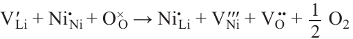
where V'Li is a Li+ vacancy having one relative negative charge; O×O is an O2– anion occupying its regular position; V'''Ni is a Ni3+ vacancy having three relative negative charges; VO is an O2– vacancy having two relative positive charges. The partial reduction of Ni3+ to Ni2+ increases the nickel concentration in the lithium positions. An excess of trivalent nickel can be formed at too high oxygen partial pressure, and it is compensated by lithium cations in the nickel position 222

here, the oxygen molecule creates two crystallographic positions Li'Ni and Li×Li , which are populated from the lithium source Li(s) , and the charge is compensated by the oxidation of Ni×Ni → NiNi .
The temperature and partial pressure of oxygen can be expressed by the change of chemical potential of oxygen

At constant pressure, the temperature dependence of Δμ(O) is almost linear. As for Δm(Li), it can practically be controlled by the lithium concentration excess. The phase diagram of the Li – Ni – O system in a space of oxygen and lithium chemical potential changes at atmospheric pressure is presented in Fig. 37. The diagram was constructed using data on the DFT calculated formation energies of the main phases of this system.223 As can be seen, the LNO phase has a rather narrow stability region, so its synthesis should proceed under strictly controlled conditions to prevent the formation of other nickel oxides (LiNi2O4 , NiO and Li2NiO3). It should also be noted that the maximum temperature of LNO synthesis regardless of the value of Δμ(Li) is 980 K at atmospheric pressure (p(O2) = 0.2 atm, Δμ(O) = –1.14 eV).
![[{"id":"WtDz7o5qO5","type":"paragraph","data":{"text":" Phase diagram of Li – Ni – O in a space of oxygen and lithium chemical potential changes. The red line corresponds to Δμ(O) at 300 K and atmospheric pressure. The figure was created by the authors of the review based on the data of the Refs 69, 223."}}]](/storage/images/resized/kQo5FsE3Vl3i7gPLCBDSAwKecgXcmjT8Wh95aGyO_xl.webp)
We emphasize that controlling the stoichiometry of Ni-enriched NMCs requires both the correct choice of annealing temperature and oxygen partial pressure, which determine the thermodynamic equilibrium, and optimization of the microstructure of mixed hydroxide precursors, the search for the most suitable lithium source, the optimal ratio between the amounts of precursor and lithium source, the conditions of their mixing, as well as the heating (cooling) rate.
The most promising methods to reduce surface passivation of cathode material particles caused by cation migration and interaction with the electrolyte are considered to be the application of protective surface coatings,224 – 226 creation of materials with a core-shell structure,227, 228 with a concentration gradient. In the latter particles, the concentrations of nickel and manganese gradually change (i.e., high nickel content in the core and lower nickel content on the surface).227, 228 Various variants of such cathode materials are also used — with a full concentration gradient, with a two-stage concentration gradient, with a shell gradient in the core-shell structure, etc.228 – 231
An approach alternative to the production of polycrystalline agglomerated Ni-rich NMCs is the creation of materials in the form of individual, not agglomerated with each other large crystal particles of ≥1 μm in size (so-called single crystals) (see Fig. 33b). Such particles are less susceptible to degradation of specific capacitance due to a much smaller contact area with the electrolyte than their polycrystalline analogues. Single crystals with particular morphology can provide higher tap density (> 3.0 g cm–3) along with electrochemical stability compared to polycrystalline materials, which is critical for the development of more compact batteries than existing ones.158, 232 The most preferred approach for obtaining single crystal is the use of easily melting inert salts (fluxes) or their eutectic mixture during high-temperature annealing of a mixed precursor and lithium source. On the one hand, since this approach involves several steps of heat treatment at high temperatures as well as washing off the flux components, this synthesis method is labor-, time-, and energy-consuming.158 On the other hand, the morphology of the single crystals can be controlled by varying the synthesis parameters (chemical potential of lithium and oxygen), which opens a wide range of possibilities for the targeted design of many cathode materials to improve their electrochemical characteristics.158
* Diagram visualizing the thermodynamically stable forms of existence of elements (ions, molecules, atomic crystals, and metals) in solutions at different values of pH and redox potential E.
5. Conclusion
Nickel does not possess a set of record-breaking characteristics as a basis for layered oxide cathode materials for LIB (for example, it is inferior to cobalt in the layered structure stability towards cation migration, and to manganese in the oxygen bonding strength), but it is a unique ‘compromise’ in a number of parameters which are crucial for the creation of commercially successful LIBs (Fig. 38).
![[{"id":"B59oN9G5ng","type":"paragraph","data":{"text":"Place of nickel among transition 3<i>d</i>-metals in the context of creating layered oxide cathode materials for LIBs. The figure was created by the authors of the review based on the data of the Refs 10, 18 – 21, 24, 76, 152, 232."}}]](/storage/images/resized/V8gt65huEnoLv8wL77uq7iJBxXvnJbobtxwaCjvl_xl.webp)
The investigations of Ni-rich layered cathode materials with promising properties for high energy density LIBs for electric vehicles have shown that by now the potential for further improvement of these materials by changing the chemical composition and crystal structure has been practically exhausted. At the same time, an understanding has been reached that the functional characteristics of the material, along with the properties of elements, the nature of chemical bonding, crystalline and electronic structure, depend on the nature and number of point and extended defects, mechanical and electrical transport properties of intergranular boundaries, morphology of primary particles and agglomerates that determine the diffusion paths, structure and resistance of different types of surfaces to side reactions. The formation and evolution of the defects and morphological features during electrochemical cycling must be taken into account in addition to their formation during material synthesis. Within such a context, the complex hierarchical structure of Ni-rich layered cathode materials can be considered as a ‘window of opportunity’ for further improvement of functional properties.
Polycrystalline agglomerates of Ni-rich layered cathode materials are unstable to mechanical stresses, which leads to their gradual destruction during battery operation, since the volume of particles changes significantly during electrochemical (de)intercalation of lithium. As a result of the formation of cracks and, as a consequence, new surfaces, the surface area to volume ratio changes, which deteriorates the material properties due to different mechanisms of chemical and structural degradation on the surface and in the bulk of the particles. The crack resistance of polycrystalline materials, critically dependent on the size, shape, and preferential orientation of grains,233 differs greatly for the two main variants of microstructural organization of spherical agglomerates:
— with high isotropy of grain sizes and their random orientation relative to each other and to the surface of agglomerates,
— with strong grain size anisotropy in the form of rods or columnar elements and expressed mainly in radial orientation (Fig. 39); the radial organization of agglomerates increases fracture resistance and is considered preferable for capacity retention at high charge (discharge) rates because of the orientation of lithium diffusion channels predominantly from the center to the periphery of the agglomerates.229, 234, 235
![[{"id":"K3L--ohviF","type":"paragraph","data":{"text":"Microstructures of Ni-rich NMC agglomerates with random orientation of isotropic particles (<i>a</i>) and with radial orientation of rod-like particles (<i>b</i>) and their evolution during electrochemical cycling. The figure was created by the authors of the review on the basis of the data of Ref. 234."}}]](/storage/images/resized/v8XqaVSwlgzk6O4pXBlJvwK5yOQ4RFcinig4hiA8_xl.webp)
It is well-known that agglomerates with anisotropic radially oriented particles are formed if one sets a nickel concentration gradient from the center to the periphery of the agglomerate during co-precipitation.229, 236 However, this results in nickel-rich core structures with isotropic particles, as well as an undesirable combination of compression and expansion strains. Another possibility is based on ‘manipulating’ the relative energies of different crystallographic surfaces, which can be achieved by varying the oxygen partial pressure and chemical potential of lithium during high-temperature lithiation of precursors,237 by varying the concentration of antistructural defects,69 and by doping with elements that selectively segregate on the crystal surface, such as boron.238, 239 Thus, the microstructure design of Ni-rich NMC cathode materials is a complex multifactorial challenge, the solution of which can lead to a significant increase in their life cycle.
Extended defects in crystal structure are also not neutral in terms of the electrochemical behavior of cathode materials, as they can lead to local inhomogeneities in the lithium distribution during charge (discharge), which causes mechanical stresses and crack formation in the primary crystallites.240 The appearance of cracks is directly related to the formation and movement of edge dislocations caused by the loss of cathode matter during electrochemical cycling,241 or to the sliding of densely packed layers relative to each other, which causes mechanical delamination.242, 243 Such intra-grain cracking is the main cause of degradation of large-crystalline cathode materials. Certain prospects for improving the mechanical stability of particles of layered cathode materials are provided by the usage of epitaxial stabilization, when coherent inclusions of disordered structure such as sodium chloride are created in the matrix of the layered structure, preventing the collapse of layers and a sharp change in volume during phase transitions.244, 245
The use of other classes of nickel-based cathode materials for LIB, such as polyanionic compounds or high-voltage spinels, involves a number of problems due to the high potentials of Ni(n + 1)+/Nin+ redox pairs. Overcoming these problems will require the development of new electrolytes with an extended zone of electrochemical stability. Such electrolytes can be created on the basis of superfluorinated solvents (e.g., 1 M solution of lithium hexafluorophosphate in a mixture of fluoroethylene carbonate, 3,3,3,3-fluoroethyl methyl carbonate, and 1,1,2,2,2-tetrafluoroethyl-2',2',2'-trifluoroethyl ether, the ratio of the last three components is 2 : 6 : 2 by mass).246, 247 This will help to fully realize the advantages of nickel, which consist in a possible increase in the values of specific energy density of materials based on it, compared to such cathode materials as, for example, LiFePO4. A new solid state LIB could solve the problem of electrolyte stability at high potentials, this technology is still at the initial stage of development.248
Besides, the steady growth of the share of alternative energy in electric power generation stimulates intensive development of post-lithium sodium-ion battery (SIB) technology. Despite the fact that SIBs are inferior to LIBs in specific energy density, their relatively low cost makes them promising for use in large stationary energy storage devices designed to smooth out over time the imbalance of generation and consumption in power grids with unstable generation. In turn, layered Ni-containing oxides, such as P2-Na2/3Ni1/3Mn2/3O2,249 P2-NaxMn3/4Ni1/4O2,250 O3-NaNi0.5Mn0.5 – xTixO2,251 are considered as promising cathode materials for SIBs, since the presence of nickel in their composition significantly boosts the specific energy density due to the realization of the reversible two-electron transition Ni2+ ⮂ Ni4+. This technology is rather young, and its development is mainly at the stage of R&D and (or) development of the first prototypes, although there are already several startup companies declaring the start of mass production of commercial SIBs in the near future. Nevertheless, the start and rapid growth of commercial production of SIBs is quite feasible due to their huge potential (primarily due to the volume of required electrochemical storage capacity), so a rapid increase in demand for nickel is possible in the long term.
Other types of batteries using nickel compounds are less advanced electrochemical systems and cannot compete with LIBs in the electric transportation market.252 In particular, nickel-cadmium and nickel-metal hydride devices are several times inferior to LIBs in both gravimetric and volumetric energy density, as well as demonstrate significant self-discharge (20 – 30% per month). Moreover, the first mentioned batteries contain a large amount of toxic cadmium and have a memory effect, which not only reduces the practically achievable capacity, but also imposes additional restrictions on the operating parameters of the devices.252 According to forecasts by leading analytical industry market research companies (Marketsand Markets, Transparency Market Research Pvt. Ltd., The Business Research Company, Spherical Insights) the nickel-cadmium battery market size will increase to 1.7 billion USD by 2031 from 1.4 billion USD in 2021. Despite the seemingly significant growth in expected sales (+21.4% over 10 years), the annual growth rate is only ~ 2.1%, indicating that the market for such devices is already saturated. A more optimistic picture appears for nickel-metal hydride batteries, with sales in value terms estimated at 5.59 billion USD by 2027. This is up from 3.54 billion USD; in 2023 (+57.9% over 4 years or +14.5% per year). Nevertheless, the above figures pale in comparison to similar estimates of LIB demands. As mentioned in the Introduction, the market for LIB cathode materials alone will be worth up to 94.5 billion US$ by 2030, an order of magnitude larger than the needs of the nickel-cadmium and nickel-metal hydride battery industry combined.
In any case, the importance of nickel for the global economy will steadily increase over the coming decades. However, while in the recent past the increase in nickel mining and processing was driven by the ever-growing demand for this metal from the metallurgy industry, now the rapid spread of electric transportation and the associated increase in demand for electrochemical energy storage are becoming the main drivers of industry development. As a major component of the cathode material structure, nickel provides a reasonable balance between the stability, stored capacity, power and cycling stability of modern high-capacity LIBs, and its role in these systems will only increase in the future. Moreover, the explosive demand for nickel may be driven by the cumulative effect of the following different factors:
— expansion of the market for high-capacity LIBs due to the increasing number of electric vehicles;
— a further steady increase in the nickel content in LIB cathodes, with a likely shift to materials with a modified microstructure organization;
— possible expansion of the variety of classes of nickel-containing cathode materials used in commercial LIBs, supported by research and development successes in related fields (e.g., potential improvements in electrolyte performance).
The authors believe that the information and conclusions in this review will be of interest not only to materials scientists and researchers developing new materials, but also to economists, industrialists, and businessmen whose daily activities will inevitably be affected by the coming global transition to electric transportation.
This review was prepared with financial support from the Russian Science Foundation (grant No. 23-73-30003, https://rscf.ru/project/23-73-30003/).
6. List of abbreviations
CCP — cubic closest packing;
CFSE — crystal field stabilization energy;
CPS — Close-packing of equal spheres;
DFT — density functional theory;
DFT-DMFT — density functional theory with dynamical mean field theory;
DFT+U — density functional theory with Hubbard correction;
DOS — density of states;
EXAFS — Extended X-ray absorption fine structure;
HCP — hexagonal closest packing;
HS — high-spin;
JT — Jahn – Teller;
LCO — LiCoO2;
LFP — LiFePO4;
LIB — Lithium-ion battery;
LMO — LiMn2O4;
LNO — LiNiO2;
LS — low-spin;
MIB — metal-ion battery;
NCA — LiNi0.8Co0.15Al0.05O2;
NMC622 — LiNi0.6Mn0.2Co0.2O2;
NMC811 — LiNi0.8Mn0.1Co0.1O2;
NNO — NaNiO2;
OSSE — octahedral-site stabilization energy;
SEM — scanning electron microscopy;
SP — Sphere packing;
XAFS — X-ray absorption of fine structure.