


Keywords
Abstract
Research and development of solid oxide fuel cells (SOFCs) and solid oxide electrolysis cells (SOECs) are currently of paramount importance in terms of realizing hydrogen energy and carbon emission reduction programs, which many countries have committed to. Although, there are many outstanding results in the fabrication and characterization of SOFCs and SOECs with promising oxygen-ionic and proton-conducting electrolytes, conventional zirconia electrolytes are still widely used not only in a lab-scale setup, but also in the form of enlarged cells and stacks, with the experimental operation of the latter during 10 000–100 000 h. To ensure good performance stability and microstructural integrity of such multilayered cells, a special attention should be paid to the chemical activity of functional materials toward their interaction with each other, especially in long-term focus. The literature analysis has shown that many undesirable processes occur in SOFCs and SOECs with the classical pairs of zirconia electrolytes and strontium-containing electrodes, including element segregation and interdiffusion, insulating phase formation, microscopic defect appearance, and delamination. Some of these processes can be efficiently eliminated by using so-called interlayers designed from doped ceria materials. Due to their numerous beneficial functions, such interlayers have several synonymous names: blocking, barrier, buffer, or protecting layers. Herein, we review the recent progress and achievements in the fundamental and applied researches dealing with the ceria interlayers and their impact on chemistry and electrochemistry of solid oxide cells based on classical zirconia electrolytes as well as promising oxygen-ionic and proton-conducting analogs.
The bibliography includes 405 references.
1. Introduction
Solid oxide fuel cells (SOFCs) and electrolysis cells (SOECs) offer a promising basis for environmentally friendly and efficient energy conversion, addressing important challenges set in global programs on hydrogen energy and carbon emission reduction.1 – 5 More specifically, in addition to conventional SOFCs and SOECs operating on hydrogen-based compounds (electricity generation from H2 or hydrogen production via water electrolysis), carbon-involved processes can also be realized in such devices: co-electrolysis of CO2 and H2O,6 – 8 direct electrolysis of CO2,9 – 11 operation on CH4 and other chemicals,12 – 14 operation on CO and H2 ,15 – 17 and etc. Moreover, the efficiency of SOFCs and SOECs can be increased in case of hybrid power systems that is of paramount importance for various human needs.18 – 22
Conventional SOFCs and SOECs use zirconia-based electrolytes, of which yttria-stabilized zirconia (YSZ) and scandia-stabilized zirconia (SSZ or ScSZ) are the most widely used materials.23 – 25 Despite of their excellent mechanical properties, acceptable values of ionic conductivity of ScSZ, and especially YSZ, can only be achieved at high temperatures, usually above 700 °C. As a result, the corresponding SOFCs and SOECs require relatively high operating temperatures. However, under such severe conditions, solid oxide electrochemical cells suffer from a rapid degradation associated with various aspects,26 – 31 including coarsening of electrode particles, depletion of functional materials by certain elements, chemical interaction between adjusting layers. The latter is a serious issue due to cationic interdiffusion caused by chemical heterogeneity of different materials being in contact with each other. Two rational approaches have typically been used to address this issue: (1) lowering the operating temperatures by replacing ZrO2-based materials with more conductive electrolyte analogs; (2) introducing a barrier layer (or interlayer) to prevent intense chemical reactivity. While the first approach has been widely discussed in the literature,32 – 37 the second one has not received comparable attention in recent review articles.
To fill this gap, the present work overviews the fundamentals of the use of interlayers, their current progress and prospects for further research related to solid state ionics, high-temperature electrochemistry, and energy conversion technologies.
2. Chemical compatibility issues
2.1. Possible mechanisms and chemistry of the classical YSZ/LSM-containing electrochemical cells
It is rational to start a discussion of chemical compatibility by considering the classic pair of functional materials (YSZ and LSM, where LSM = La1 – xSrxMnO3 – δ). For this pair, chemical interaction is possible at elevated temperatures. This can occur with the formation of La2Zr2O7 (LZ) pyrochlore and SrZrO3 (SZ) perovskite compounds, the appearance of which is associated with a certain cationic deficiency of both LSM and YSZ origin phases.38 – 40
One of the first detailed analyses of the chemical compatibility of YSZ and LSM was provided by Roosmalen and Cordfunke in 1992.41 The authors analyzed the phase nature of LSM and YSZ mixtures as a function of the variable parameters of the strontium content in LSM (x = 0, 0.3, 0.4, and 0.6) and the yttrium content in YSZ (i.e., (ZrO2)1 – y(Y2O3)y , where y = 0.03 or 0.08). The pre-synthesized powders were mixed and calcined at various temperatures (~840 to 1480 °C) and holding times (from 110 to 596 h) for further characterization by scanning electron microscopy (SEM) or X-ray diffraction (XRD). According to the results obtained, the phase compositions of the calcined YSZ/LSM mixtures were revealed (Fig. 1a). The manganite composition was shown to have a greater effect on the phase relationship of the calcined mixtures than the YSZ composition:
(1) in the case of a low Sr content (when the chemical activity of lanthanum in LSM is high), a LZ phase was formed at temperatures of 900 °C and above;
(2) when the Sr content in LSM was high, the formation of a SZ impurity as a result of the following chemical reaction:
SrOLSM + ZrO2 YSZ → SrZrO3
took place. In this case, SZ was detected when calcined at temperatures from 1000 to 1480 °C, while LZ was also formed at very high temperatures.
![[{"id":"Dp6XMolraO","type":"paragraph","data":{"text":"Interaction features of YSZ and LSM couples: (<i>a</i>) the detected impurities phases after calcination of 3YSZ/LSM and 8YSZ/LSM mixtures. Adapted from Ref. 41, Copyright Elsevier B.V., Inc., 1992; (<i>b</i>) thickness of diffusion layer between YSZ and LSM phases after their co-calcination at various temperatures for 596 h. Adapted from Ref. 41, Copyright Elsevier B.V., Inc., 1992; (<i>c</i>) qualitative XRD analysis of powder (YSZ/LSM) mixtures fired in air at 1200 or 1350 °C for 120 h. Adapted from Ref. 38, Copyright John Wiley & Sons, Inc., 1999; (<i>d</i>) relative intensity of impurity phases depending on the LSM composition and calcination regimes. Adapted from Ref. 38, Copyright John Wiley & Sons, Inc., 1999; (<i>e</i>) estimated phase diagram of LSM and ZrO<sub>2</sub> . Reproduced from Ref. 41, Copyright Elsevier B.V., Inc., 1992; (<i>f</i>) mechanism of the LZ impurity phase nucleation and growth depending on the defectness of La<sub>0.85</sub>Sr<sub>0.15</sub>Mn<sub>y</sub>O<sub>3 ± δ</sub>. Adapted from Ref. 51, Copyright Elsevier Science B.V., 1998; (<i>g</i>) representation of chemical and morphological changes at the YSZ/LSM interface under electrolysis mode. Adapted from Ref. 52, Copyright Elsevier Ltd., 2012."}}]](/storage/images/resized/wSfc0b1STz4gIH7k8gkVA4acgoDptn2TAfrwWQd6_xl.webp)
Considering the YSZ composition, 8YSZ was found to be more chemically stable than 3YSZ, as the diffusion layer thickness (DFL) between LSM and YSZ pellets was generally lower in the former case (Fig. 1b).
By analyzing the DFL as a function of temperature and holding time, the authors estimated the kinetic parameters of the interaction. According to the results, the formation of a 1 μm LZ layer between 8YSZ and LSM (with x = 0) required ~82 kh of operation at 1000 °C. About 37 kh of operation at the same temperature was required to form 1 μm of SZ between 8YSZ and LSM with x = 0.5.
The results of work 41 were further confirmed by the data of Wiik et al.38 in 1999. They prepared similar mixtures of LSM and YSZ and analyzed the phase evaluation after calcination depending on the variable parameter of the strontium content of the manganite (x = 0, 0.3, 0.4, and 0.6). The pre-synthesized powders were mixed in a 1 : 1 weight ratio, ball milled for 24 h, pressed and, finally, sintered at 1200 or 1350 °C with different holding times (from 1 to 120 h) followed by XRD characterization. As shown in Fig. 1c,d, the lowest amount of impurity phases was found at the medium La/Sr content ratio, indicating a key role of the A-site cation activity in LSM phases. Considering these results, the authors concluded that LSM containing 30 mol.% of strontium is an optimal choice for the studied pairs, in agreement with the previous report (Fig. 1e),41 in which thermodynamic calculations were performed to evaluate the phase stability of LSM and YSZ. The second important conclusion of this work is based on the fact that the LSM phases become A-site deficient after their calcination with YSZ. This suggests an effective way of reducing the activity of lanthanum and strontium in LSM and suppressing the interaction between LSM and YSZ.
The A-site deficiency effect in LSM was experimentally verified by Stochniol et al.42 They prepared two series of manganites, La1 – xSrxMnO3 – δ and La0.95 – xSrxMnO3 – δ (x = 0, 0.1, 0.2, 0.3, and 0.4), and evaluated their chemical activity with YSZ electrolyte at ~ 1200 °C for 400 h. Their results indicate that there is no visible chemical interaction between YSZ and La0.95 – xSrxMnO3 – δ with 0.2 £ x £ 0.4, while the strictly stoichiometric manganites with x = 0.2 and 0.4 result in the appearance of impurity phases after their long-term calcination with YSZ. Numerous reports then have confirmed the reactivity of LSM and YSZ pais.43 – 50
One of the key works in the last century was performed by Mitterdorfer and Gauckler.51 They used a number of complementary techniques (high resolution transmission electron microscopy, electrochemical impedance spectroscopy, and atomic force microscopy) to characterize the interface between 9.5YSZ and La0.85Sr0.15MnyO3 ± δ (y = 0.95, 0.92, and 1.02). It was found that the defect chemistry of LSM considerably affected the nucleation and growth mechanism of the LZ phase (Fig. 1f ). In particular, the LZ layer began to form near the triple phase boundary (TPB) at relatively low temperatures and holding times in the case of Mn-deficiency (y = 0.95), when the chemical activity of the A-site cations of LSM was rather high. An increased activity of lanthanum and a trace amount of La2O3 were responsible for the immediate appearance of LZ, which grew in the in-plane direction from TPB to form a dense impurity layer, limited by bulk diffusion of zirconium ions through the LZ layer. For the slightly deficient LSM (y = 0.98), the LZ phase appeared as isolated islands at TPB, whose growth in the interface region was limited by surface diffusion of zirconium ions. Finally, for the Mn-excess composition (y = 1.02), delayed nucleation and growth of LZ occurred at TPB. The authors explain this fact by the limited surface diffusion of Zr4+- and Y3+-ions towards TPB, where Mn-doped YSZ solid solutions initially appear without the formation of impurity phases; when the chemical activity of manganese decreases to the Mn-stoichiometric or slightly deficient state, the chemical activity of lanthanum ions becomes sufficient for the formation of the LZ phase, which, however, forms near TBP and creates the so-called LZ ring covering the entire TPB region. Therefore, the formation of LZ can be effectively suppressed by reducing the sintering temperatures (down to 1100 °C) and by using the Mn-excess (or A-site deficient) LSM compositions.
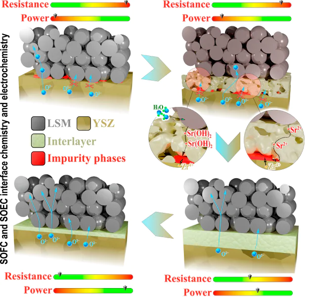
It should be noted that the interaction of YSZ and LSM leads not only to the appearance of impurity phases, but also to layer delamination under real operating conditions.52 For example, in the SOEC mode (Fig. 1g), oxygen ions arrive at the anode via grain boundary transport through the YSZ electrolyte. In the TPB region, the oxygen ions are oxidized to atomic or molecular oxygen. In the oxygen excess conditions, accelerating reactions begin to occur as shown in the following simplified reactions:
Due to these reactions, the grain boundaries develop pores, while LZ and MnO2-based phases accumulate at the interface until they completely cover the corresponding interface, causing its weakening due to mechanical stress. The experimentally observed ohmic and polarization drops of solid oxide electrochemical cells 52, 53 occur for a number of reasons: an increase in the porosity of the electrolyte grain boundaries, the appearance of low conductive impurity phases, the discrepancy between the thermal expansion coefficients (TEC) of the original and newly formed phases.
At the end of this section, several approaches can be formulated as a solution to suppress the formation of the undesirable impurity phases between YSZ and La(1 – x) – ySryMnO3 – δ:
(1) material science approaches are based on reducing the chemical activity of La3+-ions. This can be achieved by the partial replacement of La3+-ions with Sr2+ ones to a rational degree (typically, up to y = 0.3) and/or the creation of a slight A-site cation deficiency (x ≤ 0.1);
(2) technological approaches are based on the creation of well-adhered LSM-containing electrodes over the electrolyte surface at as low sintering temperatures as possible.
2.2. Other cases of chemical compatibility issues of zirconia electrolytes and electrode materials
Beyond the classic YSZ and LSM examples, similar incompatibility issues take place at elevated temperatures for zirconia-based electrolytes and other potential electrode materials.
One of the first studies using Mn-free electrodes was reported by Uchida et al.54 They tested La0.6Sr0.4CoO3 – δ (LSC) as an electrode for the 8YSZ electrolyte. A SDC interlayer was successfully used (SDC is the samarium-doped ceria, Ce0.8Sm0.2O2 – δ) to suppress the formation of La2Zr2O7 and SrZrO3 phases, appearing at lower sintering temperatures (~1000 °C) than that of YSZ and LSM pair.55 Such a tactic allowed to obtain the low polarization values of the LSC electrode (below 0.25 Ω cm2 at 800 °C and below 0.10 Ω cm2 at 900 °C), although no comparison with SDC-free electrochemical cells was made. The following works confirm the advantageous function of the SDC layer for similar systems.56 – 58
Simmer et al.59, 60 used (La,Sr)FeO3-containing electrode materials (LSF) and found that no impurity phases were detected in the calcined LSF/YSZ mixtures at 1000 °C. However, a detailed analysis of the XRD patterns revealed a significant dissolution of zirconium ions in the LSF perovskite. This resulted in a significant decrease in its electrical conductivity, which was expected to cause a deterioration in the LSF electrochemical activity.59 Next, they constructed several single SOFCs with the SDC interlayer and provided cathode optimization.60 As a result, about 1 W cm–2 was achieved at 750 °C for the best single cell.
One of the most promising electrode systems for SOFC/SOEC applications, BaxSr1 – xCo1 – yFeyO3 – δ (BSCF),61 – 64 is also characterized by low chemical stability towards YSZ. Although, the BSCF materials do not contain lanthanides (leading to the Ln2Zr2O7 formation), they are composed of two types of alkaline earth elements. It was found that a short-term treatment of YSZ and BSCF (x = 0.5, y = 0.8) at 900 °C for 5 h resulted in the complete destruction of the BSCF perovskite phase with the simultaneous formation of SrCoO3 , SrZrO3 , and BaZrO3 impurities.65 Since the chemical reaction between BSCF and ceria takes place at higher co-firing temperatures, a ceria interlayer can also be introduced to suppress cation interdiffusion between YSZ and BSCF. The GDC-containing SOFCs (GDC = Ce0.8Gd0.2O2 – δ or Ce0.9Gd0.1O2 – δ) based on the BSCF electrode and the YSZ or ScSZ electrolytes have been further fabricated and successfully tested.66, 67
Similar to the reports cited, protective ceria interlayers have been introduced between zirconia-based electrolytes and various exemplary electrodes: La0.6Sr0.4Co0.2Fe0.8O3 – δ ,68 SmBa0.5Sr0.5Co2O5 + δ ,69 GdBaCo2O5 + δ ,70 La2NiO4 + δ ,71 Sr2Fe1.5Mo0.5O5 + δ ,72 LaFe0.8Co0.1Ni0.1O3 – δ ,73 La0.5Sr1.5MnO4 ± δ ,74 and etc.; these are the first works, where the listed electrodes and ceria layers have been used together for the zirconia-based electrochemical cells.
2.3. Detrimental properties of La2Zr2O7 and SrZrO3 impurity phases
As can be seen from Sections 2.1 and 2.2, during high-temperature calcination of Zr- and (La,Sr)-containing phases, two common impurities (LZ and SZ) can be formed at the TPB or interface regions due to their higher thermodynamical stability than that of the origin compounds. As a rule, the formed impurities are characterized by an insufficient defect disordering resulting in their low oxygen-ionic conductivity compared to zirconia doped electrolytes.
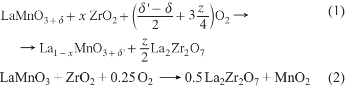
In several early works, it is reported that the total (oxygen-ionic) conductivity of La2Zr2O7 is about 2.0 × 10⁻⁴ S cm–1 at 1000 °C,75 3.8 × 10⁻⁵ S cm–1 at 1000 °C,76 and 4.2 × 10⁻⁴ S cm–1 at 800 °C;77 these values being by 50 – 400 times lower than those of YSZ electrolytes. According to the same reports, the ionic conductivity of SrZrO3 is by ~ 200 – 500 times lower than that of YSZ; however, no clear experimental data have been presented.
A thorough analysis of the literature data allows the determination of the ionic conductivity boundaries of both LZ and SZ over a wide temperature range (Fig. 2a,b).77 – 84 As can be seen, their conductivity varies considerably, which can be explained by the different densities of ceramics and the uncontrolled impurities introduced during the preparation of the powders and ceramics. Nevertheless, the conductivity values are obviously lower than those of zirconia-based ceramics. This is one of the main reasons, why the formation of such impurity phases is undesirable during the SOFC/SOEC operation. In more detail, the appearance of LZ and SZ phases at TPB and interface regions will not only cause a considerable increase in ohmic resistance due to hindering oxygen transport, but also in polarization resistance, since the latter is a sign of the processes of oxygen reduction reaction (ORR) or oxygen evolution reaction and also depends on the activity of oxygen ions at TPB/interface.
![[{"id":"hMC6iIrD1T","type":"paragraph","data":{"text":"Transport properties of La<sub>2</sub>Zr<sub>2</sub>O<sub>7</sub> and SrZrO<sub>3</sub> impurity phases and their effect on the performance of solid oxide electrochemical cells: (<i>a</i>) ionic conductivity of pure (non-doped) La<sub>2</sub>Zr<sub>2</sub>O<sub>7</sub>, 1 — Ref. 79, 2 — Ref. 80, 3 — Ref. 77, 4 — Ref. 81, 5 — Ref. 78; (<i>b</i>) ionic conductivity of pure (non-doped) SrZrO<sub>3</sub>, 1 — Ref. 82, 2 — Ref. 83, 3 — Ref. 84. Here, symbol * indicates the conductivity of YSZ according to Ref. 78; (<i>c</i>) volt-ampere and power density characteristics of a modeling SOFC depending on the LZ reaction layer thickness (h); (<i>d</i>) maximum power density and ohmic resistance characteristics of a modeling SOFC depending on the LZ reaction layer thickness (h)."}}]](/storage/images/resized/9A8OBS7gDTdsb70WDB9dQxgRmcGRTUE72irkg8pK_xl.webp)
Considering the possible effects of a LZ or SZ reaction layer on the electrochemical parameters (ohmic-type resistance and SOFC performance), a simplified model can be developed, (Fig. 2c). Taking into account specific starting (model) parameters, it can be seen that the formation of a continuous and dense insulating phase on the electrolyte/electrode can considerably deteriorate the SOFC performance (by several times) due to a substantial increase in the ohmic-type resistance, even if the polarization resistance remains the same. It should be reminded that, according to the kinetic computation, a 1 μm-thick LZ phase can be formed during 50 – 80 kh of long-term SOFC operation if the electrolyte/electrode interface is not adjusted. Actually, the degradation processes may be deeper due to the effect of other factors, including current/power supply (for example, see Fig. 1 g or Refs 85, 86), electrode coarsening,87 – 90 cation surface segregation,91 – 94 or poisoning.95 – 98 These are outside the scope of this review and wil not be discussed in detail.
Along with the transport properties of the LZ and SZ materials, there are other issues that can lead to possible degradation of the electrolyte/electrode interface and the electrochemical performance of SOFCs or SOECs. One of them is a thermomechanical feature of newly formed zirconate phases.
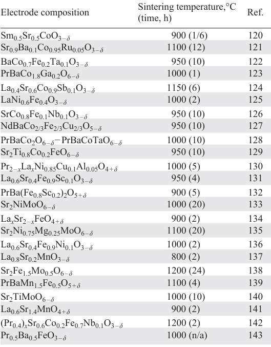
It is well known that the TEC values of zirconia electrolytes and LSM electrodes are in the ranges of (9.5 – 11.0) × 10–6 K–1 (see Refs 99, 100) and (10 – 13) × 10–6 K–1 (see Refs 100, 101), respectively. At the same time, these values vary slightly over a wide temperature range of 25 – 1200 °C. On the contrary, the LZ and SZ phases differ from YSZ and LSM in terms of their TECs (Fig. 3a,b).102 – 107 For example, LZ with a pyrochlore-type structure has lower and temperature-dependent TECs ranging from 7 × 10⁻⁶ to 8 × 10⁻⁶ K–1 at low temperatures (up to 300 °C) and from 8 × 10⁻⁶ to 9 × 10⁻⁶ K–1 at higher ones (see Fig. 3a). The TEC values of SZ with a perovskite-type structure are a function of temperature as well; however, the magnitude of TEC variation is higher (from 8 × 10⁻⁶ to 11 × 10–6 K–1 within 20 – 1200 °C) due to a series of phase transitions associated with a change in the symmetry of the perovskite structure (see Fig. 3b). The YSZ/LSM interface can be subject to failure,108 including the appearance of cracks, pores or the delamination of layers (Fig. 3c), as a result of the thermomechanical stress caused by the appearance of these new phases. The loss of both good adhesion and strong interlayer contact redound to a catastrophic increase in the contribution to the ohmic resistances and irreversible degradation of electrochemical devices.
![[{"id":"OaztyLO5zQ","type":"paragraph","data":{"text":"Thermal expansion behavior of YSZ, La<sub>2</sub>Zr<sub>2</sub>O<sub>7</sub> , and SrZrO<sub>3</sub> materials: (<i>a</i>) temperature dependences of thermal expansion coefficients, 1 — Ref. 102, 2 — Ref. 103, 3 — Ref. 104, 4 — Ref. 105, 5 — Ref. 107; (<i>b</i>) Temperature dependence of molar volume for SrZrO<sub>3</sub> . Reproduced from Ref. 103, Copyright The Ceramic Society of Japan, 2017; (<i>c</i>) The YSZ/LSM interface after electrochemical operation. Reproduced from Ref. 108, Copyright Spring er Science + Business Media, LLC, Inc., 2011."}}]](/storage/images/resized/Y8mfoD4w6FIwiwSIBKUopIVkSxhGGfvb4AhdS9P3_xl.webp)
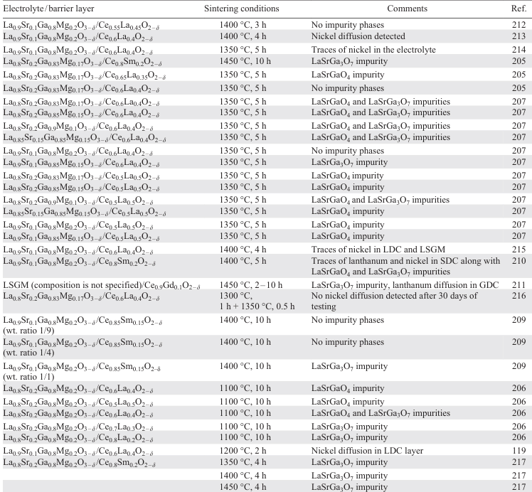
In addition to the mentioned detrimental effects of impurity phases, the loss of mechanical and electrical contact between YSZ and LSM layers can occur due to their TEC mismatch, as shown in numerous reports; Fig. 4 represents the experimental results of some of these reports.109 – 111
![[{"id":"r2-RfLP6qy","type":"paragraph","data":{"text":"Defects at the YSZ/LSM interface during SOFC or SOEC operation: (<i>a</i>) before and after anodic polarization at 0.5 A cm<sup>–2</sup> at 800 °C for 48 h. Reproduced from Ref. 109, Copyright Elsevier Ltd., 2011; (<i>b</i>) after electrolysis operation at 1.5 A cm<sup>–2</sup> at 800 °C for ~ 300 h. Reproduced from Ref. 110, Copyright Elsevier B.V., 2013; (<i>c</i>) before and after SOEC operation. Reproduced from Ref. 111, Copyright Elsevier B.V., 2015."}}]](/storage/images/resized/DlMdAvg4YLlcTBoo9iCp5m1yrgvbyr1P1TWoxE00_xl.webp)
2.4. Problems of chemical incompatibility with LaGaO3-based electrolytes
Materials based on lanthanum gallate (LaGaO3) co-doped with strontium and magnesium, i.e., (La,Sr)(Ga,Mg)O3 or La1 – xSrxGa1 – yMgyO3 – δ (labeled as LSGM), belong to a class of highly oxygen-conducting solid-state electrolytes.112, 113 The oxygen-ionic conductivity of LSGM is comparable to that of ceria-based electrolytes. However, unlike doped CeO2 , LSGM is an oxygen-ionic conductor over a wide oxygen partial pressure range and does not exhibit meaningful p- and n-type electronic conductivities under real experimental conditions. This allows the LSGM materials to be considered as promising electrolyte materials for solid oxide electrochemical devices, power generation, gas conversion, and etc. Contrary to the most solid-state oxide electrolytes, LSGM could be used as a supporting layer in electrochemical cells (so-called symmetric cells, Refs 114, 115) as well as a thin film electrolyte in combination with a conventional supporting nickel-ceramic anode.
One of the first papers demonstrating the application of LSGM in a SOFC with a nickel-based anode was published by Feng et al. in 1996.116 In this study, two different composite anodes, Ni – CeO2 and Ni–LSGM, were investigated in contact with a LSGM electrolyte. The sintering temperature of both anodes was 1130 °C. No barrier layers were introduced between the anode and the LSGM electrolyte. When investigating cells with Ni – CeO2 anode, a high anode overpotential, several times higher than that of the (La,Sr)CoO3 cathode, was detected. In studies of the cell with Ni–LSGM anode, the authors found a poor performance and a high degradation rate of SOFC output performance.
Later, it has been found that nickel oxide can interact with LSGM electrolytes at reduced temperatures (1125 °C) to form a LaNiO3 phase.117 In a fuel gas atmosphere (in particular, hydrogen), LaNiO3 is transformed into La2O3 and nickel. This leads to the formation of defects at the Ni-based anode/LSGM interface, a reason for blocking the ionic transport by La2O3 particles. This effect occurs because La2O3 is a stoichiometric oxide with no structural or defect disordering. Nickel has also been found to diffuse into the electrolyte, when the LSGM electrolyte is co-sintered with the supporting Ni-based anode at high temperatures.118 This diffusion into the LSGM bulk is estimated to be around 5 μm depth at 1350 °C. No nickel diffusion has been detected at 1250 °C (Fig. 5a). However, the latter investigations have shown that the nickel diffusion into LSGM can also occur at even lower temperatures (Fig. 5b, Ref. 119). Therefore, it is evident that the use of interlayers in SOFCs is necessary for the effective application of Ni-based anodes in contact with the LSGM electrolyte.
![[{"id":"Lu17NEvj4G","type":"paragraph","data":{"text":"Chemical compatibility issues of La<sub>1 – x</sub>Sr<sub>x</sub>Ga<sub>1 – y</sub>Mg<sub>y</sub>O<sub>3 – δ</sub> electrolytes: (<i>a</i>) SEM image of LSGM/Ni-SDC cell cross-section and nickel distribution profile for electrode sintering at 1250 and 1350 °C. Reproduced from Ref. 118, Copyright Elsevier Science S.A., 1999; (<i>b</i>) sketch of nickel diffusion from anode in LSGM electrolyte reproduced on the basis of elemental analysis. Reproduced from Ref. 119, Copyright Elsevier Ltd, 2020; (<i>c</i>) comparison of total conductivities of La<sub>1 – x</sub>Sr<sub>x</sub>Ga<sub>3</sub>O<sub>7 ± δ</sub> (Ref. 150) and La<sub>0.8</sub>Sr<sub>0.2</sub>Ga<sub>0.8</sub>Mg<sub>0.2</sub>O<sub>3 – δ</sub> (Ref. 151) materials."}}]](/storage/images/resized/o0lPCEJagOCRoAhVFna5HWoUneO0vh1gvcSyJJfG_xl.webp)
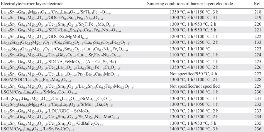
The compatibility of the LSGM electrolyte with conventional oxygen electrode materials based on manganites, cobaltites, and nickelites depends mainly on the sintering temperature of the electrode. The compatibility of the LSGM electrolyte with many different electrode materials has been demonstrated in a number of publications (Table 1, Refs 120 – 143). As can be seen, at reduced temperatures (typically below 1150 °C), LSGM is compatible with most modern oxygen electrodes, including highly active double cobaltite based ones. At high temperatures, the LSGM electrolyte actively interacts with the oxygen electrodes. In particular, LSGM is shown to interact with the La0.65Sr0.3MnO3 – δ , La0.7Sr0.3CoO3 – δ , La0.65Sr0.3FeO3 – δ , La0.65Sr0.3NiO3 – δ , and La0.6Sr0.4Co0.2Fe0.8O3 – δ at 1300°С.144 There are also a few studies showing the interaction of LSGM with electrodes at reduced temperatures, e.g. with GdBaCo2O5 + δ at temperatures above 900 °C,145 with Nd2NiO4 + δ at 1000 °C for 5 h,146 with Pr2 – xCaxNiO4 + δ at 900 °C for 10 h (x = 0, 0.5)147 and at 1200 °C for 1 h (x = 0, 0.3).148
In general, the incompatibility of LSGM with electrodes at high temperatures is not due to the chemical interaction between the electrolyte and the electrodes, but to diffusion reasons, usually lanthanum diffusion. This results in the formation of various magnesium-free phases, such as Sr3La4O9 , SrLaGa3O7 , and SrLaGaO4 .113 The formation of such phases can also be caused by gallium evaporation during the manufacture of dense or gas-tight electrolytes.149 The magnesium-free phases mentioned above are oxygen stoichiometric, which means that they have low oxygen-ionic conductivities. For example, the conductivity of SrLaGa3O7 is about seven orders of magnitude lower than that of LSGM (Fig. 5c, Ref. 150). The appearance of such phases leads to a dramatic increase in the resistance of the electrode/electrolyte interface, which degrades the performance of solid oxide electrochemical cells. It should be noted that there are several non-stoichiometric magnesium-free phases with conductivity lower than or equal to that of LSGM, such as La1.54Sr0.46Ga3O7.27 (Fig. 5с, Ref. 151). In summary, when using nickel-ceramic anodes with LSGM electrolyte, it is necessary to apply interlayers similar to those proposed for the ZrO2-based electrolytes. In the case of electrode materials sintered at low sintering temperatures, the use of interlayers is not necessary.
3. CeO2-based interlayers
3.1. Short details on ceria materials
Ceria (CeO2) doped with various acceptor dopants belongs to the oxygen-conducting fluorite-type materials, whose conductivity at 600 – 900 °C exceeds that of the zirconia-based electrolytes at least by ~1 order of magnitude (Fig. 6a).152 – 154 This property potentially allows the application of CeO2-based oxides as electrolytes for low- and intermediate-temperature SOFCs.155 – 157 However, the electrochemical cells with such an electrolyte suffer from internal short-circuit effects due to the easy Ce4+-to-Ce3+ transition in the fuel environment.158, 159 The latter reduces the efficiency of SOFCs at elevated temperatures and prohibits the use of ceria electrolytes for SOECs. Various material science and technological approaches have been used to mitigate the undesirable electronic leakage through the ceria electrolytes. Nevertheless, these approaches are effective for lab-scale cells and have not yet found real application in large-scale or commercial prototypes.
![[{"id":"GP6jfCU3OD","type":"paragraph","data":{"text":"General data on CeO<sub>2</sub>-based materials: (<i>a</i>) comparison of different oxygen-conducting electrolytes in terms of their ionic conductivity. Adapted from Ref. 152, Copyright The Royal Society of Chemistry, 2008; (<i>b</i>) thermal expansion behavior of Ce<sub>0.8</sub>Ln<sub>0.2</sub>O<sub>2 – δ</sub> ceramics. Reproduced from Ref. 161, Copyright Elsevier Ltd., 2011; (<i>c</i>) scopus analysis of the application of ceria functional layers in SOFCs/SOECs (accessed on July 20, 2023)."}}]](/storage/images/resized/NBtfFQj6ap7jJd5xjJxbqfKFmWHjHuSwh3jnxpL4_xl.webp)
Despite of the aforementioned drawbacks, the CeO2-based materials can be used as effective functional layers for SOFCs and SOECs due to their higher chemical compatibility (compared to zirconia-based electrolytes) with almost all potential electrode materials used, see Section 2.2. This can be explained by the fact that large Ce4+ cations exhibit a less acidic character compared to Zr4+ cations, implying a higher chemical compatibility of Ce-based oxides with phases containing basic cations such as Ca2+, Sr2+, Ba2+, and large lanthanides.160 In addition, doped CeO2 materials, exhibiting average TECs of (10 – 14) × 10–6 K–1 (Fig. 6b, Refs 161 – 164), allow to rationally smooth out the TEC mismatch between YSZ and electrode (especially, non-manganite) materials. The latter usually exhibit TECs above 13 × 10–6 K–1; the readers are referred to recent review works to learn in detail about the thermal expansion behavior of various electrode materials.165 – 173
The following sections highlight the various aspects regarding to the application of CeO2-based functional layers for solid oxide electrochemical cells. Due to the different functionalities of such layers, they may be reffered to in the literature as interlayers, barrier layers, blocking layers, protective layers, or buffer layers; in the present work, all these terms are considered as synonyms. As can be seen from Fig. 6c, the CeO2-based layers are widely used in research & development of SOFC and SOEC technologies.
3.2. Early practice of using bi-layered electrolytes
The first studies elaborating a bi-layer electrolyte configuration for SOFC applications were published in the late 90s of the last century.174 – 177 In these works, doped ceria was used as the main operating electrolyte, while doped zirconia was used as an additional layer at the electrolyte/anode interface. The introduction of YSZ or ScSZ had been proposed to suppress the n-type electronic conductivity of CeO2-based electrolytes, occuring under reducing conditions, see Section 3.1. As a result, the additional functional layer could sufficiently improve SOFC performance, including starting values of open circuit voltages and even power density characteristics, by blocking the internal electron current through the electrolyte.178 However, this improvement was observed at quite low thicknesses of the blocking layer due to its lower ionic conductivity compared to that of doped CeO2 . Moreover, the bi-layer cells should be fabricated at as low temperatures as possible due to strong cations interdiffusion between ceria/zirconia pairs.179 In an attempt to overcome these problems, the latest research direction in the development of SOFCs with the CeO2-based electrolytes is to use other electron blocking layers.158, 159, 180, 181
3.3. Ceria protecting layers for zirconia-based electrochemical cells
Uchida et al.54, 56 were among the first to propose the use of a SDC buffer layer for electrochemical cells of LSC|SDC|YSZ|Pt. Such cells were prepared in different ways by varying the sintering temperatures of the formation of the SDC layer (400 and 1100 °C) and the LSC electrode (1050 and 1150 °C). The electrochemical characterization of these cells was performed in an oxygen pump mode, using pure oxygen and air as the gases supplied to the opposite electrode sides. The cell consisting of the SDC layer sintered at 400 °C had the highest overpotentials, reaching more than 200 mV at 800 °C with a current density of 0.5 A cm–2. On the contrary, the cell with SDC sintered at 1150 °C showed ~2 times lower overpotentials (at higher current densities), which was attributed to the improved chemical compatibility between YSZ and LSC. These results have been confirmed in a number of other similar works; for example, see reports.58, 68, 182, 183
Duan et al.66 evaluated the effect of the GDC interlayer on the electrochemical performance of SOFCs designed as Ni-YSZ|YSZ|BSCF. Here, a 15 μm-thick YSZ electrolyte was formed onto a NiO/YSZ substrate by the tape-casting method and co-firing at 1400 °C, while a 1 μm-thick GDC was coated onto the YSZ electrolyte followed by its sintering at different temperatures, 1100, 1200, 1300, and 1400 °C for 1 h. The different sintering temperatures of the GDC layer were not chosen by chance. The authors sought to test a possible interaction between GDC and YSZ. According to the XRD analysis, the cationic cross diffusion was observed even at 1200 °C, although the main phases remained free of any impurities. However, the higher temperatures were more dramatic due to the complete dissolution of the GDC phase in the YSZ layer followed by the formation of (Zr,Ce)O2 solid solutions. The latter was suggested to be undesirable due to its lower ionic conductivity compared to those of GDC and even YSZ. The verification of this assumption was carried out in the SOFC performance analysis. More precisely, the cell without buffer layer showed a maximum power density of 440 mW cm–2 at 800 °C; the SOFC performance was as high as 830, 1150, 1450, and 1360 mW cm–2, when the GDC layer was sintered at 1100, 1200, 1300, and 1400 °C, respectively. Several conclusions can be drawn from these experimental results. First, the formation of impurity phases at the YSZ/BSCF interface is more severe than the potential reactivity of YSZ and GDC, at least for short-term SOFC testing. Second, the SOFC performance was found to decrease at very high sintering temperature of GDC, 1400 °C. However, full reactivity of YSZ and GDC was observed under these conditions. Therefore, the authors proposed an optimal sintering temperature of 1250 °C.
More recently, Kim et al.184 have provided a comprehensive analysis of SOFC performance, using the same reference system, Ni-YSZ|YSZ (20 μm)|BSCF. When such a cell was fabricated without a buffer layer, a maximum power density of 810 mW m–2 was achieved at 800 °C for 2 h of operation; however, this parameter decreased down to 630 mW cm–2 after the next 50 h. The dramatic performance deterioration was attributed to strong incompatibility of functional materials, since the calcined YSZ and BSCF mixture completely decomposed during their joint calcination at 800 °C for 50 h: different impurity phases (such as pure zirconia, strontium zirconate, and barium zirconate) were formed. The optimized SOFC design with a 1 μm-thick GDC layer showed a high power density of 1.2 W cm–2 at 800 °C, confirming that the formation of impurity phases can be efficiently eliminated by the dense GDC interlayer.
It should be noted that the recently discussed work of Duan et al.66 raised an important issue in terms of the microstructural quality of the ceria interlayers used and its effect on the chemical compatibility, although no detailed links between these properties were presented. More recently, in 2010, Lu et al.185 analyzed the electrochemical parameters of SOFCs, Ni-YSZ|YSZ (8 μm)|SDC (3 μm)|LSCF|LSC (where LSCF = La1 – xSrxCo1 – yFeyO3 – δ), depending on the porosity of SDC. To achieve this goal, the authors used two techniques to prepare the desired thin films: screen printing for the porous state and laser deposition for the dense state (Fig. 7a). It was established that the microstructural state of SDC affects the SOFC performance at all other parameters being equal. In more detail, the maximum power densities increased considerably when the dense SDC was used instead of the porous one: 400 vs. 260 mW cm–2 at 600 °C and 1200 vs. 680 mW cm–2 at 700 °C. This improvement was mainly attributed to the decreased ohmic-type component of resistance, while the polarization resistances were virtually the same, except very low testing temperatures. The result of this work allows a very important conclusion to be drawn: porous interlayers generate high ohmic losses due to the absence of continuous contact at the zirconia/ceria interface. This has been confirmed in more recent studies for different SOFC designs.186 – 190
![[{"id":"l8mHyDlBGI","type":"paragraph","data":{"text":"Ceria interlayers and their effects on the properties of SOFCs and SOECs: (<i>a</i>) cross-sections of two SOFCs with screen-printed SDC (the left photo) and laser-deposited SDC (the right photo) and their electrochemical parameters. Reproduced from Ref. 185, Copyright Elsevier B.V., 2009; (<i>b</i>) cross-sections and element distribution maps for two SOECs tested at 1.3 V and 750 °C for 50 h depending on the state of the GDC layer. Reproduced from Ref. 192, Copyright Elsevier B.V., 2021; (<i>c</i>) microstructure and element distribution maps in poly- and single crystalline GDC layer after 300 h of operation for the LSCF|GDC|YSZ|Pt cell under open circuit voltage mode. Reproduced from Ref. 197, Copyright The Electrochemical Society, 2018; (<i>d</i>) experimental setup for the verification of Sr-containing gas phase diffusion and experimental data for the YSZ surface threated at 1000 °C for 200 h. Reproduced from Ref. 198, Copyright The American Ceramic Society, 2018."}}]](/storage/images/resized/3IZC5gIpdYHkRvzXaY2IwKosW4LsyogVOuQfvODg_xl.webp)
Another issue is that the porous ceria interlayers have a low ability to inhibit cations interdiffusion between functional layers.191, 192 As a result, low conductive impurity phases often form at the corresponding interface (Fig. 7b). This undesirable effect is due to two independent chemical features.
First, the diffusion of various cations (including Sr2+ from Sr-containing electrodes and Zr4+ from zirconia electrolytes) along the grain boundaries of the CeO2-based materials is by several orders of magnitude faster than that through the bulk (grains).193 – 196 As a result, SrZrO3 can form in interlayers with a high grain boundary density, either at the interfaces or even in the bulk region, as clearly shown in Fig. 7c.197 On the other hand, the dense interlayers with reduced or free grain boundaries show no evidence of SrZrO3 formation.
Second, strontium diffusion through a gas phase is possible even when there is no direct contact between zirconia-based electrolytes and strontium-containing electrodes.198 – 202 This process is proposed to be observed under humid atmospheres, in which the formation of a highly volatile Sr(OH)2 compound takes place followed by its diffusion from the electrode to the interlayer/electrolyte interface via a gas phase in the interlayer pores and channels or along the grain boundaries of the interlayer (Fig. 7d ).
3.4. Ceria protecting layers for gallate-based electrochemical cells
As shown in Section 2.4, the presence of a barrier layer is necessary when using nickel-ceramic anodes in contact with LSGM-based electrolytes. The application of zirconia-based barrier layers has proven to be ineffective in improving the compatibility of nickel-ceramic anodes with LSGM. For example, when using a ScSZ barrier layer between the supporting nickel cermet and the LSGM electrolyte, the formation of the LZ phase in the buffer layer has been detected at a sintering temperature of 1450 °C as a product of the interaction between ScSZ and LSGM. This results in a tremendous increase in the ohmic resistance of the cell (Fig. 8a, Ref. 203).
![[{"id":"ypIEbx353v","type":"paragraph","data":{"text":"Chemical, microstructural and electrochemical features of LSGM-based SOFCs: (<i>a</i>) SEM image of cross-section LSGM/NiO – GDC and LSGM/ScSZ/NiO – GDC anode supported cells and ohmic resistance of these cells with and without ScSZ barrier layer. Reproduced from Ref. 203, Copyright Elsevier B.V., 2006; (<i>b</i>) temperature dependencies of total conductivity of Ce<sub>0.8</sub>Ln<sub>0.2</sub>O<sub>2 – δ</sub> used as buffer layers (Ln = La, Sm, Gd). Reproduced from Ref. 164, Copyright Elsevier B.V., 2008; (<i>с</i>) sketch of the extension of the electrode reaction area onto the surface of the barrier layer. Reproduced from Ref. 204, Copyright Elsevier B.V., 2022; (<i>d</i>) BSE image and the corresponding EDS line map across the AB direction on the cross-section of LSGM/LDC/Ni-GDC after stability test at 650 °C for 400 h. Reproduced from Ref. 208, Copyright Elsevier Ltd., 2018; (<i>e</i>) voltage and power density vs. current density for cells with and without barrier layer. Reproduced from Ref. 210, Copyright Elsevier B.V., 2012; (<i>f</i>) profiles of La-concentration across the GDC buffer layer which was co-fired at 1450 °C with different duration time and cross section of the NiO – GDC/GDC/LSGM cell. Reproduced from Ref. 211, Copyright Springer Science+Business Media, LLC, 2007."}}]](/storage/images/resized/JqMn4Sjvet3EejU3rV4yvYoKGDbOYIOp47EPOyjS_xl.webp)
Typically, interlayers based on ceria doped with lanthanum or samarium, or gadolinium are used to prevent interaction and diffusion at the nickel/LSGM interface. In addition, the doped ceria-based interlayers contribute in increasing the SOFC performance by reducing the polarization resistance of cermet electrodes. This is due to the fact that the complex oxides of CeO2 – La2O3 (LDC), CeO2 – Sm2O3 (SDC), and CeO2 – Gd2O3 (GDC) partially lose oxygen in reducing atmospheres and become mixed ionic-electronic conductors. Pikalova et al.164 have shown that the conductivity of these oxides in a wet hydrogen atmosphere is about one order of magnitude higher than that in air (Fig. 8b). The appearance of mixed conductivity results in the expansion of the electrochemical reaction zone from TPB to the surface of the protective layer (Fig. 8c, Ref. 204); this is a reason for the observed improvements in the electrode performance. As shown in Fig. 8b, the nature of the dopant cation has a weak effect on the conductivity of doped ceria in both oxidizing and reducing atmospheres. Therefore, given the small thickness of the barrier layer, from the point of view of unfavorable increasing the ohmic resistance of the electrochemical cell, it makes no difference which cation dopant for ceria is used in the barrier layer. However, there are significant differences in the choice of dopant cation for the barrier layer in terms of preventing the processes of interaction and diffusion.
As shown by Huang et al.,205 lanthanum, as part of the LSGM phase, exhibited high mobility and diffusion rates. For this reason, and due to the lanthanum chemical gradient, the SDC barrier layer proved to be ineffective. On the contrary, the LDC barrier layer (Ce0.6La0.4O2 – δ) demonstrated its high efficiency, primarily by virtue of the reduced lanthanum chemical gradient between LSGM and LDC. These results were later refuted by Eba et al.206 A mixture of LSGM and LDC (1/1 wt/wt) was calcined at 1100 °C for 10 h. After this treatment, LaSrGa3O7 and LaSrGaO4 impurity phases were detected in the mixture. More detailed studies on the compatibility of the LSGM electrolyte and LDC were carried out by Kumar et al.207 They found that the formation of impurity phases was mainly dependent on the ratio of cations in both LSGM and LDC. Only for one mixture composed of La0.9Sr0.1Ga0.8Mg0.2O3 – δ and Ce0.6La0.4O2 – δ impurity phases were not detected. According to the results of Wang et al.,208 no impurity phases were detected in the LSGM/LDC mixture after its calcination at 1400 °C for 10 h. In addition, no diffusion of nickel from the anode into the LDC barrier layer was found after 400 h operation of a SOFC at 650 °C (Fig. 8d ).
Xu et al.209 confirmed that the formation of impurity phases in the SDC/LSGM mixture depends on the ratio of the components. After annealing at 1400 °C for 10 h, no impurity phases were detected in the SDC/LSGM mixture with SDC fraction of 80 and 90 wt.%. The formation of the LaSrGa3O7 phase was revealed at a SDC fraction of 55 wt.%. Similarly, the behavior of the LSGM electrolyte in contact with the SDC barrier layer was investigated by Morales et al.210 They observed the formation of LaSrGa3O7 and LaSrGaO4 phases at a calcination temperature of 1400 °C for 5 h. Despite this fact, the SOFC with the SDC interlayer demonstrated power density values twice as high as those of a similar cell without SDC (Fig. 8e). The diffusion of lanthanum through the GDC interlayer was shown by Lee et al.211 The authors found that the depth of the diffusion layer increased with time. At 1450 °C, lanthanum diffused through almost the entire barrier layer in ~10 h (Fig. 8f). The authors also observed cracking at the LSGM/GDC interface, which can be explained by the TEC mismatch between the origin and impurity phases (see Fig. 8f ).
Table 2 summarizes the compatibility of LSGM electrolytes and ceria-doped oxides. As can be seen, the results are often ambiguous and even contradictory. It can definitely be stated that all ceria-based barrier layers are effective in preventing the interaction of the nickel-ceramic anode with the LSGM electrolyte. Most researchers are inclined to believe that the most promising composition from the viewpoint of preventing the lanthanum diffusion is Ce0.6La0.4O2 – δ . Moreover, the effectiveness of the barrier layer towards forming the impurity phases seems to depend on the concentration of all cations in the LSGM and doped ceria.
As shown in Section 2.4, the LSGM derived electrolytes have good compatibility with the most complex oxide electrode materials at reduced sintering temperatures. However, in some cases, LSGM can interact with electrode materials, even at low temperatures. For example dos Santos-Gómez et al.138 have reported that LSGM can react with Sr2NiMoO6 – δ even at 1000 °C to form LaSrGaO4 and LaSrGa3O7 phases. Therefore, in some cases, especially if electrodes contain nickel, the use of barrier layers is necessary to achieve good chemical compatibility in the electrolyte/electrode pairs.
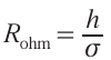
The process of manufacturing interlayers on the LSGM electrolytes is simpler than on the supporting cermet electrodes. The reason is that the interlayer is formed on a dense sintered LSGM electrolyte rather than on a porous nickel-ceramic support. In addition, the sintered protective layer does not require electrolyte coating and sintering at high temperatures, reducing the probability of cation diffusion from the contacting layers. Table 3 presents some selected data reagarding the fabricated electrochemical cells with the LSGM supported electrolytes and ceria-based barrier layers.
3.5. Ceria protecting layers for protonic ceramic electrochemical cells
Proton-conducting oxide materials (PCOMs) represent a promising class of electrolytes for various electrochemical applications, including SOFCs, SOECs, pumps, and sensors.237, 238 – 240 Their ionic conductivities are governed by the ability of oxygen vacancies to dissociatively absorb water, producing protons with a higher mobility compared to that of conventional oxygen vacancies as charge carriers for oxygen-conducting electrolytes. Due to this fact, acceptable ionic conductivity of PCOMs can be achieved at reduced temperatures (450 – 650 °C, Refs 241 – 243), resulting in very high performance of solid oxide electrochemical cells. Despite active research in this field, no large-scale PCOM-based SOFCs/SOECs have been fabricated and tested in long-term operation until now. Such limitations come from a number of unresolved problems related to various material science and technological aspects.244, 245 Among them, the rational selection of suitable electrode materials is a matter of continuous search and discussion.246 – 251
While the problems of thermomechanical compatibility of PCOM/electrode pairs have been thoroughly discussed in recent works,169, 249, 237, 239, 252 the chemical compatibility issue is a bottleneck, particularly due to the lack of long-term experiments mentioned above.
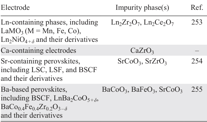
From a general perspective, cation interdiffusion could occur between proton-conducting materials and electrode systems at elevated temperatures. Table 4 lists possible phases that could potentially appear at the corresponding interface. Apart from the impurity phases formed by cross-diffusion of cations from different functional materials, CeO2 and ZrO2 impurity particles might precipitate at the electrolyte/electrode interface as a result of the barium chemical gradient between functional materials and its diffusion from the electrolyte to the electrode followed by partial dissolution in the perovskite structure.254, 256, 257 Finally, it should be mentioned that several works 255, 258 report the cations cross-diffusion between the Ba(Ce,Zr)O3/Ba(Co,Fe)O3 perovskite pairs without any formation of impurity phases. This is due to the high flexibility of the perovskite structures, which allows the dissolution of a certain portion of cations without any sign of decomposition. All these chemical compatibility problems can be partially eliminated by using reduced sintering temperatures (typically below 1100 °C) during the electrode preparation. However, the impurity phases listed in Table 4 can form even under long-term operation of electrochemical cells at reduced temperatures. Therefore, the utilization of CeO2-based barrier layers is a possible approach to improve the stability and integrity of the electrolyte/electrode interfaces as well.
The literature analysis provided shows that the CeO2 interlayer has only recently been used by the O’Hayre group.259 – 262 As shown in Fig. 9a, the insertion of a GDC layer between a BaCe0.4Zr0.4Y0.1Yb0.1O3 – δ electrolyte and a BaCo0.4Fe0.4Zr0.1Y0.1O3 – δ electrode has been found to improve the long-term stability of a developed protonic ceramic fuel cell (PCFC, this term is used for SOFCs composed of proton-conducting electrolytes) stack. In addition, the performance of such a stack has been also significantly improved in terms of reducing the polarization resistances (Fig. 9b). This is presumably due to the mitigation of the deleterious accumulation of excess charged adsorbate species on the active electrode surface during electrode polarization, although the root cause of this degradation mechanism remains an active area of investigation.
![[{"id":"ZWXZOhTIRF","type":"paragraph","data":{"text":"Effect of the CeO<sub>2</sub>-based interlayer on the performance of protonic ceramic stacks: (<i>a</i>) long-term stability and degradation rates of protonic ceramic fuel cell stack depending on temperature and type of fuel; (<i>b</i>) distribution of relaxation time functions (γ · ln τ) depending on operating times, voltage used, and absence/presence of GDC interlayer. These panels were reproduced from Ref. 261, Copyright Elsevier B.V., 2022."}}]](/storage/images/resized/IXf81kax8v88ChJPNFlrxWPKQoZP9N30LDPSRxJG_xl.webp)
3.6. Limitations of CeO2-based protecting layers
The use of doped ceria interlayers for electrochemical cells based on oxygen-ionic or proton-conducting electrolytes is an efficient approach to suppress possible interactions between different functional materials. As shown in Section 3.3, such interlayers are suggested to be designed in a dense form, which enables the fast ionic exchange across the electrolyte/interlayer interface due to its good adhesion, extended electrochemically active sites, and lower probability of impurity phase formation. However, the densification of ceria materials is a matter of active research.263 – 267 In more detail, the conventional sintering temperatures above 1400 °C are required to produce dense bulk ceria materials. However, such high temperatures are not suitable for the fabrication of multilayer electrochemical cells because of the high affinity of the ZrO2 and CeO2 fluorite phases and, correspondingly, possible dissolution of guest ions in their own structures (i.e., zirconium in ceria and cerium in zirconia). The cationic stoichiometry deviations of strictly designed electrolyte and interlayer compositions result in a dramatic decrease of their oxygen-ionic conductivity; more importantly, this effect can be equivalent to the formation of insulating impurity phases. In this regard, the lowest possible sintering temperatures are required to produce the interlayers free of defects and grain boundaries.
Tsoga et al.268, 269 were among the first to conduct a comprehensive study of the interaction between YSZ and GDC phases and its effect on the electrochemical properties. The authors studied diffusion processes between zirconia and ceria materials in the pellet and thin film forms; the sintering was performed between 1200 and 1500 °C with different holding times. The experimental data obtained were analyzed by SEM+EDX analysis. It was found that the interdiffusion process in YSZ|GDC takes place already at 1200 °C; this process is accompanied by the formation of a reaction zone (whose ionic conductivity is by ~1 – 2 orders of magnitude lower than that of the parent phases, Fig. 10a, Refs 268 – 271) and the appearance of microstructural defects (pores) in the YSZ layer near its contact with GDC according to the Kirkendall effect. The appearance of pores was explained by a higher diffusion of Gd3+-ions in the YSZ phase than that of Ce4+-ions. However, no relationship between the thickness of the reaction layer and sintering conditions was observed.
![[{"id":"UGXTlrvlFo","type":"paragraph","data":{"text":" Interaction features between zirconia and ceria functional materials: (<i>a</i>) ionic conductivities of the Zr – Ce – Y – Gd reaction layer and YSZ and GDC phases. Reproduced from Ref. 268, Copyright Trans Tech Publications Ltd., 1999 and from Ref. 271, Copyright Elsevier B.V., 2019; (<i>b</i>) STEM + EDX analyses of the YSZ|GDC interface formed during sintering at 1300 °C for 2 h and subsequent calcination at 1100 °C for 2 h. Reproduced from Ref. 272 upon 4.0 CC BY-NC-ND license; (<i>c</i>) SIMS depth profiles of the 10GDC|8YSZ before (the left panel) and after (the right panel) pre-annealing at 1300 °C for 5 h. Reproduced from Ref. 273, Copyright Elsevier B.V., 2014. (<i>d</i>) Segmented SEM images of the GDC layer and its interfaces with the LSCF cathode and YSZ electrolyte depending on the GDC sintering temperature. Reproduced from Ref. 274, Copyright Elsevier B.V., 2017. ID is interdiffusion zone."}}]](/storage/images/resized/adfKBOx7GtuViXQhZElG1JIUIffvZkD1goFPQByw_xl.webp)
Chou et al.272 examined the chemistry of the YSZ|GDC interface by scanning transmission electron microscopy (STEM) and EDX spectroscopy. They found that the sintering of the GDC layer onto the YSZ electrolyte at 1300 °C for 2 h resulted in the appearance of a wide (~ 600 nm) reaction layer (Fig. 10b) as a result of intense cation cross-diffusion. It can be clearly seen that the gadolinium diffusion in YSZ is much higher than that of cerium diffusion, which is in agreement with the previous reports.
Wang et al.273 utilized secondary ion mass spectrometry (SIMS) to investigate the depth profiles of all cations existed in the GDC and YSZ phases. According to their results (Fig. 10c), a ~ 2.5 μm reaction layer was formed between the GDC layer formed onto a YSZ substrate and then sintered at 1300 °C for 5 h. Analysis of the depth profiles revealed that both cerium and gadolinium ions exhibited a limited interdiffusion in YSZ, while yttrium and, especially, zirconium diffusion profiles were deeper in GDC, probably due to its high defectness.
It is evident that the thickness of the reaction layer depends on sintering temperature and holding time. If the previous works report unclear relationships between these parameters, the study by Wankmüller et al.274 discovers more details. To provide precise phase analysis, the authors used a correlative tomography technique, which made it possible to obtain interesting results. As shown in Fig. 10d, the interdiffusion layer was formed even at 1100 °C and expanded in width with increasing sintering temperature; in addition, the SZ layer was also formed through the strontium diffusion from the LSCF electrode through the pores and grain boundaries of GDC. However, if the formation of the SZ phase can be inhibited by using denser interlayer structures (Section 3.3), it is technologically difficult to eliminate the interdiffusion layer. To address this issue, many physical- and chemical-assisted techniques have been used: atomic laser deposition,275 physical vapor deposition,276 pulsed vapor deposition,277 magnetron sputtering,278 radio frequency sputtering,279 spray pyrolysis,280 aerosol deposition,281 infiltration process,282 wet-etching and thin film deposition,283 chemical solution deposition and electrostatic spray deposition,284 electrodeposition,285 inkjet printing infiltration,286 infiltration of porous frameworks,188 precursor-driven facile densification,287 sintering additive-assisted densification,288 spin-coating,289 and etc. Despite this variety of techniques and many promising results related to the dense interlayer fabrication, considerable attention should be paid to simplicity, reliability, reproducibility, precursor/equipment/process cost, and scalability of the proposed techniques.
3.7. Variations in utilizing CeO2-based layer compositions
It is clear from the previous sections that the SDC and GDC interlayers have been widely used to solve chemical compatibility problems for various solid oxide electrochemical cells. However, other interlayer compositions can also be utilized successfully.
Somekawa et al.290 experimented with two compositions, YDC (Ce0.8Y0.2O2 – δ) and LDC (Ce0.8La0.2O2 – δ), along with the conventionally used one, GDC. From a chemical viewpoint, YDC and LDC are actually more convenient than GDC because of the more uniform chemical potential distribution profile of yttrium in a YSZ|YDC|LSM system or lanthanum in a LSM|LDC|YSZ(ScSZ) system. The authors prepared three samples, YSZ|GDC, YSZ|YDC, and YSZ|LDC and sintered them at 1500 °C for 10 h. Then, the SEM/EDX analyses were performed to find out the most promising interlayer composition. According to the experimental results, it was found that LDC is unsuitable for characterizing bi-layer pairs (without LSM) due to the strong lanthanum localization at the interface, which is a prerequisite for the formation of the low conductive LZ phase. Comparing the remaining pairs, the authors found that cerium diffusion in the YSZ electrolyte was lower in YSZ|YDC than in YSZ|GDC. In addition, two SOFCs with these interlayers were fabricated and tested at 800 °C; their results also showed that the lower ohmic voltage drops and overpotentials were achieved in the case of the YDC interlayer (122 and 73 mV against 168 and 129 mV for GDC, respectively). The next work of Somekawa et al.291 showed that the Ce0.8Y0.2O2 – δ composition was the most optimal of variants of the Ce1 – xYxO2 – δ system (0.05 ≤ x ≤ 0.25) in terms of the lowest diffusion of cerium into the YSZ electrolyte and the highest ionic conductivity.
Sumi et al.292 conducted a comprehensive research comparing GDC and LDC interlayers. The replacement of GDC by LDC composition was of a dual nature. On one side, the ionic conductivity of the sintered YSZ|LDC mixture was found to be higher than that of the YSZ|GDC mixture. On the other side, they exhibited the formation of La2Zr2O7 at the corresponding interface with much lower conductivity than that of Gd2Zr2O7 , which was also observed experimentally for the YSZ|GDC mixture. As a result, the power densities of single SOFCs with YSZ electrolyte and La0.6Sr0.4Co0.2Fe0.8O3 – δ electrode were comparable for both interlayers (250 ± 10 mW cm–2 at 600 °C and 700 ± 30 mW cm–2 at 700 °C).
Tb-doped CeO2 (Ce0.8Tb0.2O2 – δ , TDC) has been proposed as a mixed ionic electronic conductor (MIEC) in a buffer form for a YSZ|Nd2NiO4 + δ system.293 To confirm the advantageous function of the TDC, three YSZ|Nd2NiO4 + δ cells with Pt counter electrodes were prepared: without buffer layer, with GDC and with TDC. The polarization resistances of these cells at 850 °C were 2.63, 1.02, and 0.27 Ω cm2, respectively, confirming that the ORR process was dramatically improved due to the additional path of oxygen diffusion and exchange through the developed buffer layer. Unfortunately, no solid conclusion can be drawn regarding the terbium ions on the interfusion chemistry, since the buffer layer was prepared at the low sintering temperature (900 °C).
Flura et al.294 proposed another MIEC representative, Ce0.7Pr0.3O2 – δ (PDC), for electrochemical cells composed of 3YSZ and La2NiO4 + δ (LN). First of all, they compared symmetrical cells, Pt|3YSZ|Pt, without any interlayer, with the conventional GDC interlayer, and with PDC. The electrochemical impedance spectroscopy (EIS) analysis revealed that the overall resistances of these cells at 800 °C were 0.55, 0.40, and 0.32 Ω cm2, respectively, in good agreement with the results of the previously mentioned work. Then, the comparative analysis was carried out for LN|3YSZ|LN – based symmetrical cells, where the GDC and PDC interlayers were sintered at 1300 °C for 3 h. For these cells, the overall polarization resistance for the former case was also higher than that for the latter (0.88 vs. 0.64 Ω cm2 at 600 °C). In addition, the type of the interlayer affected the impedance spectra shape. While the GDC-based cell exhibited spectra that could be described by the pronounced Gerischer element, the PDC cell did not have such an element. A detailed analysis of the electrochemical data allowed the authors to conclude that the PDC interlayer is more suitable than the GDC. This can be explained by the fact that the pyrochlore based phases can be formed in all cases: Gd2Zr2O7 (GZ) in the case of the GDC interlayer and (Ce,Pr)2Zr2O7 (PZ) in the case of the PDC interlayer. However, due to the transition oxidation state behavior of praseodymium, the mixed ionic-electronic conductivity of PZ is considerably higher than that of GZ, which does not introduce any additional resistance to ohmic and electrode processes.
Recently, Wang et al.295 have proposed another Pr-containing barrier layer with a Ce0.8Pr0.1Gd0.1O2 – δ (PGDC) composition. There are several reasons, why co-doping could be better than GDC or PDC mono-doping. First, PGDC exhibits a higher ionic and electronic conductivity than GDC,296 – 298 which contributes to better performance towards ORR. Second, the high concentration of praseodymium in ceria leads to the appearance of undesirable chemical expansion effects at temperatures above 400 – 600 °C.299 – 302 Therefore, tailoring the appropriate Pr-content is a rational way to design promising barrier layers. The authors fabricated two single SOFCs with a design of Ni-YSZ|YSZ|A|LSCF-A, where the composition A (A = GDC or PGDC) was used as both barrier layer and electrode part. In turn, the barrier layer was fabricated by screen-printing followed by sintering at 1200 °C for 2 h. It was confirmed that the maximal power density was higher for the PGDC layer (690 vs. 500 mW cm–2 at 750 °C) due to a decrease in the polarization resistance (0.300 vs. 0.368 Ω cm2 at the same temperature). The better performance of the PGDC derivative, Ce0.8Pr0.1Sm0.1O2 – δ , was experimentally confirmed not only for the YSZ-based electrochemical cells, but also for SDC-based ones.303
Yang et al.304 evaluated the functions of a new buffer layer, Ce0.85Sm0.075Nd0.075O2 – δ (SMDC), compared to the conventional ones (GDC and SDC), when characterizing single SOFCs with a symmetrical configuration of PSF|BL|YSZ|BL|PSF, where PSF = Pr0.6Sr0.4FeO3 – δ , BL = buffer layer. Here, one of three BL was formed onto the YSZ electrolyte (before the electrode formation) by spin-coating method. First, the symmetrical cells were characterized in non-separated gas spaces, when both electrodes are in contact with the same atmosphere (air or hydrogen). The SMDC-based cell had the best electrochemical performance in air: the overall polarization resistances were 1.45, 0.46, and 0.19 Ω cm2 at 700, 750, and 800 °C, respectively; these were lower compared to the GDC-based cell (2.73, 0.62, and 0.27 Ω cm2) and the SDC-based cell (2.57, 0.57, 0.21 Ω cm2), respectively. The electrochemical performance of the SMDC-based cell in hydrogen was slightly inferior to that of the SDC-based cell: 1.11 vs. 1.00 Ω cm2 at 700 °C and 0.34 vs. 0.33 Ω cm2 at 800 °C. When the same cells where characterised in the gas-separated space mode (i.e., in the fuel cell mode), the highest maximum power densities were also achieved for the SMDC-based cells: 72, 132, 212, and 318 mW cm–2 at 650, 700, 750, and 800 °C, respectively. Although various electrochemical sets confirm the better performance of SMDC than GDC or SDC, no clear explanation for these results has been presented.
Wu et al.305 used two types of buffer layers (SDC and GDC) and provided an in-depth comparison of their electrochemical properties for symmetrical and single fuel cells. The EIS analysis of the symmetrical cells with a configuration of LSC – SDC|BL|YSZ|BL|LSC – SDC showed that the polarization resistances for BL = SDC were lower than those for BL = GDC: 0.27 vs. 0.48 Ω cm2 at 600 °C, 0.06 vs. 0.10 Ω cm2 at 700 °C, and 0.02 vs. 0.03 Ω cm2 at 800 °C. The electrochemical measurements carried out for the Ni-YSZ|YSZ|BL|LSC – SDC cells confirm the better performance for SDC: 280 vs. 230 mW cm–2 at 600 °C and 990 vs. 820 mW cm–2 at 700 °C. The authors explained these findings by a higher electronic conductivity of SDC (according to X-ray photoelectron spectroscopy, the molar concentration of Ce3+-ions in SDC was equal to ~35% against ~27% for GDC). This explanation seems to be speculative, since both SDC and GDC are purely oxygen-ionic conductors under oxidizing conditions.
Breakthrough results have recently been reported by Yu et al.306 The authors used an ultrathin (250 nm) SMDC interlayer in a solid oxide cell of Ni – ScSZ|ScSZ (3 μm)|SMDC|PBSCF-GDC, which was tested in both fuel cell and electrolysis cell modes (where PBSCF = PrBa0.5Sr0.5Co1.5Fe0.5O5 + δ). This layer was formed onto the ScSZ electrolyte by the spin-coating process from a special gelatin-based solution. The application of optimized technological approaches enabled the authors to obtain remarkable performance at 750 °C, including a maximum power density of 3.36 W cm–2 for the fuel cell mode and a current density of 2.1 A cm–2 under thermoneutral conditions for the electrolysis cell mode. The detailed EIS analysis showed that the gelatin-derived SNDC interlayer not only reduced the ohmic resistance by facilitating oxygen conduction in the bulk, but also reduced the electrode resistance by providing more active sites at the interlayer/electrode interface.
4. SOFCs and SOECs with ceria protecting layers
4.1. Achievements for zirconia-based cells
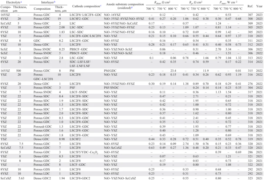
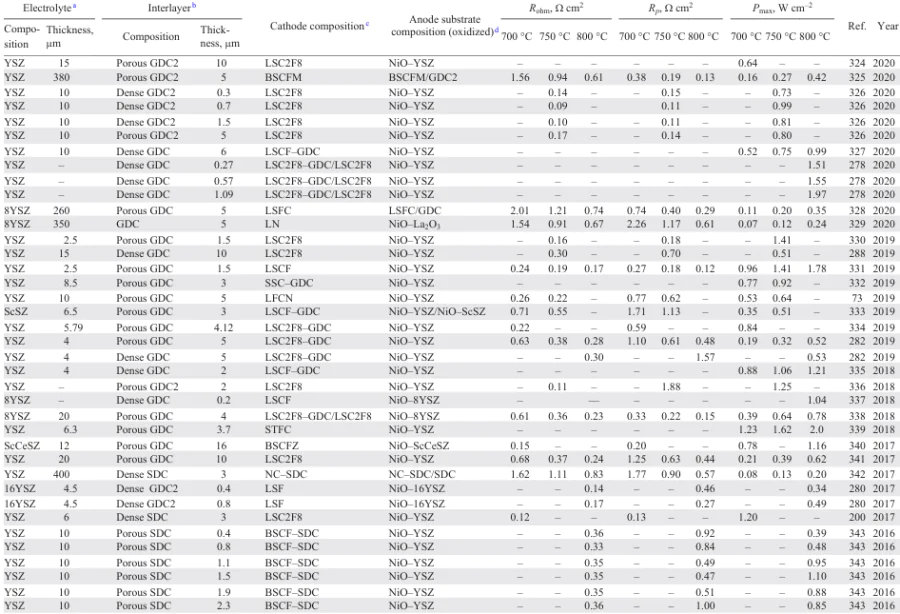
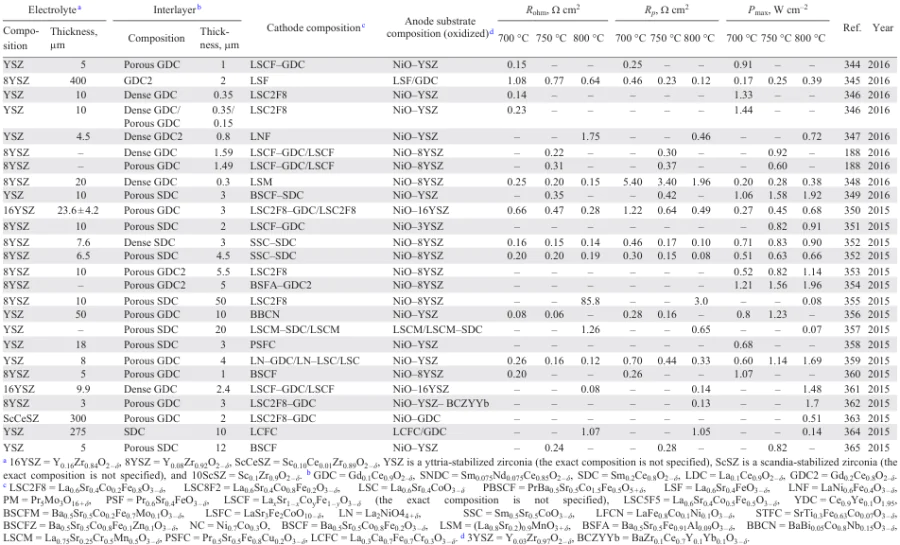
As shown in the previous sections, the chemical compatibility problems for various types of SOFCs and SOECs can be successfully eliminated by introducing CeO2-based thin films into multilayer structures. According to the analysis of literature data (see Fig. 6c), there are more than 460 research articles dealing with such a tactic; most of these studies are devoted to ZrO2-based SOFCs and SOECs. When examining the experimental data of specific studies, one can see many outstanding results in the performance of solid oxide electrochemical cells caused by a targeted adjustment of various (chemical, technological, experimental) factors. However, the number of such factors is so large that a comparative analysis becomes very difficult. Nevertheless, by considering a large set of experimental data, it is possible to reveal regularities linking some initial parameters with the output characteristics of such complicated objects as SOFCs and SOECs. To provide up-to-date information, we have analyzed recent experimental results on the use of the CeO2 interlayers in ZrO2-based SOFCs. These data (published within a period of 2015 – 2023) are presented in Table 5 and visualized by means of Fig. 11 and Fig. 12.
![[{"id":"ncHX8zEb8L","type":"paragraph","data":{"text":"Performance of SOFCs based on zirconia electrolytes and ceria interlayers depending on their thickness. Here, R<sub>ohm</sub> is the ohmic resistance, R<sub>p</sub> is the polarization resistance, P<sub>max</sub> is the maximum power density, h is the thickness of either electrolyte or interlayer, or both. The arrows show an approximate trend for clarity. The double logarithmic coordinates are also presented for clarity. These data were taken from Table 5."}}]](/storage/images/resized/dBlmtmWc2TtQX45Z2Fkn4g2U9d4z94nccejLWweU_xl.webp)
Table 5 shows that some individual SOFC representatives can exhibit very high power density values exceeding 1 W cm–2 at 700 °C and 2 W cm–2 at 800 °C. As mentioned above, this performance can be represented as a complex impact of numerous factors, including the compositional and microstructural differences of the anode, cathode, electrolyte, and interlayer materials. Since the latter (i.e., the ZrO2-based electrolytes and CeO2-based interlayers) are common to all the SOFCs considered, it is reasonable to examine their effects on the electrochemical parameters.
Fig. 11 represents various relationships between the thickness of thin films and some electrochemical parameters. First of all, it is interesting to analyze the behavior of the ohmic resistance (Fig. 11a) because of its close relationship with the thickness of the electrolyte:
where Rohm is the ohmic resistance, h is the thickness of the electrolyte, σ is the conductivity of the electrolyte.
Considering that the conductivity is constant for the same electrolyte composition and measurement conditions, the Rohm values should increase with increasing electrolyte thickness. According to Fig. 11a, such a trend is indeed observed (indicated by an arrow). However, it should be noted that the introduced CeO2-based films can also contribute to the ohmic component of resistance, especially for thick and porous interlayers. When plotting the Rohm = f (hinterlayer) dependencies, no regularities are observed (Fig. 11b): there is a low data density or a large scatter of the data. This comes from the fact that the Rohm values are almost completely regulated by the ohmic resistance of the electrolyte due to the thickness and conductivity differences between doped zirconia and ceria materials. It seems that the ohmic resistance of the interlayers is rather low (compared to that of zirconia), although the data density becomes narrow for a relationship of Rohm = f (helectrolyte + hinterlayer) (see Fig. 11) compared to that for Rohm = f (hinterlayer). The latter indicates that the ohmic resistance of the interlayer is not completely negligible.
Fig. 11d – f show the ohmic resistance contribution to the total SOFC resistance in the same manner as before. Again, for the above reasons, no clear relationships can be seen for the hinterlayer-dependent massive. On the contrary, the ohmic resistance contribution naturally increases with increasing thickness of either the electrolyte or the electrolyte/interlayer. This behavior is associated with the fact that at high temperatures and high electrolyte thickness the polarization values (and, correspondingly, polarization resistance contributions) become quite low due to the good electrochemical activity of the electrodes used.
Finally, the power densities of the considered SOFCs (Fig. 11g – i) decrease with increasing thickness of the electrolyte and interlayer films; this outlines the need to develop thin-film technologies that are low-cost, scalable, reproducible, and reliable.
It is also interesting to compare the SOFC performance depending on the microstructural state of the doped ceria interlayers (see Fig. 12). Unfortunately, there are no clear correlations between these parameters due to a small data set and possible biases related to other factors.
![[{"id":"JJJqZK1hdw","type":"paragraph","data":{"text":"Performance of SOFCs based on zirconia electrolytes depending on microstructural state of ceria interlayers and materials thickness. These data were taken from Table 5 at 750 °C."}}]](/storage/images/resized/FLgRwyVSxw7PQSCjmWtSUORWCL0LtOiQpcgKAOWl_xl.webp)
We should point out that the data presented were obtained for laboratory-scale SOFCs, which are typically characterized by a small active electrode area. Moreover, such cells are usually tested for a short period of time, when the chemical interaction processes (if they exist) are difficult to detect. Another case is the long-term testing of SOFC prototypes (stacks) that gives more objective information on the ongoing high-temperature chemical and electrochemical processes. Therefore, the readers are referred to Section 4.3, where the relevant information is briefly presented.
4.2. Achievements for gallate-based cells
The performance of advanced SOFCs and SOECs is highly dependent on the thickness of the thin electrolyte layer between the anode and cathode. This is due to the fact that the development of electrode materials is well advanced and the polarization resistance values of some electrodes are less than 0.01 Ω cm2 at 650 °C.32 In state-of-the-art SOFCs, electrolyte thicknesses can reach several hundred nanometers, enabling the achievement of power densities as high as 2.5 W cm–2 at 650 °C and even higher.32
In the case of the LSGM-based SOFCs, two major research directions can be distinguished: (1) studies aimed at reducing the thickness of thin film LSGM electrolytes for electrochemical cells with supporting nickel-ceramic anodes, (2) research on new electrode materials for symmetrical cells with the LSGM supporting electrolytes.
Let us first discuss the achievements in the development of cells with a supporting nickel-ceramic anode. The current record value of the power performance of SOFCs with the LSGM electrolyte was obtained by Ishihara et al. (Fig. 13a).366 They fabricated a SOFC with a supporting anode NiO(Fe2O3)-SDC, on which a bilayer LSGM (5 μm)/SDC (400 nm) electrolyte was deposited by pulsed laser deposition (PLD) method; the cathode was made of Sm0.5Sr0.5CoO3 – δ (SSC). The electrochemical test showed a SOFC power density of more than 3.3 W cm–2 at 700 °C. Ju et al.367 investigated a similar cell with a Fe2O3 – NiO supporting anode with a bilayer electrolyte of LSGM (6 μm)/SDC (500 nm) deposited by the PLD method and the same SSC cathode (Fig. 13b). The power density obtained was about 1.8 W cm–2 at 700 °C. A similar SOFC was fabricated by the same group of authors, but with smaller electrolyte thicknesses LSGM (5 μm)/SDC (400 nm); the SOFC yielded more than 2 W cm–2 at 700 °C.368 It is also worth mentioning a number of other studies reporting the high power densities (see Table 8). It should also be noted that the number of studies dedicated to SOFCs with the LSGM thin film electrolytes is much less compared to studies of SOFCs with the ZrO2-based electrolyte, showing a continuous decline in research in this area in recent years. On the other hand, the number of studies on SOFCs with the supporting LSGM electrolyte has increased in recent years. This is due to good achievements in the development of electrochemical cells with a symmetrical configuration, i.e., with identical cathode and anode electrodes.4, 114, 115, 374 – 376
![[{"id":"tGRKsPBuH2","type":"paragraph","data":{"text":"Performance and microstructural features of LSGM-based SOFCs: (<i>a</i>) power density and voltage dependencies for a high performance fuel cell with LSGM film electrolyte. Reproduced from Ref. 366, Copyright Elsevier Ltd., 2010; (<i>b</i>) SEM image of deposed LSGM electrolyte at a thickness of about 6 μm. Reproduced from Ref. 367, Copyright Elsevier B.V., 2010; (<i>c</i>) sketch of electrochemical cell with a thick supporting LSGM electrolyte, a LDC barrier layer, a Ni – Fe-based anode side, and a SSC cathode. Reproduced from Ref. 119, Copyright Elsevier Ltd., 2020; (<i>d</i>) stability of fuel cell performances at redox cycling. Reproduced from Ref. 381, Copyright Elsevier B.V., 2018; (<i>e</i>) SEM images of electrodes after testing in air (cathode) and in hydrogen (anode). Reproduced from Ref. 383, Copyright Elsevier B.V., 2014."}}]](/storage/images/resized/Iyd8wdh0qUxTst7NNFNKxFGAxZVMx9IpL5RDRGlR_xl.webp)
The best results to date in achieving high performance of SOFCs with a LSGM supporting electrolyte belong to Ma et al.377 They investigated a cell with a 200 μm thick La0.8Sr0.2Ga0.8Mg0.2O3 – δ supporting electrolyte with symmetrical Ba0.5Sr0.5Mo0.1Fe0.9O3 – δ electrodes. No barrier layers were used for the cell. At 800 °C, a power density of 2.28 W cm–2 was obtained, which is an impressive result even for anode supported SOFCs. The next SOFC power density record was achieved by Hwang et al.119 An electrochemical cell with a 200 μm-thick supporting La0.9Sr0.1Ga0.8Mg0.2O3 – δ electrolyte and a Ce0.6La0.4O2 – δ barrier layer (20 μm thick) on the Ni – Fe-based anode side, and SSC as the cathode (Fig. 13c) was fabricated and investigated. A power density of 2.2 W cm–2 was obtained at 900 °C. Looking further into the SOFC performance, there is a wide gap in the power density values. As a result, several studies report the achievement of around 1 W cm–2 at 800 °C. Have a look at some of these studies.
Zhang et al.378 investigated a symmetrical electrochemical cell with a 250 μm-thick supporting La0.9Sr0.1Ga0.8Mg0.2O3 – δ electrolyte and (PrBa)0.95(Fe0.95W0.05)2O5 + δ electrodes. No barrier layers were used. A power density of 1.02 W cm–2 at 800 °C was obtained. Choi et al.227 investigated PrBa0.8Ca0.2Mn2O5 + δ as electrodes for a symmetrical SOFC. La0.9Sr0.1Ga0.8Mg0.2O3 – δ 250 μm thick with a Ce0.6La0.4O2 – δ barrier layer was chosen as the supporting electrolyte. In addition, 15 wt.% of Co – Fe catalyst was introduced into the electrodes. The SOFC exhibited a power density of 1.1 W cm–2 at 800 °C. Another SOFC with a La0.8Sr0.2Ga0.8Mg0.2O3 – δ supporting electrolyte (300 μm) and symmetrical Sr2FeMoO6 – δ electrodes was investigated by Rath et al.379 After the introduction of the Co – Ni–Mo catalyst (0.1 : 5 : 1 molar ratio) into the electrodes, the SOFC showed a power density of 1.07 W cm–2 at 800 °C. The high efficiency of BaFe0.9Zr0.1O3 – δ electrodes as part of a symmetrical fuel cell with a La0.9Sr0.1Ga0.8Mg0.2O3 – δ supporting electrolyte was demonstrated by He et al.380 The power density was about 1.1 W cm–2 at 800 °C. Bian et al.381 demonstrated high performances, long-term stability (within 1000 h), and sustainability to redox cycles (Fig. 13d ) of a SOFC with a La0.8Sr0.2Ga0.83Mg0.17O3 – δ (300 μm) supporting electrolyte (without barrier layers) and La0.5Sr0.5Fe0.9Nb0.1O3 – δ symmetrical electrodes. The maximum power density was 1 W cm–2 at 850 °C. Ding et al.382 studied a SOFC with a La0.9Sr0.1Ga0.8Mg0.2O3 – δ supporting electrolyte and symmetrical (PrBa)0.95(Fe0.9Mo0.1)2O5 + δ electrodes and demonstrated redox cycling resistance and high long-term stability. The power density was 1.05 W cm–2 at 800 °C. Power densities of 1.13 W cm–2 at 900 °C were obtained by Zhang et al.383 for a SOFC with a supporting La0.8Sr0.2Ga0.8Mg0.2O3 – δ electrolyte (265 μm) and symmetrical Pr0.42Sr0.6Co0.2Fe0.7Nb0.1O3 – δ electrodes. The authors note the formation of fine cobalt particles (produced by exsolution) at the fuel electrode after the test, while no cobalt particles are formed on the oxygen electrode (Fig. 13e). Also, due to the exsolution of iron and nickel particles on the surface of the fuel electrode, a power density of 1.3 W cm–2 was obtained at 850 °C for an electrochemical cell with a Sr0.95Ti0.3Fe0.63Ni0.07O3 – δ anode, a La0.6Sr0.4Co0.2Fe0.8O3 – δ – SDC oxygen electrode, a LSGM supporting electrolyte (300 μm), and a Ce0.6La0.4O2 – δ barrier layer (3 μm).384 It is important to note that in the vast majority of studies of SOFCs with LSGM supporting electrolyte, the power values obtained are in the range of 0.5 – 1.0 W cm–2. The detailed characterizations of these examples can be found in the previous reviews.4, 114, 115, 374 – 376
4.3. Long-term testing experience
Long-term SOFC/SOEC operation is a convenient way to evaluate the effects of various (chemical, technological) factors and the success of the approaches used to tailor the composition and design of electrochemical devices. Many reasons of degradation processes become clear due to long high-temperature treatment of multilayer cells.
In 2013, Tietz et al.385 presented a report aimed at the characterization of a SOEC, Ni–8YSZ|8YSZ (10 μm)|GDC|LSCF, during ~ 9000 h of operation at a temperature of ~780 °C and a current density of 1 A cm–2. In this configuration, the 5 μm-thick GDC interlayer between 8YSZ and LSCF was introduced as a porous layer. This cell exhibited a voltage increase of 40 m kh–1, which was equivalent to an overall voltage degradation rate of 3.8% kh–1. Compared to the origin cell, considerable chemical and microstructure changes were observed in the long-term tested cell (Fig. 14a). These include the appearance of (1) a fracture along the grain boundaries of the electrolyte, (2) horizontally organized pores in the electrolyte along the YSZ/GDC interface and (3) SrZrO3 impurity phase in the YSZ/GDC interface. All these changes indicate the strong cationic cross-diffusion: zirconium and yttrium from the electrolyte and strontium from the anode through the grain boundaries of the GDC layer. The processes that occurred caused the observed long-term degradation due to the loss of mechanical stability and contact area in the electrolyte and the formation of the low-conductive phase at the interface. It should be noted that the fabricated cell consisted of a porous GDC layer, which could be a reason for the intense cation interdiffusion observed.
![[{"id":"NmmCQz9h-o","type":"paragraph","data":{"text":"Properties of SOFCs and SOECs during long-term characterization: (<i>a</i>) microstructural changes for Ni–8YSZ|8YSZ (10 μm)|GDC|LSCF after its operation in electrolysis mode at 9000 h. Reproduced from Ref. 385, Copyright Elsevier B.V., 2012; (<i>b</i>) diffusion processes taking place during different steps of cell manufacturing, from sintering of the GDC barrier layer to sintering of the cathode, involved in the process of SrZrO<sub>3</sub> formation. Reproduced from Ref. 387, Copyright Elsevier B.V., 2017; (<i>c</i>) 2D element mappings of main cations for three types of cells. Reproduced from Ref. 388, Copyright Elsevier B.V., 2022; (<i>d</i>) Reaction and interaction pathways related to Mn-ion diffusion. Reproduced from Ref. 389, Copyright Elsevier B.V., 2017."}}]](/storage/images/resized/r1b5MFfHKC2Sc8JTTCl8LMWu1tLZtfzFB5GWqpSj_xl.webp)
Finaldi et al.386 fabricated a 6-cell solid oxide cell stack and tested it for more than 10 kh in the electrolysis mode under different experimental conditions. This stack showed an average voltage degradation of 4% kh–1 for the first 2000 h, which then decreased down to 0.5% kh–1 at 3500 – 5000 h. The stack had several incidents, so its operation was limited to 7000 h. A post-test analysis revealed a variety of causes responsible for the stack degradation, including Ni depletion of the functional cathode as well as silicon, chromium, and sulfur poisoning. Other causes were related to the YSZ|SDC interface. First, as in previous reports, the intensive cavity formation occurred along the YSZ grains in the vicinity of the SDC layer. Second, a ~1 μm-thick and dense reaction layer was formed between YSZ and SDC. Third, an accumulation of strontium in the form of SZ was found in this reaction layer. It is clear that all the electrolyte- and interface-related processes affect degradation due to mechanical loss or insulating phase formation. These phenomena have also been confirmed for the fuel cell regime, see the work of Morales et al.387 The authors fabricated a SOFC stack and tested it during 3000 h of operation. A detailed analysis of the YSZ|GDC interface made it possible to identify the pathways of cation interdiffusion, as depicted in Fig. 14b. In summary, several stages were revealed. At the first stage of interlayer sintering, cation cross-diffusion along grain boundaries took place. At the second stage of electrode sintering, the diffusion of Sr2+ through the gas phase and grain boundaries began to predominate, resulting in the rapid formation of the SZ phase in the regions with enhanced zirconium concentration.
Bernadet et al.388 reported the outstanding results in improving the performance of a large-area (80 cm2) SOFC by using a dense GDC layer prepared by PLD. The performance and microstructural features of the cell were compared with an analog, in which the GDC layer was fabricated by the screen-printing (SP) technique followed by its sintering at 1300 °C in contrast to 1150 °C for the PLD-based GDC. Two cells were tested in different SOFC modes, varying the temperature from 720 °C (0 – 2 kh) to 755 °C (2.6 – 10.2 kh) and then down to 720 °C (10.2 – 17.0 kh). The performance of the SOFC with the PLD-formed GDC was better than that of the SP-based GDC throughout all three periods. To understand the observed differences, the cells were thoroughly characterized in terms of microstructural and chemical changes. Fig. 14c shows an example of the cross-sectional chemistry for three types of cells: the SP-GDC cell before long-term testing, the SP-GDC cell after long-term testing, and the PLD-GDC cell after long-term testing. It was found that undesirable processes (strong cation interdiffusion, SrZrO3 formation, partial LSFC composition destabilization, YSZ-GDC reaction layer formation) took place already during the fabrication process, i.e., before the electrochemical operation. After such an operation, these processes were more intense. In addition, prolonged cracks were observed as a result of the void coalescence, which was likely due to the Kirkendall effect. On the contrary, the formation of the dense GDC interlayer perfectly blocked the cation interdiffusion between the electrolyte and the cathode preventing the formation of secondary phases such as SrZrO3 and the destabilization of the cathode. Moreover, no fracture was also observed, indicating the excellent barrier properties of the dense ceria layer against a number of undesirable processes.
Although cation interdiffusion in the zirconia/ceria interface and strontium diffusion from the Sr-containing phase have been reported in previous works, diffusion of other cations can occur during long-term operation. A prime example of this is the report by Menzler et al.389 The authors performed a post-analysis of a SOFC stack operated at 700 °C and 0.5 A cm–2 during ~ 30 kh. This analysis revealed the formation of a foreign phase containing porous zirconium, yttrium, and manganese. The foreign phase grew within the electrolyte and at the electrolyte/anode interface. Oxidation of the manganese by the oxygen remaining in the pores of the electrolyte creates thermomechanical stresses due to solid precipitates, leading to electrolyte cracking or cathode/barrier/electrolyte delamination from the anode support structure. Manganese, probably originating from the contact layer and its interaction within the electrolyte, was assumed to be the source of the secondary phase formation (Fig. 14d ). However, if the cells utilize the LSM-derived cathode, the Mn-related degradation effects can be deeper.
To conclude this section, we should point out the essential research activity on the design and characterization of SOFC/SOEC stacks; currently there are several important reports demonstrating stack performance for more than 30 000 h.390 – 395 These reports have shown that, apart from the effects of the ceria interlayer, there are other chemical compatibility issues in terms of the effects of interconnects, coatings, glass sealants on the efficiency and performance of SOFCs and SOECs. It is evident that some important aspects of the chemistry and electrochemistry of full-component stacks have yet to be clarified.
5. Concluding remarks
As can be seen from the present review, SOFCs and SOECs are promising electrochemical systems capable of effectively converting the chemical energy of fuels into electricity and vice versa. According to the literature analysis, the direct characterization of SOFCs and SOECs spans several thousand hours, which is a prerequisite for their rapid commercialization in the near future. To fulfill excellent long-term performance of solid oxide electrochemical devices, some chemical compatibility issues need to be resolved. Considering the historical aspect of these issues, the conventional zirconia electrolytes (YSZ, ScSZ) and Sr-containing electrodes (LSM, LSC, LSF, and etc.) have been widely applied. However, their joint operation at high temperatures results in the appearance of impurity phases (such as La2Zr2O7 and SrZrO3) at the electrolyte/electrode interface. Since such impurities are inherently poor ionic conductors, they degrade SOFC/SOEC efficiency and performance and contribute to cell failure due to thermomechanical stress (Fig. 15a). The use of so-called interlayers made of ceria (doped CeO2) is a key technological solution to overcome the active interaction of the mentioned functional materials. However, if such interlayers are fabricated in a porous form, SrZrO3 accumulation at the electrolyte/interlayer interface is still possible (Fig. 15b) due to the high Sr2+-diffusion from the electrode to the electrolyte, through the interface surface, grain boundaries, and even pores. In addition, discontinuous contacts between the electrolyte and the interlayer are a source of high ohmic losses due to the limited number of oxygen-conducting sites at this interface. Such problems are suppressed in case of using dense interlayers with a reduced number of grain boundaries (Fig. 15c). In detail, the experimental results have shown that in such cases there is no visible formation of impurity phases. The next breakthrough is related to a decrease in the thickness of the interlayers while maintaining their dense state. In this case, the fabricated SOFCs and SOECs are characterized by excellent performance parameters not only in the short-term but also in the long-term perspective (Fig. 15d ). However, convenient, scalable, and low-cost manufacturing methods should be used to produce such high-quality interlayers.
![[{"id":"fzNKKnCFY1","type":"paragraph","data":{"text":"Designing SOFC/SOEC interfaces to improve performance and inhibit degradation: (<i>a</i>) Interaction between convenient zirconia electrolytes and Sr-containing electrodes; processes taking place in electrochemical cells with (<i>b</i>) porous interlayers, (<i>c</i>) dense interlayers, and (<i>d</i>) thin dense interlayers."}}]](/storage/images/resized/8yOyPtT9Qj2nlgtWCkVMP01xPBmn5OYKZ0OjEu9r_xl.webp)
Discussing the chemical composition of interlayers, Sm-doped ceria (SDC) and Gd-doped ceria (GDC) have been widely applied for electrochemical cells based on different electrolyte systems: classical zirconia electrolytes (YSZ, ScSZ) as well as alternative oxygen-ionic (co-doped LaGaO3) and proton-conducting (doped Ba(Ce,Zr)O3) electrolytes. The provided analysis of the literature data shows that the choice of SDC or GDC for each specific case is mainly intuitive, since the advantage of one composition over another has not been reliably confirmed. Nevertheless, in some cases the interlayer compositions can play an important role in inhibiting the interdiffusion processes and undesired phase formation. Detailing, La-doped ceria (LDC) seems to be an optimal choice for electrolyte/electrode pairs where both phases contain lanthanum (for example, LSGM|La2NiO4 + δ , LSGM|La(Ni,Fe)O3 , LSGM|(La,Sr)TiO3); Y-doped ceria (YDC) might be used for Y-containing electrolyte/electrode pairs (for example, YSZ|(Y,Sr)TiO3 , YSZ|YBaCo2O5 + δ , YSZ|YBa(Co,Fe)4O7 + δ). Such a choice of LDC or YDC can be explained by minimizing the cationic differences in the electrolyte/interlayer/electrode system. Apart from chemical affinity, some researchers propose Pr-containing interlayers, which exhibit electronic conductivity along with the conventional oxygen-ionic one. The latter is able to improve the ORR kinetics by extending the electrochemically active sites over the entire interlayer surface.
Along with ceria-based interlayers, Bi2O3-based analogs have been reported to suppress interfacial reactions in zirconia-based SOFCs.396, 397 However, the real application of bismuth-based oxides is limited by several issues,398 – 400 including high evaporation of Bi-containing phases, the difficulty in preparing dense interlayers at reduced sintering temperatures and easy Bi2O3 reduction under reducing atmospheres.
To be more objective, we should point out that several closely related reviews have been recently published.401 – 405 According to the authors’ opinion, these works together with the present review synergistically cover all important aspects in the chemistry and electrochemistry of interface phenomena occurring in solid oxide electrochemical cells.
In conclusion, the ceria interlayers are found to be a promising approach to eliminate various chemical interaction problems for SOFCs and SOECs based on various oxygen-ionic and proton-conducting electrolytes.
The authors declare that they have no known competing financial interests or personal relationships that could have appeared to influence the work reported in this paper.
This work was prepared within the framework of the budgetary plans of the Hydrogen Energy Laboratory (Ural Federal University) and Institute of High Temperature Electrochemistry (IHTE).
6. List of abbreviations
Abbreviations
DFL — diffusion layer thickness,
ORR — oxygen reduction reaction,
PCOMs — proton-conducting oxide material,
PLD — pulsed laser deposition,
SEM — scanning electron microscopy,
SOEC — solid oxide electrolysis cell,
SOFC — solid oxide fuel cell,
TPB — triple phase boundary,
TEC — thermal expansion coefficient,
XRD — X-ray diffraction.
Composition designations
BSCF — barium-strontium cobaltite-ferrites, BaxSr1 – xCo1 – yFeyO3 – δ,
GDC — gadolinium-doped ceria, Ce1 – xGdxO2 – δ (x = 0.1 or 0.2),
LDC — lanthanum-doped ceria, Ce1 – xLaxO2 – δ,
LSC — lanthanum-strontium cobaltite, La1 – xSrxCoO3 – δ,
LSCF — lanthanum-strontium cobaltite-ferrites, LaxSr1 – xCo1 – yFeyO3 – δ,
LSGM — Mg-doped lanthanum-strontium gallates, La1 – xSrxGa1 – yMgyO3 – δ,
LSM — lanthanum-strontium manganite, La1 – xSrxMnO3 – δ,
LSF — lanthanum-strontium ferrite, La1 – xSrxFeO3 – δ,
LZ — La2Zr2O7,
ScSZ — scandia-stabilized zirconia,
SDC — samarium-doped ceria, Ce1 – xSmxO2 – δ (x = 0.1 or 0.2),
SZ — SrZrO3,
YSZ — yttria-stabilized zirconia.