


Keywords
Abstract
Additive manufacturing technologies (or 3D printing) have emerged as powerful tools for creating a diverse array of objects, promising a paradigm shift in production methodologies across industries. In chemistry, it allows the manufacturing of reactors with complex topology. However, the benefits of these technologies can be diminished by the use of suboptimal parameters or inferior materials, leading to defects that significantly degrade the quality and functionality of the resulting products. The formulation of effective preventive strategies remains hampered by an incomplete understanding of defect formation. Given this, our review provides a comprehensive exploration of defects that arise during the Fused Filament Fabrication (FFF) — one of the most prevalent 3D printing methods. The defects are systematically classified according to several key characteristics, including size, type, mode of occurrence, and location. Each common defect is discussed in detail, describing its external manifestation, root causes, the impact on the properties of printed parts, and potential preventive measures. Our findings unveil the complex interplay between material properties, printing parameters, and cooling dynamics in the defect formation process. This classification has significant practical relevance, providing a solid basis for the development of strategies to minimize defects and improve the quality of 3D printed products. It provides valuable insights for a wide audience, including researchers investigating chemical processes and additive manufacturing technologies, 3D printing engineers, 3D printer operators, and quality assurance engineers involved in production quality control. In addition, our review points the way forward for future research in this area. There is a crucial need for the development of advanced machine learning and artificial intelligence models that can predict defect formation based on given printing parameters and material properties. Future investigations should also focus on the discovery of novel materials and refining of printing parameters to achieve superior quality of FFF 3D printed products. This is the first review on defect analysis, classification, and prevention methods in 3D printing. This review serves as a cornerstone for these future advances, promoting a deeper understanding of defect formation and prevention in additive manufacturing.
The bibliography includes 180 references.
1. Introduction
Additive manufacturing (AM) technologies are revolutionizing the production of a wide range of products today.1 – 6 The superiority of these technologies over traditional ones, which require the removal of excess material and involve long manufacturing times, is significant. AM technologies are in line with the principles of sustainable development due to the minimal amount of waste they produce,7 – 9 and facilitate the material recycling, thereby improving economic efficiency and environmental care.10 – 17 One of the key benefits of 3D printing is its ability to speed up the product development and validation process through rapid prototyping. In addition, these technologies allow the fabrication of products with intricate internal topologies — including asymmetrical structures, channels and overhanging components — that would be impracticable or prohibitively expensive using conventional manufacturing methods.
3D Printing involves building a part through a bottom-up, layer-by-layer approach. The printing material is dispensed or fixed so that it forms a part profile at a certain height, which corresponds to the digital model.18, 19 The advent of numerous AM methods now enables the creation of products from a wide range of materials such as thermoplastics,20, 21 photopolymer resins,22 – 29 composites,30 – 35 metals,36 – 41 ceramics,42 – 45 and soft matter.46 – 49 Fused Filament Fabrication (FFF) has emerged as one of the most popular 3D printing methods due to the low initial cost of such 3D printers and the availability of a wide array of thermoplastic printing materials. This technology facilitates the production of items from both traditional thermoplastics (Polylactic Acid — PLA, Acrylonitrile Butadiene Styrene — ABS, and High Impact Polystyrene — HIPS, etc.) and their composites, as well as engineering materials such as Polyethylene Terephthalate Glycol (PETG), Polycarbonate (PC), and Polyoxymetylene (POM).50 – 53 A notable advantage of FFF printing is its compatibility with high-performance thermoplastics such as Polyether Ether Ketone (PEEK) and Polyphenyl Sulfone (PPSU), which greatly expands the range of its applications and enables the construction of highly reliable technical devices.54 – 56
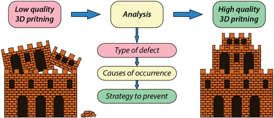
The FFF process involves the layer-by-layer application of thermoplastic material. A filament of material is fed into a heated nozzle, which makes it viscous before being applied to specific locations on the heated bed surface (Fig. 1a). When applied, the thermoplastic cools and solidifies.
![[{"id":"_XvA89n_H3","type":"paragraph","data":{"text":"Fused Filament Fabrication 3D printing: a) general principle; b) 3D printed part without defects; c) 3D printed part with defects."}}]](/storage/images/resized/u6kJD749wkyEXRmHIBuDhy6xlGqCnUJZhLaRhXxl_xl.webp)
In theory, this process should produce perfectly aligned geometries with strong interlayer adhesion (Fig. 1b). In practice, however, the heating and subsequent cooling of the thermoplastic — which causes expansion, compression, and, in some cases, changes in crystallinity 57 leading to high internal stresses — can lead to the formation of defects at both macro and micro levels (Fig. 1c). The occurrence of these defects can be attributed to inherent material characteristics (such as composition) or non-optimal printing parameters. It should be noted that the composition of commercial filaments can vary from manufacturer to manufacturer, with different plasticizer content and polymer chain length, which can, in turn, influence printing results and product properties.
Minimizing these defects is a major focus of current AM technology research, as it is the key to broadening the range of their practical applications. However, the lack of a comprehensive understanding of the mechanisms underlying defect formation and control often undermines the benefits of additive technologies. In many critical domains of technology development, the manifestation of defect structures is a significant setback and a limiting factor for 3D printing technologies.
3D Printing has become widely used in chemistry and other related sciences. The manufacture of chemical reactors using additive technologies is becoming increasingly popular. However, the formation of defects can lead to uncontrolled side processes during operation (for example, loss of the reaction mass in the pores of the material) or render the resulting reactors completely unsuitable for use. Understanding the causes of defects and knowing how to prevent them will make it possible to create high-quality reactors with specified performance characteristics.
The focus of this review is to analyze the defects that can occur in FFF printed products and discuss potential solutions for their elimination. For the first time, a systematic classification of 3D printing defects, and examination of them through various characteristics is described.
2. FFF printing defects
We analyzed important characteristics of 3D printing defects and developed their general classification (Fig. 2). The defects were classified according to geometric size, spatial topology, nature, and location (Table 1). The defect classification approaches were chosen for the following reasons. The size of the defect and its spatial topology have a primary impact on the ability to operate the product. The nature of the defect indicates what causes it and what parameters can be changed to prevent its formation. The localization of a defect makes it possible to predict possible side processes that may occur during the use of printed products. For example, in the case of a 3D printed test tube, the presence of voids in the outer layer will not affect its performance; in the case of a combined arrangement, this can lead to the accumulation of the reaction mass in the defect and consequently to its loss.
![[{"id":"CkGCzoyRlD","type":"paragraph","data":{"text":"Summary of defects according to their size dimensions."}}]](/storage/images/resized/ecF2YzaT4XgPy3T4D7vk4n0G8WfjBdoTqKOiZ1GU_xl.webp)
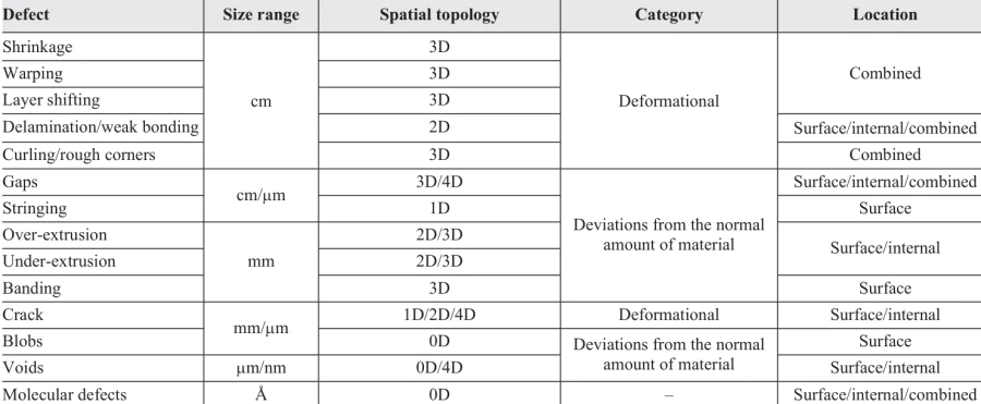
A detailed analysis of the literature has shown that defects can be of different sizes, ranging from centimeters to several nanometers or even angstroms. Defects differ in their spatial topology and can be point (0D) and linear (1D) as well as planar (2D) and bulky (3D). In addition, some defects tend to change their topology with time or exploitation, which makes it possible to separate them into a distinct group of spatial defects that change over time (3D + 1D = 4D). By their nature, defects are divided into two categories: those caused by deformation and those caused by deviations from the normal amount of feed material. One of the most important characteristics of defects is their location. They occur on the surface (external) of the product but can also be hidden in the volume of the material (internal). Defects propagating from the surface into the material are combined. Sections 2.1 – 2.5 of the review provide a more detailed overview of each defect presented in the table (see Table 1).
Description of defects is approximate, and they may have specific features. This is because the appearance of defects in the 3D printing process can be both regular and irregular/random. Improperly selected printing parameters and poor material quality causes regular defects. Irregular defects can be caused by a number of reasons:
1) the presence of extraneous impurities in the thermoplastic that partially clog the nozzle channel, resulting in insufficient material flow;
2) the formation of foulants inside the nozzle;
3) filament sliding in the feeder (e.g., PETG or polyethylene);
4) temporary deviations of printing parameters from initial settings (e.g., nozzle overheating or print speed increase/decrease).
In this review, for each type of defect, we consider only a small number of examples for illustration and classification. It was not the purpose of this review to list all possible works that mention defects.
2.1. Classification of defects by size
Defects in 3D printed products can be classified by size (see Table 1). Depending on their size, defects have varying degrees of impact on product properties. Large defects can render a printed part completely unusable, drastically alter the geometric shape, or significantly reduce strength properties. Small defects will not have such a significant impact on the properties of the part. According to this classification, defects can be divided into five types (see Fig. 2):
1) centimetric;
2) millimetric;
3) micrometric;
4) nanometric;
5) angstrom.
The centimetric defect group includes significant defects that can be as large as 1 centimeter or more. Such defects include shrinkage, warping, layer shifting, delamination/weak bonding, and curling/rough corners. Centimetric defects can also include gaps and stringing, although they are much more common in millimeters.
The millimetric range of defects can include defects with dimensions between 1 and 10 mm. This group of defects includes gaps, stringing, over- and under-extrusion, and banding. Cracks and blobs are extremely rare in the millimeter range. The micrometric size group includes cracks, blobs, and voids. The size of defects in this group ranges from 1 to 1000 µm.
The nanometric defect group includes defects less than 1 micrometer in size. Such defects may include voids. Angstrom size defects include the molecular defects (cleavage of chemical bonds and formation of new ones), resulting in the destruction of the polymer chain.
Defects reduce the mechanical strength and performance of printed products. Centimetric defects spoil the aesthetic appearance and cause the shape and dimensions of the product to deviate from the digital model. It should be noted that the larger the defect, the greater its impact on these characteristics.
Deterioration in mechanical strength due to product defects leads to accelerated structural change over time and wear in general. In some cases, small defects can lead to the formation of larger defects over time or during the use of the part. For example, closely spaced voids can lead to the formation of gaps.
Additionally, a combination of different defect types can form a larger defect when printed. For example, the formation of a void in a location where there is under-extrusion can lead to delamination. This can occur because the void acts as a stress concentrator in areas of insufficient material. An example of this phenomenon is the formation of layer shifting due to a combination of blobs, stringing, and over-extrusion. In such a case, the probability of the printhead catching on excess material is greatly increased.
However, over-extrusion can be used to make the printed part airtight. For example, by increasing the material feed rate so that the extrusion width is greater than the width calculated by the slicer, it is possible to eliminate the formation of voids and gaps of different sizes at each point of each extruded filament. It is also possible to cause over-extrusion at the points of contact between the inner filling and the perimeters of the part by increasing the value of the parameter responsible for perimeter overlap (outline overlap).
2.2. Classification of defects by spatial topology
Defects in products can be classified not only by geometric size scale but also by spatial topology (Table 1). In this case, the type of defect is determined by the ratio of the sides of the defect (Fig. 3). According to this classification, they can be divided into:
a) 0-dimensional;
b) 1-dimensional;
c) 2-dimensional
d) 3-dimensional;
e) 4-dimensional (changing in time).
![[{"id":"9W_df3vxTM","type":"paragraph","data":{"text":"Types of defects depending on spatial topology."}}]](/storage/images/resized/LSdTGKYw7p45F2aseijdGjZ6BwTLpajwCLX9Tmxz_xl.webp)
The first category includes point microdimensional defects (e.g., voids). One-dimensional defects include those that extend in one direction, i.e., linear defects such as stringing. Two-dimensional defects can include planar defects such as delaminated layers. Defects with dimensions of 1 mm or more are three-dimensional or bulky defects. These include gaps, warping, curling, etc.
A separate category (4D) includes defects that tend to change during product use. These include defects that are stress centers in the material. They contribute significantly to the reduction of the fatigue strength of the product — the strength of the product after long-term exploitation.58 – 61 Such defects may increase in size (e.g., cracks) and spread throughout the volume of the product.62, 63
Defects in the product lead to differences in material properties at different points. In addition, the dimensionality of the defects determines the directions in which the product properties will differ. For example, in the case of delamination, the tensile strength of the product will be lower when a load is applied across the layer than when a load is applied along the layer. In the case of rounded pores, however, the effect on the strength of the product is likely to be the same in all directions within a single layer.
2.3. Classification of defects by the nature of their occurrence
In addition to the above classifications, it is important to consider defects by the nature of their occurrence (see Table 1). In this regard, defects by their nature can be divided into 2 categories: those related to the deviation of the amount of material and those related to the deformation of the product.
The category of defects associated with abnormal amounts of material includes gaps, stringing, over- and under-extrusion, banding, blobs, and voids. They are caused by the poor quality of the material and improperly selected printing parameters, specifically those that affect the viscosity of the molten material and the speed of its application (extrusion multiplier, temperature and speed of extruder movement). An insufficient amount of material results in gaps, voids and under-extrusion, while excess material leads to occurence of stringing, over-extrusion, banding, and blobs.
The category of defects related to the deformation of the product includes shrinkage, warping, layer shifting, delamination/weak bonding, curling, and cracks. They are caused by poor adhesion of the material to the heating bed and poor interlayer adhesion. Another reason for these defects is improperly selected temperature conditions (printing and heating bed temperatures, as well as cooling intensity): if the product is cooled too fast during printing, and the material has a low thermal conductivity, thermal compression will occur unevenly at different points on the product, ultimately causing the product shape to deviate from that specified in the digital model. The study of thermoplastic melt deposition using computational fluid dynamics has shown that increasing the printing speed or decreasing the extrusion speed results in a reduction in the amount of material deposited. As a result, extrusion rate and hydrostatic pressure decrease, and consequently, the value of the deposited layer deformation decreases. Reducing the layer height also contributes to a lower degree of layer deformation.64, 65
2.4. Classification of defects by location
Depending on the location, defects are classified as surface, internal, and combined defects. Surface defects are those that are concentrated on the surface of the object without affecting the internal structure. These include, for example, banding, stringing and surface voids. Internal defects are located inside the product (in the near-surface layer or inside material) (e.g., internal gaps, voids, over- and under‑extrusion). Defects affecting both the internal and external structure of the product are combined. These include through voids as well as defects related to deformation (warping, shrinkage, curling/rough corners). Internal defects affect the strength properties of the product, and external defects determine the operating and friction properties. In addition, surface defects affect the resistance of the 3D printed object to external influences by increasing the surface area of the product and thus increasing the area in contact with the external environment. Defects of the same type with external and internal locations can propagate in the volume of the material during operation and join together to form combined defects.
2.5. Description of 3D printing defects
2.5.1. Shrinkage
Shrinkage is the property of a material to reduce its volume during solidification (Fig. 4). The effect is expressed as a percentage relative to initial volume.66 It depends on the melting point of the material, the temperature in the printing area, and the quality of the filament itself. The poor quality of the printing filament is due to its manufacture from raw materials with a high moisture content, which subsequently leads to the formation of shrinkage cavities and increases the shrinkage factor. The absence of special additives leads to an increase in the degree of shrinkage.
![[{"id":"Y9mEVJdLd2","type":"paragraph","data":{"text":"Schematic image of ‘shrinkage’ defect."}}]](/storage/images/resized/8s3YAT12LIcPxqF8a7rSQjUiOgFOO4EDr9lqG1Q3_xl.webp)
Increasing the layer height and printing speed helps to eliminate the defect.67, 68 The printing parameters must be chosen in such a way that as much material as possible is kept at a temperature that is high enough to prevent reduction in volume. This requirement is especially important when printing with thermoplastics with a high melting point (> 300 °C).69 However, it is also worth remembering that increased temperature of the part can lead to overheating and curling, stringing, and over-extrusion.
2.5.2. Warping
Warping is a defect that represents a change in the flatness of the printed part (Fig. 5). It can be detected visually and by measuring tools.70 Warping is caused by thermomechanical stresses in the part as it cools during the printing process. Stress is caused by a decrease in the specific volume of the polymer during uneven cooling.71
![[{"id":"0o4FUQCZxy","type":"paragraph","data":{"text":"Occurence of the defect ‘warping’ during 3D printing: (<i>a</i>) schematic image of warping; (<i>b</i>) warping of a cuboid print model.<sup>72</sup> The figure (<i>b</i>) is published according to Open Access Creative Commons License 4.0."}}]](/storage/images/resized/5qr16dCt2HrsxBe2sNNEMIICIj0pbhs7eEWkUZ0O_xl.webp)
The formation of the described defect is largely influenced by the geometric parameters of the part: length-to-width ratio and height.73 Additionally, this is affected by printing settings: wall thickness and infill percentage.74 A dirty heating bed surface, inappropriate adhesive, and excessive cooling of the part can enhance the defect.75, 76
The defect affects the geometry of the part. It can cause the part to be unusable for its intended purpose due to significant changes. It can also cause an emergency print stop because the nozzle is blocked by a raised part of the part.
The following methods can be used to prevent warping or minimize its effects:
1) Keep the ambient temperature constant. Temperature variability (seasonal or random fluctuations) increases the probability of warping. Printing indoors can reduce the risk of warping. In the ideal case, an isolation chamber can be used around the printer.
2) Degrease the surface of the heating bed. Clean the surface with a special composition, or, in a simple case, a 90% solution of isopropyl alcohol, acetone or glass cleaner.
3) Use a different work surface to increase surface adhesion, such as special tape or Kapton tape, glue, or glass with a rough surface.77
4) Reduce the infill percentage to the optimal value. A high infill percentage will increase stresses and cause deformation of the part. Avoid using more than two or three perimeters.
5) Increase the brim (stabilizing base that is additionally printed along the perimeter of the part to improve adhesion to the heating bed; it doesn’t contact the part).
2.5.3. Layer shifting
Visually, the layer shifting defect is the incorrect positioning of the layer relative to the previous layer (Fig. 6). This defect is characterized by a shift appearing along the X or Y axis. The size of the defect can be smaller than the extrusion width and does not lead to serious geometric deviations or a drastic decrease in the physical-mechanical properties of the part. A larger defect can lead to a negative printing result, where the layers shift so much that they do not touch the already printed part of the object.
![[{"id":"X_d4XRvrtw","type":"paragraph","data":{"text":"3D printed objects with shifted layers: (<i>a</i>) schematic image of layer shifting; (<i>b</i>) layer shifting caused by incorrect axis movement;<sup>75</sup> (<i>c</i>) layer shifting during FFF printing of PLA part.<sup>78</sup> The figures (<i>b</i>) and (<i>c</i>) are published according to Open Access Creative Commons License CC BY 4.0."}}]](/storage/images/resized/exdOmebegR3w7wMFBAfEK970SFHsYbwYF7Ry8UZB_xl.webp)
Layer shifting can be caused by improper movement of the extruder, blocked axis movement, pulley loosening, and complex part geometry that is difficult to print.75
The formation of the defect leads to discrepancies between the geometric parameters of the part and the 3D model, deterioration of strength properties, and loss of structural integrity of the printed part.
To prevent the occurrence of the defect, it is necessary to check the moving parts of the positioning system axes for mechanical damage and backlash. It is also advisable to design the 3D model to avoid geometries that are difficult to print, especially for models with large overhanging parts that tend to deform during printing.
2.5.4. Delamination/weak bonding
One of the disadvantages of FFF printing is the layered structure of the product. This results in anisotropy of the mechanical properties. For example, the tensile strength of the products is higher when loaded in the longitudinal (along layers) direction than when loaded in the transverse direction (across layers).79 – 82 Anisotropy of mechanical properties can be reduced by using ultrahigh extrusion widths.83
However, in some cases, weak bonding of the layers can be observed, which can cause delamination. Delamination/weak bonding appear as breaks that form along the direction of the layer and occur only between layers (Fig. 7).84, 85 Most often, this defect starts at the corners and perimeters of the part and then spreads along the layer. A smaller defect (e.g. pores), which becomes a stress concentrator, can also act as a trigger for delamination.
![[{"id":"AuTmXIura-","type":"paragraph","data":{"text":" Delamination: (<i>a</i>) schematic image; (<i>b</i>) delamination on polyamide parts.<sup>84</sup> The figure (<i>b</i>) is published according to Open Access Creative Commons License CC BY."}}]](/storage/images/resized/jQMlypSuGrQOODCWCnfIJXr3htybuDLMBFLtbtS1_xl.webp)
The defect occurs when internal stresses are higher than interlayer adhesion. The formation of defects is influenced by the shrinkage coefficient of the material, insufficient extruder and heating bed temperatures, and excessive fanning or cooling of the part. Delamination leads to a deterioration of the physical and mechanical properties of the part up to its complete unusability.
To avoid this defect, a constant ambient temperature should be maintained, covers should be installed to protect the printing area from air currents, and the printing temperature was increased by 5 – 10 °C to reduce viscosity and improve interlayer adhesion.75
One of the most important characteristics of 3D printed products is mechanical strength, which depends on the strength of the interlayer bonding. This parameter is determined by the degree of diffusion of polymer molecules from the adjoined layers. This parameter can be improved by reducing the viscosity of the deposited material and the time it remains in a viscous-flow state.80 This is achieved by increasing nozzle temperature, reducing printing speed and using a heated chamber. Reducing the layer thickness also increases the interlayer bonding strength.86, 87
2.5.5. Curling/rough corners
The curling visually resembles warping but is formed in the upper corners of the part (Fig. 8). It is a deformational defect. The curling is caused by overheating.75, 88, 89 Overheated or insufficiently cooled material can stick to the nozzle and the material coming out of the nozzle. Overheating also causes the material to spread out, which promotes defect formation.
![[{"id":"yNR-b_Vwxh","type":"paragraph","data":{"text":"Schematic image of ‘curling’ defect."}}]](/storage/images/resized/UwHBShEyHpB8O90BvEbHav8MUwlyQFphXoKbCWrj_xl.webp)
The presence of the defect affects the geometry of the part. To avoid this, the printing speed should be reduced to give the part additional time to cool, the fanning intensity in the printing settings was increased, and the extruder temperature was reduced by 5 – 10 °C. However, care should be taken when changing parameters that affect the temperature regime during printing, as this can cause a number of defects related to insufficient temperature of the material, part, and print area.
2.5.6. Gaps
Gaps are spatially localized areas without material (cavities) (Fig. 9). They can have different shapes (from round to elongated) and sizes up to 1 mm or more.90, 91 Gaps are localized both within the layers (at the perimeter and in the depth) and between them. The reason for their formation is weak bonding (adhesion) both between the layers (in the case of interlayer gaps) and between individual strands. Weak adhesion due to low melt flow and diffusion with the relatively rapid cooling of the material after application, resulting in compression of the material, leads to increased material stress between bonded layers/filaments.92, 93 This leads to a reduction in the mechanical strength of products, as well as the permeability of thin-walled products in the case of through cavities.94 – 101 Higher extruder 102 and heating bed temperatures,103 lower printing speed,104, 105 lower layer heights and greater extrusion widths 103 all contribute to a reduction in gap size and number. Increasing the infill percentage also helps to reduce the overall internal porosity of the product. Additionally, surface gaps can be reduced with ironing, which allows smoothing of the top layer, resulting in a decrease in surface roughness.106
![[{"id":"XrRiLuYzsJ","type":"paragraph","data":{"text":"Schematic image of ‘gaps’ defect (top view of the layer)."}}]](/storage/images/resized/6ItAMsfYET7R1UY2QmnmKbHwv3h2iRD2L9c4wjId_xl.webp)
2.5.7. Stringing
Stringing (or oozing) appears as threads of material hanging between the separately arranged parts of the 3D printed object (Fig. 10).107 This results in the need for post-processing to remove the threads. They are caused by the printing material remaining on the outside of the nozzle when it is moved without the thermoplastic being applied. This can be caused by an uncontrolled flow of material due to too high extruder temperature.88 Stringing may result in deviation of the end product from the specified shape and dimensions. To reduce the severity of this defect, it is necessary to reduce the printing speed and extruder temperature and increase the retraction distance. The last parameter indicates the pulling of material inside the nozzle when the nozzle is moved without applying thermoplastic. Proper calibration of the bed along the Z-axis is also important.
![[{"id":"TVxfEf-F4c","type":"paragraph","data":{"text":"Stringing defects in 3D printed objects: (<i>a</i>) schematic image; (<i>b</i>) a small object deformed by the formation of stringing.<sup>108</sup> The figure (<i>b</i>) is published according to Open Access Creative Commons License CC BY 4.0."}}]](/storage/images/resized/HAvqaqIg1WPHs6zWXvrv0NsLwveCjA7BGZ78Rbd9_xl.webp)
2.5.8. Over-extrusion
Over-extrusion is overfeeding that results in the product being inconsistent with the digital model (Fig. 11).109 This is caused by high extruder temperatures and feeding rates. This defect can be localized or widespread throughout the material. In the first case, the defect may also be caused by a decrease in extruder movement speed during printing when turning.110 Over-extrusion results in deviation of the product from the specified shape and dimensions and slightly increases the mechanical properties of the product (tensile strength).111 To prevent this defect, it is necessary to decrease the extruder temperature and feeding rate.74, 112
![[{"id":"oL8NWzmxM5","type":"paragraph","data":{"text":"Over-extrusion: (<i>a</i>) schematic image (top view of the layer); (<i>b</i>) defects in objects 3D printed with PLA.<sup>109</sup> The figure (<i>b</i>) is published according to Open Access Creative Commons License CC BY 4.0."}}]](/storage/images/resized/P2Zu59F3SVPJXw8PjeASIxcO0LyE4xCoA3YpYgGi_xl.webp)
2.5.9. Under-extrusion
Under-extrusion appears under the influence of opposite factors compared to over-extrusion. It occurs when an insufficient amount of material is applied, which is less than the amount specified in the digital file (Fig. 12).112 This leads to the formation of gaps and voids both within and between the layers, as well as reduced mechanical properties of the resulting products.111 This is caused both by an insufficient material feeding rate (extrusion multiplier) and by an extruder temperature that is low for the material. To prevent this defect, it is necessary to increase the extruder temperature as well as the material feeding rate.75
![[{"id":"1x4Cjk_bN1","type":"paragraph","data":{"text":"Under-extrusion: (<i>a</i>) schematic image (top view of the layer); (<i>b</i>) defects in objects 3D printed with PLA.<sup>111</sup> The figure (<i>b</i>) is published according to Open Access Creative Commons License CC BY 4.0."}}]](/storage/images/resized/fxy54uZDL26f9oktWEyBjcWj6EWELLcU2jxYOUrn_xl.webp)
2.5.10. Banding
Banding refers to the uneven vertical/sidewall surface of the printed product. It can appear as clearly defined convex lines/layers on the side of the product or as a wavy surface (Fig. 13). The causes of this defect are extrusion of an insufficient amount of material, as well as wobbling. Wobbling is unclear positioning of the heating bed along the Z-axis. It is caused by distortion or weak fixation of the lead screw, which is responsible for raising and lowering the table during printing.113 – 116 This defect affects the aesthetic appearance as well as the frictional properties of the 3D printed object. To prevent the appearance of this defect, it is necessary to eliminate the causes described above. If under-extrusion occurs, check whether the nozzle is clogged with material or increase the extrusion multiplier and/or extruder temperature.
![[{"id":"cnGJRywyvb","type":"paragraph","data":{"text":"Schematic image of ‘banding’ defect."}}]](/storage/images/resized/qusnLaz7KGx7UongAhaE5NapXbpZQe6R7kC4p23f_xl.webp)
2.5.11. Cracks
Cracks may appear and spread in the products during printing in the case of materials filled with ceramics, metals, carbon materials, etc. They affect the fatigue strength of products and can propagate in 3D printed objects during operation and under load (Fig. 14).62, 117 – 121 Cracks grow in the material along the weakest points. Therefore, they are more likely to form between layers and along the thermoplastic path during printing.63 The formation of cracks under load can be initiated by voids acting as stress concentration points. Therefore, reducing the porosity of the product will increase the resistance of the material to cracking under pressure, which is facilitated by reducing the layer height during printing.122, 123 At the same time, based on bending tests, the authors 124 argue that increasing the nozzle size and layer height helps to reduce the rate of fatigue crack growth.
![[{"id":"S5lPO5xwMK","type":"paragraph","data":{"text":"Schematic image of ‘cracks’ defect."}}]](/storage/images/resized/cfcjCsWYrm0fDDtquY6PgkKpTi95FrHCiq4QZsq2_xl.webp)
2.5.12. Blobs
Blobs appear as bubbles or swells on the surface of the part (Fig. 15). The defect can be caused by incorrect filament retraction settings at the start and end points of movement.72 Bubbles and swells can also be affected by the stability of the filament diameter. The defect impacts the geometric and aesthetic properties of the printed part. The nozzle can catch on larger swells, causing layer shifting or unexpected print stops. It is recommended to use filaments without significant thickness deviations to correct the defect. If the defect is not due to the quality of the filament, it is recommended to find the correct filament retraction settings.
![[{"id":"3o-hMhZxv1","type":"paragraph","data":{"text":"Blobs: (<i>a</i>) schematic image; (<i>b</i>) defects in objects 3D printed with PLA.<sup>125</sup> The figure (<i>b</i>) is published according to Open Access Creative Commons License CC BY 4.0."}}]](/storage/images/resized/GGs2cCrNMRlEZYxiwupKtERyBjat2Fhbfmu4BGAe_xl.webp)
2.5.13. Voids
Voids (or pores) are areas of the product that are not filled with material. Unlike gaps, pores are smaller in size (on the order of hundreds of microns or less).126 Like gaps, pores can form on the surface of the article and in the near-surface layer, as well as within and between layers (Fig. 16).127 The porosity of the product leads to a deterioration of its mechanical properties.128, 129 The presence of pores reduces the tensile strength and maximum load of the products.130, 131 Surface pores reduce the resistance of the product to external influence by increasing the area of contact between the product and the environment. As a result, the fatigue strength of the product decreases.60 Interlayer pores critically affect strength properties, especially when the load is applied perpendicular to the layer, because they can cause delamination.132, 133 When the products are in use, voids can give rise to cracks. As with gaps, the appearance of interlayer pores can be caused by poor adhesion of the material layers during printing, which can be prevented by increasing the printing temperature and reducing the layer height.134 It was shown in 135 that a gradual increase in the extrusion rate reduces the number of pores to a minimum. The use of a square-shaped nozzle also helps to reduce the number of pores.136 According to computational fluid dynamics simulations, reducing the layer thickness results in lower porosity.137 Another cause of pores can be inconsistent material flow due to moisture in the filament. For this reason, predrying the filament should solve the problem. Environmental humidity also contributes to the porosity of a 3D printed part.138 A reduction in porosity can be achieved by several post-processing techniques. Therefore, chemical treatment of the printed product with a solvent (by immersion) or its vapor leads to surface smoothing and a reduction in surface pores.139, 140 Annealing (heating the printed product to a temperature between the glass temperature and the melting point, followed by gradual cooling) promotes stress redistribution within the product and, in the case of semicrystalline materials, increases crystallinity, tensile and strength properties.141 – 146 In the case of amorphous polymers, such as ABS, annealing has been shown to reduce the overall porosity of the product.147
![[{"id":"OS_BphhT-g","type":"paragraph","data":{"text":"Voids: (<i>a</i>) schematic image; (<i>b</i>) defects in objects 3D printed with PLA.<sup>148</sup> The figure (<i>b</i>) is published according to Open Access Creative Commons License CC BY 4.0."}}]](/storage/images/resized/Tv0vw40fxQsbdK5RyRN12VushxRC8tACrsBptpsD_xl.webp)
2.5.14. Molecular defects
Overheating of the filament during printing can cause thermal decomposition of the polymer by cleavage of chemical bonds and destruction of the polymer chain. This process is accompanied by the formation of new compounds with properties different from those of the original polymer. This can lead to the formation of nonhomogeneous material properties in the product, as well as give rise to other defects (e.g., pores). In addition, in some cases, the decomposition of the polymer results in the release of gases, some of which are toxic. For example, it is known that overheating of polyoxymethylene during printing can lead to its decomposition with the release of formaldehyde vapor (Scheme 1a).149 Auto-oxidation of POM in the air begins at 160 °C (Scheme 1b).
![[{"id":"wrwjqIFrYs","type":"paragraph","data":{"text":"Transformations of POM upon heating: (<i>a</i>) depolymerization; (<i>b</i>) aerobic oxidation."}}]](/storage/images/resized/ZRCYtY5LWfbjs7uU2sglemY8BSidUUpKu9JJfTtp_xl.webp)
It should be noted that the mechanism of thermal decomposition of the polymer is determined by its nature and the variety of chemical bonds in it (C – C, C – O, etc.). It has been shown that polyethylene terephthalate (PET) undergoes degradation at 450 °C. The degradation is accompanied by the cleavage of ester bonds, resulting in the formation of CO, CO2, benzoic acid and its derivatives, as demonstrated by infrared spectroscopy (Scheme 2).150, 151
![[{"id":"J2JUJewUbw","type":"paragraph","data":{"text":"Chemical transformation of PET leading to the cleavage of the polymer chain."}}]](/storage/images/resized/oI12VFqug1KQuRH473c93MlgUEBOHl6RNiDCDgvs_xl.webp)
Materials widely used in FFF printing, such as PLA, ABS and Nylon, are also subject to thermal decomposition even at temperatures comparable to the printing temperature. Heating samples of these materials at 240 – 250 °C for 10 min resulted in the release of a mixture of volatile products consisting of acetone, butadiene, styrene, isobutanol, ethylbenzene, and cyclohexanone (in the case of ABS), acetone, methyl methacrylate, isobutanol, and cyclohexanone (in the case of PLA), and propylene glycol and cyclopentanone (in the case of Nylon).152 To prevent this defect, it is necessary to use high-quality filaments and to control the printing conditions to avoid local overheating of the material.
Thermoplastics can age if stored under inappropriate conditions. In the case of polylactide, for example, hydrolytic degradation of the material can be observed when the temperature rises above 37 °C, leading to a decrease in the molecular weight of the polymer and a deterioration in the mechanical properties of printed products.153, 154
3. Defects in FFF printing with reinforced materials
Composite materials for FFF printing have become widespread.155 Thanks to various fillers, such as carbon fiber, glass fiber, and other types of fibers, as well as various metal particles, nanotubes, standard printing materials acquire specific characteristics, including increased operating temperature, improved mechanical properties, altered current and thermal conductivity, etc.156 – 160
The defects described in the previous sections of our review fully apply to composite materials; however, such materials have a number of inherent defects associated with the presence of dispersed fillers in the material. The most significant impact defects are the uneven distribution of fibers in the polymer matrix and weak bonding between composite particles and the polymer matrix (Fig. 17, Fig. 18).162, 163 These defects are related to the manufacturing process of the composite material for FFF printing and require a review in a separate article.
![[{"id":"WCbOVwKNqp","type":"paragraph","data":{"text":"SEM images of tensile fracture surfaces of 3D printed 10 wt.% carbon fiber-loaded polyamide-6 composite (PA6-CF10).<sup>161</sup> The figure is published according to Open Access Creative Commons License CC BY 4.0."}}]](/storage/images/resized/Lx0CMJxtRIvsnkqyWnSVatk3RFDEUUezLhv7rNg2_xl.webp)
![[{"id":"X8QK1Wvf9P","type":"paragraph","data":{"text":"Image of polished cross-sections of filaments of continuous carbon fiber (CF) loaded polyphtalamide (PPA).<sup>164</sup> The figure is published according to Open Access Creative Commons License CC BY 4.0."}}]](/storage/images/resized/IpjNYbMrnAiFQzLQN4UwSwyF6UmzEvp93ELUjVRy_xl.webp)
When producing parts from composite materials using the FFF printing method, it is worth considering a number of features related to the properties of the material:
1) Due to the presence of dispersed filler in the material, the possibility of nozzle clogging increases, which can lead to uneven extrusion until it stops completely and printing is interrupted. Additionally, a clogged nozzle can lead to the formation of pores and gaps. To minimize the risk of nozzle clogging, nozzles with an outlet diameter greater than 0.4 mm should be used.
2) Due to the presence of a dispersed filler in the material, which increases the abrasive properties of the extrudate, the service life of standard nozzles made of brass is significantly reduced. Nozzle wear will lead to a significant change in the diameter and geometry of the outlet, which in turn will significantly affect the geometric shapes of the printed product and the accuracy of the printing characteristics to the point where it is impossible to use the part for its intended purpose (Fig. 19). Depending on the amount and type of reinforcing fiber, such wear can occur when processing small quantities of material, up to several tens of meters of filament. To minimize the risk of rapid nozzle wear, it is worth using steel, carbide, ruby, sapphire or other nozzles made of high hardness materials.
![[{"id":"0JmHvQ0gru","type":"paragraph","data":{"text":" (<i>a</i>) New nozzle; (<i>b</i>) worn out nozzle after printing with composite material (Illustration by the authors). (The figure is from the authors’ archive for the work <sup>51</sup>)."}}]](/storage/images/resized/wqueOZkzG1IY7Y1x87UZuVuZmShYMDpYXyXIvdG1_xl.webp)
4. Influence of defects on quality of 3D printed reactors
Additive manufacturing technologies are increasingly used in the chemical industry and laboratory practice. Quick prototyping and creating products with complex internal structures are among the notable advantages. It has been shown that chemical equipment, batch and flow reactors, sensors and catalytic structures can be manufactured using 3D printing. A number of reviews are devoted to the use of additive technologies in chemistry.19, 165, 166
However, the formation of defects can lead to uncontrolled processes during operation (for example, loss of the reaction mass in the pores of the material) or make the resulting reactors completely unusable for practical applications. The degree to which a defect affects the functionality of a product is determined by the size/type of the defect and the structure of the reactor. The larger the size of the defect relative to the size of the reactor, the higher the probability of its failure. For example, product shrinkage may result in dimensional deviations from the digital model, which in the case of composite products consisting of several individual parts may result in poor fit. If there are internal channels in the device, shrinkage, over-extrusion and stringing can lead to a decrease in their diameter or filling with material. In the case of thin-walled products (test tubes, flasks, etc.), delamination, under-extrusion, gaps, voids and cracks increase the probability of damage to the integrity of the wall. This can lead to leakage of the reactor, as well as to the penetration of the reaction mass through the walls and its loss. Reactor leakage is especially critical in the case of gas-phase processes since gas, especially at elevated pressure, can penetrate through small voids (Fig. 20).
![[{"id":"OHCms9hM7A","type":"paragraph","data":{"text":"Non-tight 3D printed tube and flask.<sup>98</sup> The figure is published according to Open Access Creative Commons License 4.0."}}]](/storage/images/resized/yug7Us3rMotLudyNFkrdJXFt0hEbWMHACZeA08vV_xl.webp)
The porosity of printed products is an important drawback of 3D printing, causing leakage in reactors (e.g., test tubes and other reaction vessels). However, it is determined by the 3D printing parameters, particularly the extrusion rate. As it increases, the total pore content decreases. So, it has been shown that FFF printing can be used to manufacture reactors for carrying out the solvothermal synthesis of metal-organic frameworks, which is accompanied by an increase in temperature and pressure.167
5. Application of artificial intelligence to improve the quality of 3D printing
The application of neural networks to solve various problems in science and technology is becoming increasingly popular. In the field of additive manufacturing, artificial intelligence is used to improve the quality of the fused filament manufacturing process, namely, to optimize the set of printing parameters.78, 85, 168 – 170 There have been a number of papers, devoted to the development of neural network-based pipelines for predicting the properties of printed products depending on the selected set of 3D printing parameters (for example, tensile strength).171 – 175
Another area of application for neural networks is the online detection of defects in the 3D printing process. To detect defects, neural networks are used in combination with computer vision, using product snapshots taken with high-resolution cameras or digital microscopes.116, 176, 177 Neural networks are first trained on sets of images. Other types of signals are also used as input data. For example, the authors of the work 178 used a thermographic system to heat samples and then record cool-down data. A number of works provide examples of the use of neural networks to detect defects of a specific type, such as warping,179, 180 and stringing.108
6. Conclusion
3D Printing represents a revolutionary step in the field of innovative manufacturing technologies. At present, numerous printing methods have been developed, facilitating the production of items from a wide range of materials. However, the optimal selection of printing parameters remains of paramount importance, as it has a profound effect on the performance characteristics of the manufactured products. This review examines a variety of defects inherent in products created by one of the most prevalent methods — Fused Filament Fabrication — and analyzes their influence on the properties of the resulting products.
Defects occuring in FFF 3D printing processes are classified based on size into centimetric, millimetric, micrometric, and nanometric categories. The size of a defect directly affects product strength, with larger defects leading to greater deviations in strength characteristics. Dimensionally, defects have been catalogued as 0-, 1-, 2-, 3-, and 4-dimensional defects. The dimensionality of the defect influences the anisotropy of the strength of the part in different directions relative to the defect within a single layer.
The origins of defects can be traced to both material properties (e.g. high coefficient of thermal expansion) and improperly selected 3D printing parameters (material feeding rate, layer height and width, extruder and bed temperatures). The nature of the defect could be related to a discrepancy in the volume of material applied compared to the predetermined amount or to the deformation of the part during cooling. In terms of location, defects can be categorized as external (surface), internal, and combined (affecting both the internal and external structure of the part).
Upon classifying the defects by size, type, category, and location, it has been shown that the defects within the deformation group are predominantly within the centimeter size range. Therefore, these defects have a greater impact on the properties of the part and operational characteristics.
Every defect has been carefully discussed, providing an external description, explicating the impact on the properties of the printed structures. Thus, for the first time, a list of defects is formulated in descending order of size, including shrinkage — a defect signifying the reduction in material volume as it solidifies; warping — the alteration of flatness of the printed part; layer shifting, having the form of misaligned layers relative to the preceding one; delamination/weak bonding — interlayer breaks that form along the layer’s direction; curling (rough corners) — a temperature defect on the upper corners of the part; gaps, ranging from round to elongated material passes; stringing — strands of material sagging between parts; over-extrusion of material; under-extrusion, indicating a lack of material; banding — rough areas on the vertical or side surface of the part; cracks; blobs — bubbles and swells; voids — shallow cavities that remain unfilled with material; and, molecular defects leading to cleavage of chemical bonds and formation of new ones. This list of defects will be further extended as more are described in the literature.
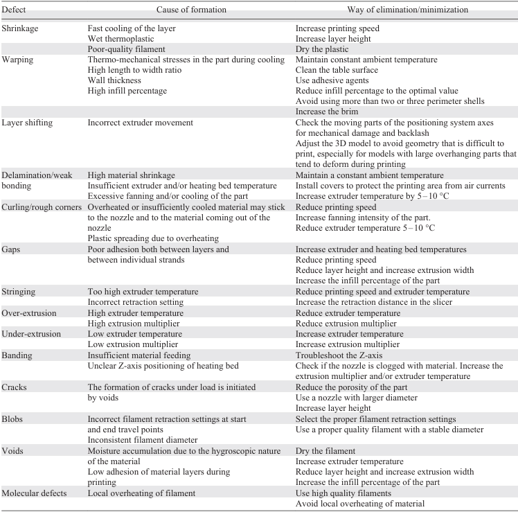
The review describes the causes of each of these defects and proposes methods to mitigate them via the appropriate selection of 3D printing parameters (Table 2). It suggests that the most influential 3D printing parameters impacting overall product defects are the extruder temperature and printing speed, in addition to the material feeding rate. Nonetheless, each material requires its own set of printing parameters, determined both by the inherent properties of the material (glass transiton and melting temperature, adhesion, thermal expansion coefficient) and the desired performance characteristics of the final product (strength, weight, etc.). Table 1 and Table 2 represent the first compilation of defects, origins of their appearance and possible remediation. Further factors and solutions may be added in the future, as well as corrections may be applied upon gaining a deeper insight.
Analysis of the presented data shows that using FFF printers it is possible to obtain high-quality, predictably performing products. In this regard, we believe that the topic of defect formation deserves close attention. Developing defect classification characteristics, understanding the mechanism of defect formation, and methods of prevention have significant practical relevance.