![DOE’s target (2025) PEMFC component characteristics. Refs. [5, 32, 36, 59-71]](/storage/images/resized/IJzHCUk3rsttN4hsEqNP2PWcAsc12WO1Kgjh5nmk_xl.webp)
![Characteristics of industrially manufactured PEMFCs. Refs. [85, 86, 88, 90, 96, 97]](/storage/images/resized/qhYZR3mDP93oHvPiLM8ucyLGJihML7uitOtvaZUz_xl.webp)
![Optimum air stoichiometry (grey dashed line) at different load currents[41].](/storage/images/resized/0vkLiz7tVj2IYRfzftumHdDi0yNi566AjSaRIeW9_xl.webp)
![Diagram of hydrogen oxidation energy utilisation in PEMFCs[273].](/storage/images/resized/jFOIVJfKROfz24PyQ7HaQo1YH50ueNd67SD8pTrJ_xl.webp)
![Cooling systems of PEMFC of different capacities[278].](/storage/images/resized/0MWoq537pnNRU5OBTpelWbnBgx27UgEh8DFJF3WE_xl.webp)
Keywords
Abstract
Over the last decade, the potential of proton exchange membrane fuel cells (PEMFCs) for use in a range of applications, including automotive transport, has attracted the attention of scientific groups and industry representatives worldwide. The active development of PEMFCs is already enabling them to compete with internal combustion engines and lithium-ion batteries in a number of applications. However, significant improvements in a number of PEMFCs characteristics are required to expand the scope of their applications. This review is intended to bridge the gap between existing reviews, which are either overly general or overly specific, and provide a comprehensive overview of the current state of the art and potential future applications of PEMFCs. It will focus on the main components of PEMFCs, including proton exchange membranes, catalytic and gas diffusion layers, bipolar plates, and cooling systems, and the factors affecting the PEMFC performance.
The bibliography includes 428 references.
1. Introduction
In recent years, there has been a trend to reduce the consumption of carbon-containing fuels due to their negative impact on the environment and to switch to alternative energy sources. Renewable energy sources (in particular, solar or wind energy) can be used for a number of tasks, but insufficient power density prevents their use for transport, portable and mobile applications. For these purposes, internal combustion engine (ICE) systems and electrochemical devices such as batteries are actively used, but they are inferior to fuel cells (FCs) and power plants based on them in a number of parameters. FCs are one of the elements of the hydrogen energy technology, which has been actively developed and implemented in recent years[1-5]. To date, FCs have been developed in a wide power range, from a fraction of a watt to hundreds of kilowatts, and the scope of their application is gradually expanding due to improved technology and reduced cost.
There are various types of FCs. Due to the lack of a universal classification system for FCs, they are usually first classified according to the type of electrolyte. This feature makes it possible to distinguish the following main types of FCs: with proton exchange membrane (solid-polymer), solid oxide, alkaline, phosphoric acid and melt-carbonate. Secondly, the classification is made according to the type of fuel reagents used, such as hydrogen-air, alcohol, etc. In recent years, a significant number of articles have been published on the principles of operation, advantages and disadvantages of each of these devices, including reviews (e.g. publications[6-21]). This review will not describe in detail all existing types of FCs. Instead, it will focus on hydrogen-air proton exchange membrane fuel cells (PEMFCs), also known as solid polymer fuel cells. PEMFCs are regarded as the most promising in terms of their application in various fields, including stationary (power plants, backup power sources, autonomous power supply)[20, 22-25] and transport (cars, buses, aviation, railway transport)[19, 25-33]. Various global corporations are already commercially producing cars, trucks and buses using PEMFCs. The main advantages of PEMFCs over other types of FCs are as follows: high technology, relatively high lifetime, fast start-up, wide power scalability, and high specific power. Consequently, the specific power of the fuel cell stack (FCS) (without consideration of the coolant and associated equipment) in passenger cars exceeds 4 kW kg–1.
Specific power and lifetime are among the key characteristics of PEMFCs. Despite large-scale developments in the field of PEMFCs, the required power of 5 kW kg–1 and lifetime of 50 000 hours for these devices have not yet been attained. These parameters are determined by the complex properties of each of the components that make up the PEMFCs, and therefore further research into efficient materials is required to achieve them.
Most existing reviews on PEMFCs are either too general (e.g. works[32, 34, 35]) or too specialised (focusing on only one component of PEMFCs[36, 37] or, for example, on degradation mechanisms[38] or water balance[39]). Furthermore, there is a lack of focus in the literature on the mutual influence of the material properties of the components, especially under different device operating conditions. This is an important factor for achieving the required PEMFC performance.
This review is designed to address a specific information gap. It collates and categorises information on all components and factors affecting the efficiency and lifetime of PEMFCs. The review will be of interest to a wide range of readers, including specialists in the field, early career scientists and industry representatives. It will provide a comprehensive overview of recent developments and help to understand future research directions.
This review does not address the degradation of PEMFC components, ‘cold starts’, the influence of mass and dimensions, geometry, and other technological aspects (e.g., methods of controlling PEMFC operation[40-42] or power management[43]), as their description would have required a much longer review.
2. Operating principle of fuel cells. Proton exchange membrane fuel cells: types, design features
2.1. Main operating principles
Fuel cells are electrochemical devices that convert chemical energy (Gibbs free energy) of reactants directly into electrical energy (direct current). At such conversion there are no typical for ICE limitations in efficiency determined by the Carnot cycle and intermediate thermomechanical processes of energy conversion (Figure 1), which makes it possible to increase the efficiency of FCs in comparison with ICE. The FC is an energy conversion device, not a storage device. Fuel and oxidiser are stored outside the FC and supplied into it as they are consumed.
![[{"type":"paragraph","data":{"text":"Scheme for converting chemical energy into electrical energy in two ways (in ICE and in FC)."}}]](/storage/images/resized/Yvi6D70T5TJRgSVkuu5VPuHpKSdVruHAfww4PyCl_xl.webp)
The fuel in the PEMFCs under review is hydrogen, while the oxidising agent is aerial oxygen. The main functional part of a single FC (Figure 2) is the membrane-electrode assembly (MEA), which consists of three main elements:
![[{"type":"paragraph","data":{"text":"Schematic of a single PEMFC."}}]](/storage/images/resized/ShfAyfTWX5VD7kCiLyGdfnvE5c9nHKoAAkALdMS4_xl.webp)
1) the polymer electrolyte membrane (PEM), the main functions of which are to transport protons from one electrode to another and to separate the electrode spaces;
2) the catalytic layer where electrochemical oxidation and reduction reactions take place;
3) the gas diffusion layer (GDL), which provides supply of the reagents to the area of electrochemical reaction, as well as water balance and current carrying.
Another essential component of the PEMFC is the bipolar plate (BP), which fulfils several functions. These include facilitating the serial connection of multiple MEAs to boost the total electrical voltage of the FCS, providing hydrogen and air supply through channels, and also participating in the process of heat exchange with the environment. Further details on the PEMFC components can be found in the following sections.
The operating principle of PEMFC is based on electrochemical reactions. The hydrogen electrooxidation reaction (HOR) occurs in the anode space:
where \( E^0 \) is the electrode potential relative to the normal hydrogen electrode (NHE) for the electrochemical process occurring at the electrode. The protons and electrons formed during this reaction, after passing through the PEM and the external electric circuit, participate in the oxygen electroreduction reaction (ORR) of air in the cathode region. The main product of this process is water:
A by-reaction with the formation of hydrogen peroxide is possible[44]:
The general reaction in a PEMFC is:
A number of thermodynamic parameters are used to describe all chemical reactions, including electrochemical reactions. In the case of electrochemical reactions, it is more convenient to pass from thermodynamic parameters to electrochemical parameters. The relationship between them is defined by the fol
where \( V \) is the voltage between the electrodes, \( \Delta Q \) is the change in heat, \( z \) is the number of electrons involved in the reaction (\( z=2 \) for reaction (4)), \( F \) is the Faraday constant. The thermoneutral voltage is calculated from the change in enthalpy of
However, in reality \( V_t \) is unachievable. Under standard conditions (1 atm. pressure and 25 °C), the open circuit voltage (\( V_0 \)) for an electrochemical system is determined by the change in Gibbs free energy (\( \Delta G^0 \)).
The liquid and gaseous water formation has a standard Gibbs energy change of –237.34 and –228.74 kJ mol–1 respectively[45]. For the water formation process (4) occurring in PEMFC:
In real conditions, the value of the open circuit voltage VOC will be lower than 1.23 V (\( V_0 \)) due to the HOR and ORR occurring under conditions other than standard conditions (this process corresponds to the equilibrium value of the FC open circuit voltage, \( V_N \), determined by the Nernst equation) and the diffusion of reagent gases from one electrode space to another (gas permeation, crossover) (Figure 3a).
![[{"type":"paragraph","data":{"text":"Typical view of the FC voltammetric characteristic (a); and typical voltage, efficiency, and specific power (P) dependences of PEMFC on current density (b)."}}]](/storage/images/resized/3aGLldHp6SyK90BKRGiW7Mgm9YSOUTcq9KzepLwT_xl.webp)
As in any electrochemical system, when an electric current of density i flows, the voltage between the electrodes differs from \( V_{OC} \) due to polarisation (overvoltage, voltage loss) of the electrodes. This leads to the power and efficiency losses during PEMFC operation. There are three main types of polarisation: activation (\( \eta_{\text {act}} \)), ohmic (\( \eta_{\text {Ohm}} \)) and concentration (\( \eta_{\text {conc}} \)). In general, the voltage between the electrodes can be expressed by the following equation:
where \( \Delta E_L \) is the voltage loss due to the leakage through the electrolyte (due to crossover and electronic component of conductivity).
In practice, the real efficiency of the FC is calculated from the volt-ampere curve.
where \( \Delta W \) is the net electrical energy, \( V \) is the FC voltage at a certain current density. Currently, the achievable efficiency of PEMFCs exceeds of 60%[46, 47].
The dependence of the FC specific power (\( P \)) on the current density has an extreme character (Figure 3b). The operating range of PEMFCs lies in the region of voltages at which the efficiency is 80 – 50% (below the maximum value of specific power). The upper limit is constrained by the increase in the PEMFC degradation rate at low current densities, and the lower limit is constrained by the fuel utilisation efficiency.
2.2. Water balance
Water has one of the key impacts on the performance of a PEMFC. Specific power, stability and lifetime of a fuel cell depend on the amount of water present in its components. The formation and transport of water in a PEMFC occurs in a number of ways. These include synthesis by the cathode reaction, electroosmotic transfer from anode to cathode, removal by air flow and hydrogen discharge, diffusion from cathode to anode, supply with humidified air and hydrogen, and return by hydrogen recirculation (Figure 4)[39, 48-51].
![[{"type":"paragraph","data":{"text":"Scheme of water movement inside a PEMFC in operation."}}]](/storage/images/resized/ihPCvuc95OEjquXaBWDpuLXxjH6nYJ6jNH1ZegY4_xl.webp)
During PEMFC operation, water is introduced to the device along with hydrogen and air from the electrode side, and reaches the electrocatalyst through the GDL. The protons formed during HOR at the anode (equation (1)) are hydrated to form oxonium ions H3O+, hydroxonium ions H5O2+ or higher hydrates:
where \( n \geq 1 \). Furthermore, these hydrated protons move through the membrane to the cathode electrocatalyst by electroosmosis. The remaining water not transferred from anode to cathode electroosmotically is removed from the anode section by purging.
When the ORR is carried out in accordance with (2), two water molecules are formed for each oxygen molecule in the cathode electrocatalytic layer. Furthermore, each proton involved in the reaction (equation (2)) transfers one to three water molecules. This indicates that for one reacted oxygen molecule up to 14 water molecules are produced in the cathode catalytic layer. If the efficiency of water removal is insufficient, flooding of the cathode region of the PEMFC can occur leading to a significant reduction in its performance characteristics. There are two methods to remove water from the cathode region. Some of the water due to its concentration gradient between anode and cathode diffuses through the PEM back to the anode part of the PEMFC. The remaining portion of the water (including that supplied with air) is removed with the air flow, as it is always supplied in a superstoichiometric amount[49].
The stoichiometry of the gases supplied to the PEMFC (\( \lambda_{\mathrm{H}_2} \) and \( \lambda_{\mathrm{O}_2} \)) is the ratio between the amount of input gas and the amount of gas required for HOR and ORR to occur, as calculated for the current drawn from the PEMFC (when air is used as the oxidant, the stoichiometry is calculated for oxygen). The stoichiometry of the input hydrogen and air has a significant impact on the PEMFC performance, including the water balance. Superstoichiometric amounts of the gases provide a more efficient supply of the reagents to the reaction zone, but more water is removed, which can lead to drying of the electrodes and the membrane. The optimal value of stoichiometry, \( \lambda_{\text {opt }} \), depends on the electrical load of the PEMFC[41, 52-54] and its design characteristics. It is important to note that diffusion and migration water fluxes can occur in both directions due to the presence of a pressure gradient. Consequently, at PEMFC operating temperatures below 70 °C and in the absence of an external pressure gradient, the main causes of water molecule migration across the membrane are electro-osmosis and reverse diffusion (see Figure 4)[55].
A lack of water leads to a decrease in the degree of polymer hydration both in the membrane and in the catalytic layer (where the polymer is added to provide proton conductivity). This results in a reduction in the proton conductivity of the polymer, which is a key factor in the performance of the PEMFC. Furthermore, the appearance of mechanical damage accelerates the degradation of the entire device. The high degree of dehydration during the FC operation causes irreversible mechanical degradation of the PEM[56]. Constant changes in the water content of the PEMFC also accelerate the degradation of the membrane and catalytic layer. Excess water in the device causes flooding (water blocking) of the catalytic layers, flow channels and pores of the GDL, which in turn causes a lack of the reagent gases (so-called ‘fuel starvation’)[57] and degradation of the anode catalytic layer[58].
The water balance is the term used to describe all the processes of water formation, transport and removal in the fuel cell. The effective management of the water balance within the device involves maintaining sufficient water content in the membrane and catalytic layers to ensure high proton conductivity, while avoiding flooding of the catalytic and gas diffusion layers with liquid water.
2.3. Requirements for materials of proton exchange membrane fuel cells
The United States Department of Energy (DOE) has identified the key characteristics that each PEMFC component should possess (presented in Table 1).
The DOE has first set the standard for defining technical requirements and targets for PEMFC and related components[66]. In order to achieve high power density and efficiency of PEMFCs, the following conditions must be met:
— absence of gas diffusion (fuel permeation, crossover) and electron transfer through the PEM;
— high rate of HOR and ORR (high efficiency of the used electrocatalytic materials and their stability under PEMFC operating conditions);
— high conductivity of all the PEMFC components, including structural ones (high material conductivities, low transition resistances between dissimilar materials);
— free mass transfer through the porous electrodes;
— chemical and mechanical stability in a suitable chemical environment (oxidation or reduction – determined by accelerated test methods, the most commonly used are those proposed by DOE 53);
— low cost and ease of manufacture (for commercial use).
An additional requirement for the materials used in the cathode region of the PEMFC is that they must be stable to hydrogen peroxide and the free radicals HO• and HOO• formed during its decomposition (see (3)). It is essential that all components in contact with the PEMFC cathode catalyst, primarily the catalyst materials and the membrane, are stable to hydrogen peroxide. For polymers, the Fenton test has been developed to assess the feasibility of use in PEMFCs. This involves exposing the membrane to hydrogen peroxide in the presence of iron and fluorine ions[44, 72, 73]. In addition, hydrogen supplied to the anode can also chemically interact with metals and their oxides in the PEMFC components, altering their functional properties.
One of the most important factors in successful PEMFC operation is the operating temperature. As the operating temperature increases, the HOR and ORR flow rates increase, the heat exchange efficiency improves, the amount of hydrogen peroxide formed decreases, and the poisoning of platinum by carbon monoxide, which also becomes a fuel at temperatures above 120 °C, decreases. By reducing the need to purify the hydrogen from carbon monoxide, the cost of the electricity produced can be significantly reduced. In other words, operating the PEMFC at temperatures above 120 °C can improve a number of operating parameters.
2.4. Types of proton exchange membrane fuel cells
PEMFCs are divided into low temperature (LT-PEMFC) (optimum operating range 70 – 80 °C) and high temperature (HT-PEMFC) (operating range 120 – 200 °C)[74-76]. These two types of PEMFC differ in the type of PEM used and the need for different auxiliary equipment. It should be noted that the specified operating temperature ranges are conditional. A number of researchers have suggested that the operating temperature of LT-PEMFCs could be increased to 110 °C and HT-PEMFCs to 250 – 300 °C[77, 78]. In practice, however, such elevated temperatures have not been achieved in industrial samples of either LT-PEMFCs or HT-PEMFCs.
In LT-PEMFCs, a copolymer of perfluorosulfonic acid and tetrafluoroethylene (Nafion™ and its analogues) is typically used as the membrane[79, 80]. As the temperature rises, this type of membrane loses water rapidly (Figure 5)[14, 81-83], which leads to a decrease in proton conductivity. Consequently, it is only suitable for use in low-temperature PEMFCs. The limiting temperature depends on the polymer type and structure and can range from 70 to 95 °C. This is the main disadvantage of this type of PEMFCs, as further increase of the operating temperature could increase the rate of electrochemical reactions at the electrodes (and therefore the operating power). An advantage of such materials is that they have sufficient proton conductivity even at sub-zero temperatures (>0.01 S cm–1 at –20 °C)[84]. This allows for fast start-up of LT-PEMFCs without additional heating, which is crucial for mobile power sources. For instance, a power plant using a car PEMFC can be started at temperatures as low as –30 °C[85].
![[{"type":"paragraph","data":{"text":"Temperature dependences of ionic conductivity of the Nafion\u2122 and PBI membranes (yellow areas indicate the operating temperature ranges of PEMFCs)."}}]](/storage/images/resized/48aA3Ay9SpRHFoyeMdYRrv443GPKKrociZ9vBtDn_xl.webp)
When commercialising PEMFC technology, researchers and manufacturers must consider the cost and durability of the product. Infrastructure development is also crucial for the practical use of PEMFCs on a large scale. Another significant challenge is the high cost of hydrogen production, which makes the use of LT-PEMFCs in many applications unfeasible. It is typical that inexpensive hydrogen produced by steam reforming of natural gas or coal gasification contains carbon monoxide impurities. The presence of even small amounts of CO impurities leads to a significant reduction in the operating currents of LT-PEMFCs due to poisoning of the anode electrocatalyst, especially the Pt/C-based electrocatalyst[38, 83, 86, 87]. This is described in more detail in Chapter 3.
One potential solution to the issues currently facing LT-PEMFCs is to increase the operating temperature of the PEMFC to 120 – 180 °C[83, 88]. The main component limiting the operation of PEMFCs at higher temperatures is the membrane. Therefore, nitrogen-containing polymers (e.g. polybenzimidazole (PBI)) doped with phosphoric acid or other low molecular weight inorganic acids are used as the membrane in HT-PEMFCs (discussed in more detail below)[79, 88, 89]. A lower operating temperature limit of 120 °C is recommended to achieve minimum proton conductivity of the membranes and to avoid the formation of liquid phase water which can wash out phosphoric acid from the membrane. The low current carrying capacity and the acid washing out at low temperatures mean that the HT-PEMFC cannot be started without preheating, and that the cooling system (heat balance control) of the device must be complicated. The upper limit in practice is set to 180 °C to reduce the degradation rate of the HT-PEMFC components (see Figure 5).
The advantages of HT-PEMFCs are:
1) the absence of liquid phase water due to the temperature of HT-PEMFCs operation, which eliminates the problem of the cathode flooding; possible flooding by phosphoric acid is significantly lower than flooding by water;
2) the proton conductivity of PBI-based membranes is largely unaffected by the relative humidity of the input gases (allowing operation without their humidification) and increases with temperature (the resistance to proton transfer across the membrane decreases with increasing temperature)[88].
This results in more efficient operation of HT-PEMFCs. As the operating temperature increases, the power characteristics of PEMFC generally improve due to the increase in the rate of all processes. Furthermore, at higher temperatures (above 140 °C), the sustainability of the platinum catalyst to CO increases (Figure 6)[90, 91], which leads to an increase in CO tolerance to 3 vol.% depending on temperature and HT-PEMFC load[90, 92, 93]. Some researchers have suggested that the CO content in hydrogen could be increased to 5 vol.% or above[94, 95]. This would enable the use of a simple reforming device, such as the steam reforming of methanol, to produce hydrogen.
![[{"type":"paragraph","data":{"text":"Dependences of specific power of LT-PEMFC (Nafion\u2122117 membrane, Pt content is \\( 1 \\text{mg}_{\\text{Pt}} \\text{cm}^{\u20132} \\), 80 \u00b0C) (a) and HT-TPFC (Celtec\u00ae-P1000 MEA membrane, Pt content is 0.8 and \\( 1 \\text{mg}_{\\text{Pt}} \\text{cm}^{\u20132} \\) on the cathode and anode sides of the MEA, respectively, 160 and 180 \u00b0C) (b) on the content of carbon monoxide in hydrogen at 0.6 V."}}]](/storage/images/resized/2GhdXEWvSw4cXhjR3SQKg9lwu8rBdUkjPJrpCRon_xl.webp)
The main characteristics of LT-PEMFCs and HT-PEMFCs are presented in Table 2. It is important to note that the range of operating temperatures largely determines the main advantages and disadvantages of PEMFCs and the main sphere of their application. LT-PEMFCs are typically used as mobile energy sources, while HT-PEMFCs are utilized as stationary ones. While HT-PEMFCs offer numerous advantages, their specific power characteristics are considerably lower than those of LT-PEMFCs[98]. The power characteristics of these two types of PEMFCs will be discussed in more detail below.
The performance of PEMFCs is influenced by a number of factors, including operating conditions and the properties of the used components. These factors are discussed in more detail below.
3. Materials for proton exchange membrane fuel cells
3.1. Membrane materials
PEM in PEMFC serves as an electrolyte with proton conductivity, closing the electrochemical circuit. Another key function of the membrane is to separate the fuel and oxidant, preventing their direct chemical interaction (combustion). Furthermore, it separates the electrode spaces, preventing short-circuiting of cathode and anode.
The high chemical stability and mechanical strength requirements for PEM (see Table 1) severely limit the range of possible polymers for their manufacture. Various polymers with high ionic conductivity component have been under development for several decades. The nature of the macromolecules of polymers for PEMFCs can be different (aliphatic, aromatic, heterocyclic, etc.): perfluorinated (partially fluorinated) polymers, polyethylene, polystyrene, polyvinyl alcohol, polybenzimidazole, polyimides, polyether ketones, polyaryl ether sulfones, polyphenylquinoxalines, polyphenylene sulfides, etc[99-108]. The membranes based on perfluorinated (PF) or fully aromatic polymers, which are currently produced commercially (Table 3), offer the greatest chemical stability to HO• and HOO• radicals (formed at the PEMFC cathode).
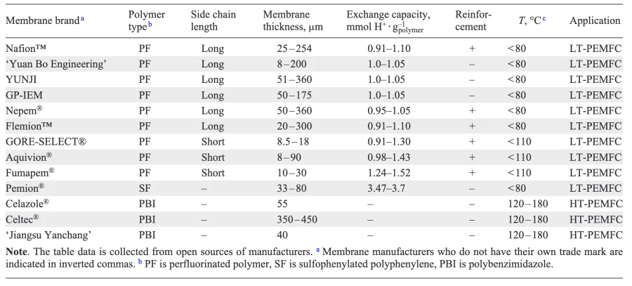
A key factor is the nature of the ionogenic groups, which can vary significantly (e.g.,–SO3–, –PO4–,–COO–, etc.). Sulfonic acid groups are strong electron acceptors with a low dissociation constant, making them the most suitable for use as functional groups in PEM, particularly in LT-PEMFCs. The main disadvantage of sulfonated polymers is that they have a narrow range of operating temperatures. This is why acid-base complexes are used as PEM in HT-PEMFCs (the polymer matrix is doped with low molecular weight inorganic acids). In addition to the synthesis of the polymer itself, the method and conditions of production of the polymer film are of great importance. The following section will provide a more detailed overview of the main types of PEM for PEMFCs.
By increasing the membrane thickness, the mechanical strength of the PEM can be improved, thereby increasing the reliability and lifetime of the PEMFC[109]. However, as the membrane thickness increases, so does its resistance[85], increasing ohmic losses in the membrane. Reducing the thickness of the PEM not only increases conductivity, but also improves water diffusion between the cathode and anode. This, in turn, together with the BPs optimization, indirectly affects the overall device size (through the design optimisation). However, if the PEM thickness is reduced too much, the mechanical properties will deteriorate and gas permeability will increase. Consequently, when reducing the thickness, it is important to ensure that the other requirements of the PEM (see Table 1) are met. Therefore, for systems where maximum specific characteristics are important and a limited lifetime is acceptable, and for PEMFCs operating under low humidity conditions, the thinnest PEMs are used. If, however, the maximum lifetime of the device is required, thicker membranes are used.
3.1.1. Membrane materials for low temperature proton exchange membrane fuel cells
PEM for LT-PEMFC is manufactured using perfluorinated polymers with side chains of varying lengths, ending in the sulfonic group (–SO3H)[110]. This type of polymer is distinguished by its exchange capacity (a quantitative estimation of the number of sulfonic groups), which is expressed in mmol of H+ per gram of polymer. The hydrophobic perfluorinated main chain of the polymer provides mechanical strength and chemical stability, while the hydrophilic sulfonated side chains promote water absorption by forming hydrated clusters. The Nafion™ membrane is most commonly used in LT-PEMFCs. It is a copolymer of tetrafluoroethylene (main chain) and perfluorovinyl ether with sulfonic acid end groups (side chain) (Figure 7a). The Nafion™ membrane, originally developed for other applications (in chlor-alkali electrolysis cells[111-113]), has an exchange capacity of 0.9 – 1.1 mmol g–1 (see Table 2) and high proton conductivity (0.13 S cm–1 at 75 °C and ambient relative humidity (RH) 100%)[96], a lifetime of more than 60 000 h (at RH > 70%, at RH < 45% the lifetime is reduced by orders of magnitude[114]) and chemical stability[96, 115]. The works[56, 67, 116-118] provide an in-depth analysis of the degradation aspects of this type of membrane. The disadvantages of Nafion-like membranes include the high production cost and the limited range of ambient RH during operation (only high values of ambient RH > 70%[14, 19, 21]).
![[{"type":"paragraph","data":{"text":"General structural formula of Nafion-like polymers with long (a) and short (b) side chain, and of the Pemion\u00ae membrane (c)."}}]](/storage/images/resized/oFweMeUGoYhYn02LbHANGjsHuZ1LxVYLVPtIC3S5_xl.webp)
The acceptable proton conductivity of Nafion-like membranes is achieved only in the hydrated state[60, 99, 119, 120], while the water content of the membranes depends on the RH of the surrounding environment[96]. At low humidity (less than 70%), the membrane dehydrates[81], resulting in a decrease in its proton conductivity and a significant increase in ohmic losses. To achieve the required specific conductivity during the PEMFC operation, the membrane must contain approximately 15 water molecules per sulfonic group[96]. It is therefore necessary to humidify the hydrogen and air supplied into the LT-PEMFC[121, 122]. It is evident that the water content of the input gases has a significant impact on the overall capacity and efficiency of the LT-PEMFC. So, it is always necessary to include a water balance control system in their design (e.g., humidification of the reagent gases, their countercurrent input into the LT-PEMFC to maximise water exchange by diffusion, or channels of a certain shape to supply gases into the BPs). In addition to humidity, the membrane conductivity and characteristics of the PEMFC are also influenced by its temperature[14, 19, 21, 81], the magnitude of the electric current flowing through the PEMFC, the flow rates and pressures of the reagent gases, and their stoichiometry[123].
To maintain proton conductivity when the humidity of the input gases decreases or when the temperature increases above 80 °C, Nafion-like membranes are modified in order to retain water and/or increase the concentration of charge carriers in the polymer. This is achieved by changing the polymer architecture, additional processing, or introducing various additives. As a result, perfluorinated membranes with short side chain lengths have been developed (Figure 7b). Such membranes are available to purchase from a number of manufacturers under various brands, including Aquivion®, GORE-SELECT® and Fumapem®. Some researchers have proposed that this type of short chain perfluorinated membranes should be considered a separate class of Aquivion-like membranes. However, this distinction is not made in this review. Due to their higher exchange capacity (up to 1.5 mmol of H+ g–1 polymer, Table 3), they have higher proton conductivity and are also able to retain water up to higher temperatures (about 110 °C) than membranes with a long side chain[76]. As a result, they are occasionally tested for use in HT-PEMFCs (for example, in the work [124]), but such a temperature is insufficient to achieve the full potential of HT-PEMFCs.
Another method of improving the proton conductivity of Nafion-like membranes is to modify them by introducing various additives (e.g., SiO2, TiO2, ZrO2, Al2O3 oxides, inorganic heteropoly compounds (e.g., Cs3–xHxPW12O40), zirconium phosphates, low molecular weight acids, ionic liquids, carbon materials or other polymers), including with subsequent additional treatment (ultrasonic, magnetic) or additional crosslinking, etc[60, 79, 99, 102, 120, 125-143].
Modification of Nafion-like membranes is also carried out in order to increase stability to HO• and HOO• radicals by doping the polymer with CeO2, MnO2, ZrO2 oxides[125, 126] and to improve mechanical properties of thin membranes by introducing reinforcing layers, including reinforcement with polytetra-fluoroethylene (PTFE). The modification can be done in a complex way, and the technology is already implemented in the PEM production. For example, perfluorinated composite reinforced membrane GORE-SELECT® with increased mechanical strength, the use of which increases the stability of PEMFC, has been developed and commercially produced[110].
The latest trend in the field of PEM for LT-PEMFCs is the development of non-perfluorinated membranes. The gradual abandonment of the use of Nafion-like membranes is driven not only by their high cost[144], but also by the complex, non-environmentally friendly method of synthesising the perfluorinated polymer. However, to date, it has not yet been possible to obtain a PEM with a ratio of characteristics (chemical stability, proton conductivity, and durability) that is better than that of Nafion-like membranes. The only promising membrane is Pemion®, which is based on sulfophenylated polyphenylene (Figure 7c)[145, 146] and is commercially available. In terms of performance, Pemion® is comparable to Nafion-like membranes[145, 146]. Nevertheless, further detailed studies of such membranes are required to fully replace perfluorinated ones.
3.1.2. Membrane materials for high temperature proton exchange membrane fuel cells
For HT-PEMFCs operating at temperatures above 120 °C, the above-described membranes are not suitable. This is because above 80 °C, there is a rapid decrease in water content, which in turn results in a reduction in proton conductivity. To avoid this, alternative polymeric membranes based on acid-base complexes are being developed to provide good conductivity at high temperatures. In recent years, there has been an increasing focus on membranes based on PBI and its functionalised derivatives, including: meta-PBI [poly(2,2'-(1,3-phenylene)5,5'-bibenz-imidazole)] (m-PBI), para-PBI [poly(2,2'-(1,4-phenylene)5,5'-bibenzimidazole)] (p-PBI), ABPBI [poly(2, 5-benzimidazole), ABPBI], PPBI [pyridine-based PBI, PyPBI], 2OH-PBI [poly-(2,2'-(2,2'-(2,5-dihydroxy-1,4-phenylene)5,5'-bibenzimid-azole)], etc. (Figure 8a)[100, 147, 148].
![[{"type":"paragraph","data":{"text":"Various types of PBI-based membrane main chain (a) 148 and example of acid-base complex based on m-PBI and phosphoric acid (b)."}}]](/storage/images/resized/yhMBp4fl2EoFS8jLz1ArSp2UeZBBkVu5XRZAfpK9_xl.webp)
The main chain of PBI polymer features a rigid aromatic group that provides a high glass transition temperature (430 °C), good chemical stability and mechanical strength. The latter is further enhanced by polymer chain modification[148-152]. However, the polymer matrix itself has low proton conductivity, with a value of approximately 10–12 S cm–1[150]. Due to the presence of a benzimidazole unit in the polymer chain, PBI has an acidity constant pKa = 5.5, which ensures the ease of its doping with strong acids such as sulfuric, nitric, hydrochloric and phosphoric acids. It is important to note that acid doping in the case of PBI actually means impregnation of the polymer matrix, while in Nafion-like membranes the molecules of the polymer matrix itself already have acid groups. The resulting acid-base complex (Figure 8b) offers high proton conductivity, regardless of the presence of water, making it suitable for use in HT-PEMFCs.
The permeability of PBI-based electrolytes is dependent on the type of acid and its concentration. It is understood The proton conductivity of the acid-doped PBI membranes under equivalent conditions is known to increase in the order of the acids used: H2SO4 > H3PO4 > HClO4 > HNO3 > HCl. Although the maximum value of proton conductivity of PBI membrane is achieved when it is doped with sulphuric acid, this is not a practical solution. This is due to the fact that the maximum conductivity of sulphuric acid is observed in aqueous solutions, and it is also a strong oxidant under the conditions of HT-PEMFC operation. It is therefore recommended that H3PO4 be used in HT-PEMFCs, as phosphoric acid-doped PBI-based membranes can to operate under anhydrous conditions due to the reaction between the acid and the N – H group of the imidazole ring (Figure 8b)[100, 147, 152]. Furthermore, H3PO4 is a weak oxidising agent, which is advantageous compared to H2SO4 for the stability of the materials used to manufacture HT-PEMFCs. Therefore, membranes based on PBI doped with phosphoric acid will be discussed next.
An important issue is the doping level (DL) of the membrane with an acid. The DL is defined as the number of acid molecules per repeating fragment of the polymer matrix, with measurements taken on the membrane mass before and after doping. The dependence of the DL of the PBI-based membrane on the concentration of phosphoric acid has a non-linear character (Figure 9)[153]. The DL of the membrane, which refers to the bound acid (as in the case of Nafion-like membranes), is constant and equal to 2, since there are two –NH groups per polymer unit. The increase in DL > 2 is due to the presence of free acid in the polymer volume[153]. As a result of acid doping, the thickness of the polymer membrane increases by 60 – 110%[100].
![[{"type":"paragraph","data":{"text":"Dependence of DL of PBI-based membrane on the concentration of phosphoric acid."}}]](/storage/images/resized/BCZXDNTAOnLjOJfZPJJfDmcMmcHOXL8iMbXJJ8Zl_xl.webp)
High proton conductivity of PBI-based membranes is only observed for materials with free acid molecules, i.e., at DL > 2. It is important to note that PBI-based membranes with different molecular weights exhibit approximately the same proton conductivity at the same DL value[154, 155]. An increase in the DL of a PBI-based membrane leads to an increase in its proton conductivity, but a decrease in its mechanical strength[89]. To enhance both proton conductivity and mechanical properties, these membranes, as well as Nafion-like membranes, are subjected to various modifications (altering the polymer backbone architecture, introducing various additives, undergoing additional treatment), enabling them to achieve proton conductivity values of 1.8 S cm–1 at 190 °C[89, 151, 154, 156-161]. While PBI-based membranes offer numerous advantages, they do have one significant drawback: the proton conductivity is provided by phosphoric acid, which can be washed out by water formed during the operation of the PEMFC. This issue is not a significant concern for HT-PEMFC, as there is no liquid-phase water present. In the case of LT-PEMFC membranes based on PBI, they are not practical due to the rapid washing out of phosphoric acid.
3.2. Materials for electrocatalysts and catalytic layers
A variety of materials are used as catalysts in ORR and HOR, including pure metals, various alloys, conducting polymers, etc. According to the complex of properties in acidic medium, the most effective catalysts are based on noble metals, with platinum demonstrating the highest activity and maximum stability[162-166]. At present, platinum-based electrocatalysts are the main materials used in PEMFCs[80, 167, 168, 162-165]. For this reason, further consideration will be given to this issue in more detail.
Due to the high price of platinum, the cost of the electrocatalyst has a significant impact on the overall cost of PEMFCs. One solution to this problem is to reduce the amount of Pt while maintaining its catalytic activity. This is achieved by using high surface area nanoparticles of Pt on a support rather than bulk metal[164]. The most common platinum supports are carbon materials with a high surface area of 100 to 2600 m2 g–1 (e.g. VULCAN® XC72 carbon black)[164, 169-172]. Such catalytic materials are defined by the quantity of electrocatalytically active metal (typically platinum) per gram of material.
There is a significant number of manufacturers of platinum-containing catalysts globally. Table 4 provides an overview of the main commercially available electrocatalysts for PEMFCs. It should be noted that the majority of these materials are used for other purposes (such as hydrogenation reaction catalysts), so they are not optimised for use in PEMFCs. The most widely available catalyst on the market is the traditional Pt/C catalyst offering a wide range of material characteristics.
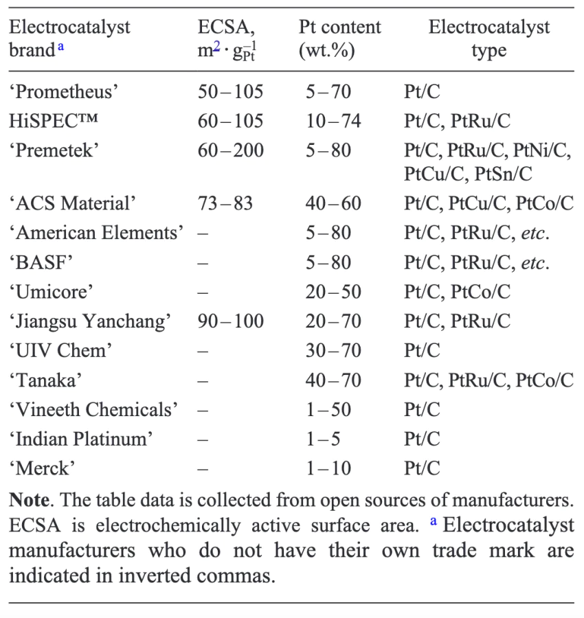
A comparison of Pt/C electrocatalysts from different manufacturers shows that at comparable platinum particle sizes and platinum content, the electrocatalysts have very close catalytic activity in PEMFC. However, their stability can vary greatly and depends largely on the type of support. Carbon materials fulfil all the requirements[86] except one — they are subject to oxidation under the conditions of TPTE operation[173].
Consequently, research is underway to explore the use of non-carbon materials as Pt supports, including transition metals, their oxides, nitrides, carbides, sulfides and their composites[165, 174, 175], which offer enhanced stability against oxidative degradation[86, 165, 174-180]. Furthermore, the specific characteristics of anodic and cathodic catalysts are being identified.
3.2.1. Catalytic layers
The catalytic layers are designed to be porous to allow the transport of reactants in the gas phase. Their electronic conductivity is provided by the catalyst support or conductive additives[127, 164]. To guarantee proton transport, a dispersion of an ionic conductor (typically similar to the membrane material) is incorporated into the catalytic layer, and hydrophobic additives are added to enhance water removal and prevent flooding of the PEMFC[43, 181-184].
The electrochemical reactions that occur in the catalytic layers of PEMFCs take place at the three-phase boundary of the solid electrolyte, the electron conductor, and the gas phase[43]. The properties of PEMFC are largely determined by the morphology of this boundary and its physical and chemical properties[37]. To achieve the maximum possible current output from the PEMFC, it is essential to ensure that the area of the three-phase boundaries is as close as possible to the theoretical value for the electrocatalyst used. To achieve this, a proton-conducting polymer similar to that used in the membrane is added to the catalytic layers. The addition of the polymer takes place at the stage of preparation of the catalytic ink (or paste) before application to the substrate. The characteristics of the three-phase interface will be significantly influenced by the composition of the catalytic ink/paste and the method and conditions of its application[185]. Figure 10 provides a scheme of the three-phase interface in catalytic layers. The efficiency of the electrocatalyst is highly dependent on the extent of the three-phase interface, which is determined by the ratio of surface area to volume.
![[{"type":"paragraph","data":{"text":"Three-phase interface in the catalytic layers of PEMFC."}}]](/storage/images/resized/Sdb8zTLr1yPNwFrLn3fpKnuYXHa4UqEMQON7wnu0_xl.webp)
The size of Pt particles affects the specific activity of the electrocatalyst and degradation processes, which are significantly accelerated with decreasing the size of Pt nanoparticles, and with increasing the operating temperature of PEMFC[186, 187]. The optimal diameter of active metal nanoparticles deposited on carbon particles is between 2 and 5 nm, with the shape of these particles also influencing the activity[120, 164, 183, 188]. Particles smaller than the optimal size (less than 1 nm) are unstable in water, which is always present in the cathode catalytic layer. As the particle size of platinum increases, its stability improves. 4 nm Pt particles are less susceptible to degradation than 2 nm particles[189]. Consequently, despite the high activity of single-atom electrocatalysts that have been studied in the literature[190-194], it is doubtful whether they will be used in practice in PEMFCs.
It is important to note that not all of the surface area of the platinum particles in the catalytic layer is available for the electrochemical reaction. For instance, part of the surface may be blocked by the support or other factors, which may prevent it from accessing the three-phase boundary. Consequently, one of the key characteristics of catalyst activity is the electrochemically active surface area (ECSA) of platinum. This is determined through experimental testing under model conditions or directly in the catalytic layer of PEMFC (in m2 gPt–1, Table 4).
One of the most important characteristics of the catalytic layer is the amount of platinum per 1 cm² of the electrode’s geometric area (catalyst content, mg cm–2). Due to simpler kinetics, the electrode polarisation for HOR is much smaller than for ORR. It is therefore standard practice to have a lower electrocatalyst content on the anode side of the PEMFC than on the cathode side. In line with DOE requirements for 2025, the platinum content on the cathode should be 0.100 mg cm–2, while on the anode it should be 0.025 mg cm–2[195]. The following section will examine the characteristics of anodic and cathodic electrocatalysts in more detail.
3.2.2. Cathodic catalysts
The ORR at the cathode is typically a slower process (exchange current density i0 ≈ 10–7 – 10–8 A cmPt–2 ) than most anodic reactions (i0 ≈ 0.01 – 0.3 A cm–2 Pt)[83, 196-198]. In essence, the energy conversion efficiency of a PEMFC is directly dependent on the kinetic challenges associated with the ORR process[199, 200]. The mechanisms of ORR on platinum include several distinct reactions with different rate constants (k) (Figure 11). Oxygen can be directly reduced to H2O with the addition of four electrons (direct ORR), but there is a risk of by-reactions, in particular the reduction of O2 by a two-electron mechanism to form hydrogen peroxide. Although the electroreduction of oxygen on platinum proceeds mainly by a four-electron mechanism, the formation of peroxide is not completely avoided. This is because the desorption stage of peroxide from the platinum surface is not electrochemical, and therefore its rate does not depend on the electrode polarisation. Consequently, the rate of peroxide formation is never equal to 0.
![[{"type":"paragraph","data":{"text":"Scheme of the mechanism of oxygen reduction on Pt catalysts."}}]](/storage/images/resized/aEx4Dt1UV9harU4OH33UQ7FDGK4plXM3w8qNQ7AK_xl.webp)
Incomplete reduction of O2 to H2O2 not only results in lower efficiency of fuel energy conversion to electricity, but also poses a risk of free OH• radicals reacting with the materials of electrode, membrane and structural components, leading to their degradation[118, 201].
At present, research is being conducted to enhance the activity of catalysts in ORR. At the same time, the logical end of reducing the size of Pt particles to achieve optimal activity has been reached, so researchers are now exploring alternative approaches. A number of research groups have proposed alternative catalysts to monoplatinum, including 1) platinum-based alloys and 2) particles with a shell of platinum and a core of less noble metal (core-shell structures)[163, 168, 183, 202-204]. The use of a core of a less noble metal allows to obtain large particles that are resistant to degradation, while consuming much less platinum. Bimetallic electrocatalysts are exemplified by Pt@Cu systems[205-209]. The oxygen adsorption energy and oxygen electroreduction kinetics of platinum alloys (e.g., PtCu, PtRu, PtCo) can vary significantly, with both positive and negative effects[204]. To date, bimetallic catalysts are less commercially widespread, but there is a wide range of options available, both in terms of composition and manufacturer.
Both approaches (alloys and core-shell structures) have a similar disadvantage: the reactivity of the alloying (additional) metal is much higher than that of platinum, so its dissolution occurs at a much higher rate. This causes the characteristics of the catalyst to change during the PEMFC operation and reduces the conductivity of the electrolyte (both the membrane and the ionomer in the catalytic layer) due to the substitution of protons for other cations. This leads to an increase in ohmic losses, which in turn causes a decrease in the power characteristics of PEMFC. Despite these drawbacks, alloy-based catalysts are already used in industry, with examples including PtCo catalysts used in PEMFCs installed in hydrogen cars[203].
As mentioned above, the cost of the platinum electrocatalyst represents a significant proportion of the total cost of the final device. In addition to reducing the platinum content in the catalyst, another method of cost reduction is the use of non-noble metals[174, 210-214] and even metal-free electro-catalysts[174, 214, 215]. These electrocatalysts exhibit reduced power characteristics compared to Pt/C materials, for example, for the Fe – N – C-based electrocatalyst, up to 480 mW cm–2[211]. To date, Pt-free electrocatalysts have not been widely used in practice due to their rapid degradation under PEMFC operation conditions[147, 214], and the low values of maximum power (2 – 4 times) compared to standard Pt/C-catalysts. This creates the need to increase the size of the PEMFC and level out their efficiency to reduce the cost of the finished device.
3.2.3. Anodic electrocatalysts
Unlike ORR, the mechanism of HOR in acidic media is simple[216] (equation (1)), which means that despite the presence of 2 – 3 reaction stages[217], the rate of HOR on platinum is several orders of magnitude higher than that of ORR[83, 196-198]. Furthermore, the intermediate products do not lead to oxidative degradation of materials. Consequently, in PEMFCs operating on pure hydrogen, a standard Pt/C catalyst with reduced loading is typically used as an anode catalyst. A number of research groups are currently engaged in the development of alternative Pt/C catalysts. It should be noted that other metals (not platinum) have less activity in HOR and less stability in acidic media. Furthermore, research is being conducted on the use of bio-anodes, but thus far, the activity in such systems is insufficient for practical application[218, 219].
The use of pure hydrogen is a significant cost factor in energy production. The use of hydrogen with a high content of impurities produced by the reforming of organic compounds can lead to a significant reduction in costs. The main impurity in this method is CO, which is a catalytic poison for platinum. The presence of carbon monoxide, even in trace amounts (10 – 100 ppm), significantly reduces the power characteristics of LT-PEMFC[38, 83, 86]. The best systems for reforming organic compounds allow the production of hydrogen with carbon monoxide admixture at the level of 10 – 60 ppm. Despite the preferential adsorption of CO on Pt, the rate of hydrogen oxidation on small remaining free areas of Pt is so high that it sets the potential at the anode. Unfortunately, this potential is below the value required for CO oxidation, and the filling of the surface with carbon monoxide is determined by the CO adsorption isotherm. HT-PEMFCs do not have this problem. As the operating temperature increases, CO begins to oxidise at potentials close to the hydrogen oxidation potential. Consequently, at 160 °C, HT-PEMFCs can operate on hydrogen with 3% CO practically without any power reduction[83], which presents an opportunity to use reformed hydrogen directly without additional purification.
Let’s take a closer look at the mechanism of CO oxidation on the platinum catalyst. The apparent activation energy of hydrogen oxidation increases with increasing CO concentration, indicating increasing difficulties for this process[220]. This may be due to the fact that CO is preferentially adsorbed on the ‘most favourable’ centers for hydrogen oxidation, or hydrogen is involved in the CO oxidation process. A number of different approaches have been employed to enhance the activity of hydrogen oxidation catalysts and improve their CO tolerance, as outlined below.
The electrochemical behaviour of CO on platinum has been the subject of extensive research for considerable period of time[221-224]. It is understood that adsorbed carbon monoxide exists on platinum in two forms — bridged and linear[225, 226]. It has been demonstrated that the electrochemical activity of these two forms is almost identical. It is postulated that the oxidation of adsorbed CO on platinum occurs via the mechanism of reaction pairs[223]. Schematically, the oxidation reaction can be written as follows:
The mechanism of CO electrooxidation includes a number of stages:
where * is the vacant adsorption site,
This process requires the presence of CO and –OH groups on neighbouring platinum atoms. However, the much higher adsorption energy of CO compared to water leads to the fact that the platinum surface at room temperature is covered with a layer of CO, and there are no free active centers for water adsorption (Figure 12a). This results in a blockage of the CO electrooxidation process at the equilibrium potential. Further details on the mechanism can be found in the works[223-225, 227-229].
![[{"type":"paragraph","data":{"text":"Schematic representation of platinum poisoning process by carbon monoxide (a) and the bifunctional mechanism of CO electrooxidation on the mixed catalysts (b)."}}]](/storage/images/resized/PflFwKzJCyciKaVRxtWBX1XCjOQR7XyTmEnHerEC_xl.webp)
At present, there are two most promising directions for further improving the properties of anode catalysts. The first is the development of nanoscale catalytic systems based on alloys of transition metals with platinum[182, 225, 230] (including single-atom catalysts), which are as effective as platinum catalysts in terms of electrocatalytic characteristics. PtRu/C catalysts are the most extensively researched and commercially available (see Table 4). However, when using non-noble metals in alloys, the same problems are encountered as with their use as the cathode electrocatalysts. Therefore, they require further development in terms of improving chemical stability in acidic media.
The second method for enhancing the catalysts is to develop highly active, corrosion-resistant and carbon monoxide-resistant catalysts by using metal-oxide nanostructured materials as a support[86, 165, 174, 176, 231]. Despite the increased number of studies on catalyst resistance to CO, the reasons for the efficiency of metal-oxide systems remain the subject of scientific dispute.
The dominant mechanism determining the stability of the catalyst to CO is considered to be the bifunctional mechanism proposed in early works[232, 233] for the bimetallic electrocatalyst PtRu and subsequently extended to other catalysts consisting of both PtM alloys (M = Sn, Mo, etc.)[234-238] and metal-oxide systems (the metal here means not only platinum but also its alloys)[165, 235, 237]. It is worth noting that the majority of metals on the surface of alloy-based catalysts in the presence of water are in the oxidised state (MOnHm) at almost all potentials[235]. This does not prevent the authors of these works from classifying such heterogeneous systems of variable composition as alloys.
The bifunctional mechanism involves the activation of water chemisorption by the base metal or its oxide and the subsequent electrooxidation of CO on the neighbouring Pt atom (Figure 12b)[206, 238]. Consequently, the removal of COads from the surface necessitates the presence of oxygen-containing groups on neighbouring sites that can oxidise the adsorbed carbon monoxide to CO2 form, thereby releasing the sites on the Pt surface for further fuel oxidation reactions. The process can be written as follows:
Another mechanism for enhancing the stability of the catalyst to CO is attributed to the electron effect (often it is erroneously referred to in the literature as the ligand effect). This mechanism is based on a change in the energy of the d-orbital of platinum, which leads to a weakening of the Pt – CO bond and, consequently, to a decrease in the blocking of HOR[239]. The interaction between Pt and CO is thought to occur in two steps[240]. Firstly, the electronic orbitals of Pt hybridise with CO orbitals, and secondly, a strong chemical bond is formed (Figure 13a). The strength of the bond formed is attributed to the presence of an empty antibonding orbital and the low energy of the bonding orbital.
![[{"type":"paragraph","data":{"text":"Scheme of platinum poisoning by CO (a) and the electronic mechanism of increasing the platinum electrocatalyst resistance to CO poisoning (b). The system erroneously referred to in the literature as \u00abligand\u00bb is highlighted by the dashed line."}}]](/storage/images/resized/FWK4HBefAJaw12yaCjWwbM8HDzCgUGBtHTNJLtyK_xl.webp)
In the case of mixed electrocatalysts, Pt atoms interact with atoms of another metal (alloy or support). This results in the Pt orbitals hybridising with increasing filling of d-orbitals[241-243]. This fills the resulting antibonding orbital and increases the energy of the bonding orbital. This leads to a decrease in the strength of the formed Pt – CO chemical bond and consequently to a decrease in the desorption energy of CO from the Pt surface (Figure 13b).
The authors of the work[244] note that the electronic structure of the catalyst is generally related to its adsorption properties. Consequently, it is possible that strengthening the bond between the catalyst and the OH group could also help the CO electrooxidation reaction via the bifunctional mechanism.
It is therefore possible that the two mechanisms of platinum resistance to CO poisoning described above may operate simultaneously. The relative contribution of each mechanism is dependent on a number of factors, including the catalyst composition, its morphology, etc[245]. In general, the electronic effect is more prevalent at low electrical voltage (less than 0.2 V) when CO adsorption is favourable, while the bifunctional effect is more pronounced at higher voltage when CO oxidation occurs[246]. It is important to note that at present, there is no ready solution for an ideal anode electrocatalyst resistant to CO poisoning at 80 °C. One solution is to increase the operating temperature of the LT-PEMFC, which is currently limited by the proton conducting properties of the PEM.
3.3. Gas diffusion layer materials
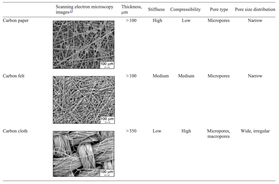
The GDLs are porous electron-conducting materials. Carbon-based materials are the most commonly used in PEMFCs, which are mainly in the form of carbon paper (nonwoven material) and carbon cloth (woven material), and less frequently carbon felts or aerogels[25, 35, 36, 64, 247-251]. In addition to carbon, metal-based foamed materials (steel, titanium, etc.) can also be used for the manufacture of the GDLs[36, 63, 249]. However, due to the fact that such GDLs have high contact resistance with carbon materials, high weight and tendency to oxidise, and the ability to poison the PEM with metal ions, we will not consider them in this review. Nevertheless, there is a potential for such metal GDSs to find an application in the future due to their high thermal conductivity. The porous structure, high electrical conductivity and thermal conductivity of carbon materials meet the conditions and requirements of the PEMFC operation (see Table 1). Furthermore, their manufacturing technology is relatively advanced, which greatly simplifies the production process.
Carbon GDLs are commercially available in a variety of properties and with a wide range of treatments for different environments[36, 67, 249, 252]. Carbon GDLs are manufactured using three distinct production techniques, namely paper, cloth and felt[36]. Carbon paper is produced by impregnating carbon fibres with a thermosetting resin. After the impregnation process, the carbon fibres are graphitised at temperatures above 2000 °C to achieve optimal electrical conductivity and mechanical properties. In carbon cloth, the carbon fibres are woven, eliminating the necessity for a binder. In the production of carbon fabric, graphitisation occurs after the spinning and weaving of the carbon yarns. In the felting process, the finished carbon felt is chopped into short pieces and mixed with a binder before undergoing graphitisation.
Due to the differing manufacturing methods used to produce the carbon GDLs, these materials exhibit varying structures and properties (stiffness, compressibility, porosity and roughness). This results in different performance under diverse conditions and PEMFC designs (Table 5). Consequently, the stiffness of the material increases in the following order: cloth < felt < paper. Higher stiffness provides greater stability of the porous structure under compression, but it is less convenient for mass production of PEMFCs by roll technology. Greater compressibility can also be an advantage, as it can compensate for dimensional changes during the PEMFC operation due to pressure and temperature changes, and the membrane swelling caused by hydration (or acid filling)[36, 249]. For instance, the carbon cloth, due to its high compressibility, can penetrate the channels of the BP (this is particularly noticeable for channel widths above 1 mm), preventing the transport of the reagent gases. This has a negative impact on the performance of PEMFC. Consequently, when the channels are sufficiently wide (approximately 3 mm), it is advisable to use a stiffer carbon paper over the carbon cloth[253].
Most of the research has focused on studying the GDL for the cathode side of PEMFCs, given its critical role in maintaining the water balance[254]. Based on experimental and calculated data, many researchers agree that at high humidity of the input gases (60 – 100%), the carbon cloth shows better performance at high current densities (> 800 mA cm–2), while the carbon paper performs better at lower current densities (< 800 mA cm–2)[36, 249]. The higher porosity and larger pore size of carbon cloth were identified as the primary factor contributing to the improved performance at higher current densities. The larger pores formed by the fibre weaves in the carbon cloth allow liquid-phase water to concentrate more effectively than in the paper, and this water is efficiently drained into the BP channel. Concurrently, oxygen can permeate the smaller pores within the cloth fibre bundles[249]. Therefore, under 100% humidity conditions of the input gases and at high current densities (> 800 mA cm–2), where concentration polarisation plays a dominant role due to the oxygen concentration gradient, the carbon cloth offers superior performance. It is also important to note that due to the higher compressibility of carbon cloth, the final porosity in the assembled PEMFC must be considered and compared. The carbon paper, due to its highly tortuous structure, retains more water than the carbon cloth, especially under the stiffening ribs of the BPs[255], resulting in a lower oxygen concentration in the carbon paper compared to the carbon cloth. This is particularly important in low humidity conditions (below 45%) when membrane hydration is limited. The use of carbon paper, which exhibits superior water retention, enables the enhancement of PEMFC power characteristics.
To maintain the water balance and enhance the performance of PEMFC, the GDL is further modified, for instance, by increasing its hydrophobicity to cope with water flooding of the catalytic layers. To achieve this, the GDL is typically treated with hydrophobic agents such as PTFE or fluorinated polyethylene propylene. The addition of PTFE in an amount greater than optimal for the specific device conditions results in reduced porosity and partial insulation of the conductive material by PTFE. This in turn can inhibit the reagent transport and negatively affect the bulk conductivity and contact resistance of the GDL[256]. As noted in the work[257], the impact of wettability on the water distribution control and PEMFC performance is more indirect than the effect of the GDL porosity. A potential solution to enhance oxygen diffusion in highly hydrophobised GDL is to introduce perforations in the GDL layer[258]. It is particularly important to consider additional hydrophobisation when the PEMFC is operating at low temperatures where water evaporation is low.
Another modification of the GDL is the application of a microporous layer (MPL) consisting of carbon black and PTFE. The addition of one or more MPLs to the GDL backbone is primarily intended to[249, 250, 255, 259-261]:
— improve mass transfer of the reagents,
— maintain water balance to avoid flooding of the GDL,
— reduce contact resistance between the catalytic layer and the GDL,
— stabilise the catalytic layer against penetration into the GDL volume.
The use of MPL also ensures the membrane hydration in conditions of decreasing humidity due to the formation of a hydraulic barrier by the hydrophobic MPL (water accumulated in the catalytic layer must reach a higher pressure to enter the pores of the MPL). At higher humidity levels, the MPL enhances and stabilises the removal of water from the MEA, thereby increasing the efficiency of PEMFC[262].
The market offers a wide range of commercially available GDLs with varying properties and treatments for different operating conditions. Table 6 provides a comprehensive overview of the currently available GDLs. It is evident that all three carbon GDL production technologies are equally common among manufacturers, given their respective advantages and disadvantages. Additionally, it is noteworthy that all major manufacturers use both types of the GDL modifications in their products.
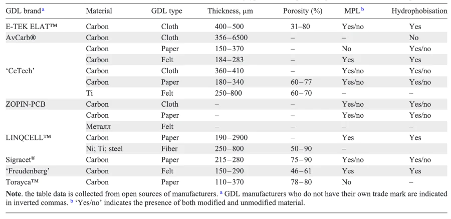
It should be noted that the industry optimises only GDLs manufactured using the felt and paper technology, which indicates that they are more suitable for use in the composition of LT-PEMFCs. All major manufacturers of the carbon papers offer a comprehensive range of the GDLs optimised for PEMFCs, suitable for use in a wide range of conditions. At the same time, GDLs from different manufacturers, optimised for operation in the same conditions (for example, as part of the PEMFC for transport), provide similar performance characteristics of the device[36, 67, 249, 252]. The primary objective in the production of GDLs is to enhance availability, which in turn reduces cost.
3.4. Bipolar plate materials
Like other PEMFC components, BPs are produced on an industrial scale. The BP is as important a component of the PEMFC as the MEA. Each individual MEA is capable of producing less than 1 V under typical operating conditions, which is insufficient for most applications. Therefore, in practice, FCS is used — a stack of MEAs separated by BPs, which provide electrical conductivity between MEAs and physical strength to the assembly. The channels available on the surface of the BPs allow for the flow of gases through the MEAs. Additional channels within the BPs can be used to circulate liquid coolant, as the BPs play a key role in the heat transfer process within the PEMFC. Therefore, in addition to the requirements listed in Table 1, the materials of the BPs must be easy to machine. A significant number of studies have been conducted on the design of the internal channels of BPs[66, 263-269].
Over the past 15 years, the requirements for PEMFC components have been refined. This has involved raising and lowering some component property requirements due to a rethinking of factors affecting the performance of FCSs during operation. For instance, in accordance with the DOE’s 2020 requirements, a number of the BP characteristics were already achieved in 2015, including the anodic and cathodic corrosion current parameters, the electrical conductivity, and the specific contact resistance[68, 69]. Currently, the BPs account for up to 80% of the weight of PEMFC, up to 50% of its volume and up to 40% of its cost, which presents a significant challenge to the large-scale commercialisation of PEMFCs[68, 270]. Therefore, the cost of BPs must be reduced by a factor of 3.5 by 2025, which is one of the most challenging tasks[69]. It is also important to note that the cost of metal accounts for approximately half of the cost of BP, which makes it impossible to achieve the targets without a multiple increase in the specific power of the device.
BPs are manufactured using a variety of materials, including carbon, composite materials, and various metals[67, 68, 271-273]. The following section will consider the advantages, disadvantages and production technology of the three aforementioned types of BPs.
3.4.1. Composite bipolar plates
A composite material is a material containing corrosion resistant polymeric materials and conductive fillers. Both thermoset and thermoplastic polymers (e.g. polyvinylidene fluoride, polypropylene, etc.) can be used as polymeric materials for the BPs[274-277]. Thermoset materials are much more commonly used than thermoplastics[71]. The main disadvantage of these materials is their low electronic conductivity. When incorporating conductive fillers such as metals or carbon materials, it is crucial to consider the impact on the mechanical properties of the resulting material.
Much of the research into BP-based composite systems has focused on carbon materials as fillers due to their low density and wide availability[68, 70, 71, 278]. Metal particles have higher electrical conductivity compared to carbon fillers, but they have higher density and are prone to corrosion under PEMFC operating conditions[69].
Typically, composite BPs are manufactured by compression or injection moulding, which allows the gas flow channels to be formed immediately, eliminating the costly machining stage[279]. The advantages of this type of BPs are: high corrosion resistance, low volume and weight, high compressive strength; and the disadvantages are: low flexural strength, low electrical conductivity, difficulty for mass production, high cost.
3.4.2. Non-porous graphite bipolar plates
Non-porous graphite BPs are typically manufactured by graphitising a blend of carbon/graphite powder and graphite resin at high temperature. The graphitising temperature is usually in excess of 2000 °C. This process must be carried out at a low rate of temperature rise, and therefore takes a long time. Furthermore, during the graphitisation process, the evaporation of impurities can create new voids, resulting in 20 – 30% porosity on the surface of the graphite plates[69]. This can lead to the reagent leakage, reducing the power and efficiency of the PEMFC. Consequently, to reduce porosity and enhance surface quality, graphite plates require further processing (e.g. impregnation with sodium silicate solution [71]), which increases their cost. Compared to other types of BPs, graphite plates are more susceptible to damage during the manufacturing process. Due to their low strength and brittleness, graphite BPs are not suitable for forming ultra-thin plates (<1.5 mm), which increases the mass and dimensional characteristics of the manufactured PEMFC[278].
Graphite BPs offer a number of advantages, including excellent corrosion resistance, high thermal and electrical conductivity, and a sufficiently developed production technology. However, they also have a number of disadvantages, including poor mechanical properties (brittleness), high weight (due to the need to manufacture thick graphite BPs), poor machinability, and a high cost of processing. The high cost and mass-dimensional characteristics of this type of BP make it unsuitable for use in PEMFCs with high specific characteristics and low cost. However, the homogeneity of the material and high corrosion resistance allow it to be used in stationary devices where a very long lifetime (more than 30 000 hours) is required[71].
3.4.3. Metal bipolar plates
Metallic materials (stainless steel, titanium, aluminium, nickel) are attractive due to their mechanical properties, high thermal and electrical conductivity, wide choice of alloys and the possibility of manufacturing ultra-thin BPs (<1 mm)[280, 281]. However, such metals are susceptible to corrosion in PEMFC operation conditions due to the presence of acidic environments and humidity. Dissolved ions can poison the membrane and the catalyst, reducing the power of the PEMFC[282]. Furthermore, the natural oxide film on the surface of the metals increases the contact resistance between the BP and the GDL, thereby impairing electron and heat transfer, ion transport through the polymer membrane, and hence the efficiency of the PEMFC[283].
To prevent the formation of oxides and contamination of the membrane and the catalytic layer with the metal ions, the BP surface is coated with a corrosion-resistant coating with a coefficient of thermal expansion close to that of the base metal of the BP. This is to avoid fracture when the operating temperature of the PEMFC changes. Carbon or polymeric materials, noble metals, metal nitrides and carbides can be used as protective coatings[280, 284-289]. It is important to note that the majority of the coatings proposed in the literature for BPs meet the DOE requirements for corrosion current and contact resistance. Furthermore, they can also contribute to reducing the cost of BPs in mass production[286].
In general, metallic BPs offer the following advantages: high thermal and electrical conductivity, excellent mechanical properties, ease of fabrication, low cost, excellent resistance to shock and vibration, and the ability to fabricate ultra-thin BPs (and thus lighter than graphite BPs). A disadvantage is the need to apply a protective coating to fulfill the requirements for contact resistance and corrosion resistance (this is an additional production stage, increasing the cost of the finished device).
The significant advantages and relatively few disadvantages of metal BPs are driving their replacement of carbon and composite BPs in the market. However, due to the protective coating on the surface of the BPs, the guaranteed lifetime of such BPs < 10 000 h (sufficient for mobile devices) is insufficient for stationary applications.
As a result, the commercial production of key components of PEMFC (membranes, electrocatalysts, GDL and BP) has been established on a global scale. At the same time, all materials are available in several variants, which can differ quite significantly in their properties. However, to date, there is no universal component that meets all the requirements for all types of PEMFCs. Consequently, despite the wide range of materials currently available for PEMFCs, further research and development is required to enhance the performance of all the key materials to ensure that they operate effectively under the diverse conditions encountered in commercial devices.
4. Influence of material properties and various factors on current-voltage characteristics, efficiency and power of proton exchange membrane fuel cell
As mentioned above, the efficiency of the PEMFC is defined as the ratio of the electrical voltage at which the PEMFC operates to the theoretical voltage at open circuit and at a given temperature. As the electrical current of the PEMFC increases, the electrical voltage losses increase, so the maximum efficiency of the PEMFC is achieved at the minimum current. The maximum power of the PEMFC often lies in the area of low efficiency values (25 – 30%)[290] (see Figure 3), so most often the focus is placed on the optimal power level at acceptable efficiency. The performance of the PEMFC is influenced by a number of factors: from the material of the components to the operating conditions[51, 291-293] e.g. the water balance of the system (for which different techniques are developed)[294], even the assembly pressure of the MEA[295, 296]. This section will discuss the main material properties and factors affecting PEMFC performance in more detail.
4.1. Proton exchange membrane resistance
The power characteristics of the PEMFC are primarily influenced by the internal resistance of the device, one of the components of which is the resistance of the PEM. The electrical resistance of the membrane, in turn, depends on its composition (membrane material and additional modifications), thickness, and ambient temperature and humidity[48, 96, 99, 297-302]. As mentioned earlier, the membrane determines the operating temperature range of the PEMFC[81, 96, 303]. With increasing membrane thickness and water content, its mechanical strength increases and the crossover of reagent gases decreases[304-307]. As the thickness of the PEM increases, its electrical resistance also increases, which in turn leads to a decrease in operating currents. For example, the electrical current of the LT-PEMFC at 0.5 V decreases in the following order of PEM materials: Nafion™112 (50 mm thickness, 1041 mA cm–2) > Nafion™115 (125 mm thickness, 736 mA cm–2) > Nafion™117 (175 mm thickness, 722 mA cm–2). In practice, even thinner membranes of 25 and 10 mm are often used. Some calculations indicate that the optimal membrane thickness is between 20 and 60 mm[17, 290, 308], as they are better wetted but may have increased hydrogen crossover[309].
4.2. Catalytic layer properties
The catalytic layer represents the most complex aspect in terms of its influence on the power and lifetime characteristics of the PEMFC. The influence of the main factors is presented in Figure 14. It should be noted that the list is not exhaustive.
![[{"type":"paragraph","data":{"text":"The main factors influencing the performance of PEMFC catalytic layers."}}]](/storage/images/resized/Xf5kDW46cE3EeWOofCQZFkdLSSE3epjiOOeFwfJK_xl.webp)
The performance of the PEMFC is influenced by the electrocatalyst activity and various voltage losses. The primary objective of research in this field is to reduce the platinum content while maintaining high PEMFC performance. In the 1980s, the most significant advancement was the applying of nanoscale platinum particles on a carbon support, which reduced the platinum content in the catalytic layer by 10 times to 0.4 mgPt cm–2 while maintaining the power characteristics of the PEMFC[310, 311]. In most cases, a platinum content of 0.4 – 2 mgPt cm–2 is used. Further research has been conducted on even lower Pt contents (~0.1 mgPt cm–2) to meet DOE requirements for the amount of catalyst on the cathode (Table 1)[37, 312-314]. In the work[314], the catalyst content was varied at a fixed thickness of the catalytic layers (Figure 15)[314]. The results demonstrated that under the experimental conditions, a significant (more than twofold) increase in the specific power of the PEMFC was observed when the Pt content was increased from 0.025 to 0.1 mgPt cm–2. However, further increases in the platinum content of the electrocatalyst had minimal impact on the P value. Therefore, it is not cost-effective to increase the platinum content excessively in the catalytic layer[314].
![[{"type":"paragraph","data":{"text":"Dependence of specific power of PEMFC on Pt content in the catalytic layer at 0.65 V (input gas humidity is 100%, 80 \u00b0C, 150 kPa)."}}]](/storage/images/resized/hAI0d80uSJnUP1b02U1SWCvUd8aUbqqDcbylrCWH_xl.webp)
In addition to power performance, the catalyst content also has an impact on the cost of PEMFC. The contribution of catalyst to the cost of a PEMFC is estimated to range from 21% for production of 1000 units per year to 45% for production of more than 500 000 units per year[311, 314]. Accordingly, the DOE has set a target for the catalyst content of PEMFC anode of 0.025 mgPt cm–2 (although some work reported lower values [315]). The target for the Pt content of the cathode is higher, 0.100 mgPt cm–2, but an even the lower content of 0.0625 mgPt cm–2 is required for PEMFC cars to match the cost of ICE cars[286]. However, as shown above, the lower Pt content leads to the lower power performance, necessitating the use of highly active catalysts to maintain the acceptable PEMFC power levels. PEMFC power characteristics for different Pt contents in the catalytic layers are shown in Table 7 and Table 8. It should be noted that the evaluation of the influence of each catalyst on the power characteristics is problematic due to the fact that the measurements were carried out under different conditions and with different components of PEMFC. In the case of LT-PEMFC, high power can be achieved at low electrocatalyst contents (even below the DOE target of 0.125 mgPt cm–2)[313], while HT-PEMFC has very low power (insufficient for successful application) at low platinum contents.
![Power characteristics of LT-PEMFC at 0.6 V, Pt content in catalytic layers and type of electrocatalyst (Pt content in wt.%), membrane brand, operating temperature (T), ambient humidity (RH), air (λO2) and hydrogen (λH2) stoichiometry, hydrogen (p(H2)) and air (p(air)) pressure. Refs. [<a class="anchor" href="#reference-1903">145</a>, <a class="anchor" href="#reference-2050">292</a>, <a class="anchor" href="#reference-2071">314</a>, <a class="anchor" href="#reference-2073" id="mention-reference-2073">316</a>-<a class="anchor" href="#reference-2082" id="mention-reference-2082">325</a>]](/storage/images/resized/kiGgIpTlgG6kk4NajCEBxlTfFmDXeRlrgWjDZXr4_xl.webp)
![Power characteristics of HT-PEMFC at 0.6 V, Pt content in catalytic layers and type of electrocatalyst (Pt content in wt.%), membrane brand, operating temperature (T ), ambient humidity (RH), air (λO2) and hydrogen (λH2) stoichiometry, hydrogen (p(H2)) and air (p(air)) pressure. Refs. [<a class="anchor" href="#reference-1848">90</a>, <a class="anchor" href="#reference-2083" id="mention-reference-2083">326</a>-<a class="anchor" href="#reference-2095" id="mention-reference-2095">338</a>]](/storage/images/resized/V5gsOmFfUscw5Dt3KPqPyB1KIDfKndBwauZjLVNI_xl.webp)
To enhance the specific activity of the catalysts, they are manufactured with a low Pt content (below 20 wt.%)[339]. This requires an increase in the thickness of the catalytic layers to achieve the required activity, which, in turn, limits mass transfer. A reduction in the thickness of the catalytic layer improves the performance of the PEMFC in all three current density ranges (see Figure 3b). This is due to the high electrocatalyst activity resulting from the large platinum surface area, the low proton transfer resistance in the catalytic layers, and the higher efficiency of O2 molecules to reach the Pt surface on the cathode side[340, 341]. As the platinum content in the catalyst increases, its activity per unit mass of Pt decreases, but the conductivity of the catalytic layer increases and diffusion losses decrease. Consequently, the optimal platinum content in the catalyst is determined by the balance of these properties and can range from 40 to 80 wt.%, depending on the type of PEMFC and its operational conditions[341]. The calculated optimum thickness of the catalytic layer is 10 – 40 mm[17, 311].
One of the most important factors is the catalyst lifetime, which is directly influenced by the size of the platinum particles. Larger platinum particles are less susceptible to degradation[189]. In addition, a high platinum content in the catalytic layers is used to extend the lifetime of PEMFCs (reducing the degradation of the catalytic layer). This is particularly evident in HT-PEMFCs, where degradation processes are accelerated due to the higher operating temperature. Consequently, it is often necessary to use a catalytic layer with a high platinum content (1 – 2 mgPt cm–2), which is well above the DOE targets even for 2020 (0.125 mgPt cm–2)[314].
In addition to the platinum content, the other components of the catalytic layer also affect the performance of the PEMFC: the type and content of the ionomer, the type of platinum support, the type of solvent used to prepare the catalytic ink, the method of preparation and application of the catalytic layer, including the application of several catalytic layers with different platinum contents or the application of the catalytic layer on the membrane instead of the GDL[260, 293, 312, 313, 342-348]. For instance, there are developments in the production of ultra-thin catalytic layers (1 μm) due to the absence of ionomer, which allows for an increase in the active surface area of platinum and a reduction in the content of noble metals[347] or the complete elimination of their use[348]. However, such technologies are unlikely to be widely adopted in the near future due to the increased degradation rate of ultrathin layers and the lower specific capacity of the PEMFCs with non-platinum catalysts.
4.3. Gas diffusion layer properties
The operating mode and structure of the PEMFC (gas humidity, operating temperature and current magnitude, channel dimensions, etc.) require the selection of an optimised GDL[36, 249, 349]:
— woven GDL is used for high current densities (>800 mA cm–2) and high humidity of the input gases, but it cannot be used for wide channels in the BPs,
— non-woven GDL is better suited for dry operating conditions and any channels in the BPs,
— hydrophobisation is required for high humidity of the input gases (>70%) to avoid the cathode flooding,
— MPL improves the PEMFC performance in all conditions.
By varying the composition of the MPL and applying several functional layers to the carbon paper, we have achieved a specific PEMFC power of more than 1 W cm–2[350, 351]. The authors of the works[352-354] have demonstrated that MPL can boost the power of a PEMFC by up to two times at 0.6 V, depending on the measurement parameters. The high roughness of the GDL due to the MPL applied can have a negative impact on the PEMFC power characteristics in the case of non-uniform or insufficient pressing due to the increase in contact resistance[260],. A reduction in porosity and an increase in the thickness of the GDL (Figure 16)[355], and the formation of cracks[356] during the pressing of the MEA or in harsh operating conditions, can lead to a decline in the power characteristics. Consequently, a significant number of studies are focused on the mechanical properties of the GDL[64, 357].
![[{"type":"paragraph","data":{"text":"Dependences of the HT-PEMFC specific power (0.4 V, 180 \u00b0C) on thickness and porosity of the GDL."}}]](/storage/images/resized/zvY7auMTOmo3ragrQux2I4A6whLJGB2lemjaPa4X_xl.webp)
4.4. Operating temperature
The performance of a PEMFC is significantly affected by the operating temperature (Figure 17)[358, 359]. This is due to the fact that the rate of electrochemical reactions, the rate of mass transfer, and the membrane conductivity increase with temperature. The operating temperature is a function of the properties of the materials used, and its selection must consider the hydration level of the membrane. It should be noted that during operation, a PEMFC heats up due to voltage drop across its various elements (see Chapter 2). Additionally, heat distribution in both the single MEA and the FCS is non-uniform[25]. At low current densities, the main heat generation is in the catalytic layer due to activation polarization. However, as current density increases, the contribution of Joule heating increases due to the increased contribution of ohmic polarization[360].
![[{"type":"paragraph","data":{"text":"LT-PEMFC specific power vs. temperature with different brands of Nafion\u2122 membrane (0.5 V, humidity of the input gases is indicated in the legend in %)."}}]](/storage/images/resized/LvdxyJaKQqrM3sVyArU5xUD9zfqk7lB7rS8ojTbo_xl.webp)
Under conditions of symmetric humidification of the reagent gases, operation of the LT-PEMFC at temperatures of ~70 – 80 °C leads to an improvement in power characteristics. This is due to an improvement in mass transfer, an increase in the diffusion coefficient in boundary layers and the membrane, a decrease in membrane resistance and an increase in the electrocatalytic activity of both electrodes. At the same time, there is an optimal humidity of the input gases, the value of which depends on the current density. However, further increases in temperature have a negative impact on the PEMFC performance due to a reduction in the membrane water content as a result of increased evaporation[88, 292, 304, 361, 362]. An increase in operating temperature should be accompanied by an increase in hydrogen humidity (to avoid a loss of performance)[363] or an increase in current density up to 400 mA cm–2 (to self-humidify the membrane)[317]. At low temperatures (below 60 °C), the PEMFCs is susceptible to cathode flooding, which can lead to oxygen deficiency and a reduction in the device performance[317, 362].
HT-PEMFCs are operated at temperatures above 100 °C to prevent condensation of water, which can wash out phosphoric acid from the membrane. For HT-PEMFCs, there is also a well-defined temperature dependence of the performance characteristics (Figure 18)[17, 74, 149]. However, it is important to note that the applied temperature is also a critical parameter. While the performance characteristics increase with increasing temperature, the durability of the PEMFC decreases rapidly with increasing temperature. It is therefore essential that the temperature within the FCS is maintained a consistent level and that it is not exceeded, as this can have a detrimental impact on the device and its components. Whit regard to the expected lifetime, various authors have identified 160 – 180 °C as the optimum operating temperature for HT-PEMFCs[74, 364, 365].
![[{"type":"paragraph","data":{"text":"Dependence of the specific power of the HT-PEMFC on the operating temperature (0.65 V, BASF Celtec P2100 MEA membrane)."}}]](/storage/images/resized/97SOfbWUXqGjqdpLOo3SF3CnzHJZV5vfEZa4QRni_xl.webp)
4.5. Temperature and humidity of input gases
As mentioned above, the electrical conductivity of the membrane is significantly influenced by its hydration level and the operating temperature. To ensure a high water content of the polymer electrolyte, it is essential to humidify the gases supplied into the PEMFC[366-368]. To extend the lifetime of the FCS, it is essential to ensure uniform membrane humidification over its plane. It is important to prevent the formation of dry areas as this can affect the uniformity of current distribution, which in turn will have an adverse effect on the PEMFC lifetime[369]. Furthermore, it is important to avoid the PEM swelling-drying cycles, as this can cause a change in size and further delamination from the catalytic/gas diffusion layer[123]. Increased gas humidity can raise the operating temperature of the PEMFC, which has a positive effect on reaction kinetics[370]. For example, when the humidity of the gases supplied to the PEMFC is simultaneously reduced from 100% to 25 – 30%, the specific power of the PEMFC with the Nafion™ membrane decreases by a factor of 3 – 4 due to increased activation and ohmic losses (Figure 19)[49, 358, 368, 371, 372].
![[{"type":"paragraph","data":{"text":"Dependence of the PEMFC specific power on the water content of the input gases at 0.6 V, 85 \u00b0C, \\( \\lambda_{\\mathrm{O}_2} = 4 \\), \\( \\lambda_{\\mathrm{H}_2} = 1.2 \\)."}}]](/storage/images/resized/xZJfXnRKrsIA0OSMBjQ3uAoRzemArtBJTFrkRm3i_xl.webp)
If simultaneous humidification of the cathode and the anode is not an economically viable option, it is necessary to determine which of the gases will be humidified. In the case of asymmetric humidification of hydrogen and air, it is crucial to determine which of the gases is supplied into the PEMFC in the dry state. The majority of researchers agree that air (cathode) humidification has a greater effect on PEMFC performance than hydrogen (anode) humidification, and that an acceptable performance can be achieved by reverse diffusion of water to the anode[48, 292, 359, 361, 366, 368, 372-375]. Some calculations indicate that hydrogen humidification has a greater effect on PEMFC performance[41, 291, 376]. Hydrogen humidification is also an acceptable method, in which case water flows to the cathode together with protons due to electro-osmotic movement. In the presence of current, reverse diffusion of water from the cathode to the anode under a pressure gradient is a more effective method of maintaining operating conditions than electroosmosis of water from the anode to the cathode. At medium to high levels of input air humidity (>45%), reverse diffusion of water is sufficient to maintain the membrane hydration, and further hydrogen humidification does not result in a significant improvement in performance. The lower humidity of the cathode side compared to the anode side in PEMFCs is necessary to maintain the water content of the membrane at high current densities due to the formation of large amounts of water[41]. At high current densities (>800 mA cm–2), there is a degree of self-humidifying of the membrane with the formed water[361]. Therefore, the type of asymmetric humidification depends on the operating parameters of the device. In any case, to reduce the influence of humidity on the PEMFC operation, the humidification retention capacity of the PEM can be increased, for example by modification as described in Chapter 3.
Similar studies for the FCS have shown that an increase in the gas humidity leads to an improvement in its voltammetric characteristics (Figure 20)[377]. The maximum power is achieved at symmetric gas humidification over 60%[375, 377-379]. At this humidity, the distribution of voltages across the MEA of the FCS is more uniform.
![[{"type":"paragraph","data":{"text":"Dependence of the FCS specific power on air humidity at different hydrogen humidity (0.71 V, 70 \u00b0C)."}}]](/storage/images/resized/QCyEe12Nl5glab2sJSPGOZsV5lTYzoRp1R01yqiO_xl.webp)
It is evident that the optimal values of relative humidity of gases supplied to the cathode and the anode vary and depend on the conditions of thermal control, gas flow rate, and current density[368, 380-383]. For instance, the authors of the work[384] provide the precise value of the optimal gas humidity, which is 70%. However, in order to optimise the PEMFC power characteristics, a number of other specifications must also be defined. It is therefore evident that another crucial parameter affecting the characteristics of PEMFCs is the temperature of the input gases at the inlet of the device. As the humidity of the gases decreases, the effect of the gas temperature increases[371]. In the work[359] it was demonstrated that lowering the temperature of fully humidified gases supplied into the PEMFC below the operating temperature of the device itself (from 80 to 50 °C) results in a decrease in the specific power from 488 to 130 mW cm–2 at 0.6 V. This behaviour can be explained by the improved reaction kinetics and ionic conductivity at higher temperatures. With an overall operating temperature set at 80 °C in all cases, lowering the temperature of the input reagent gas below 80 °C has the effect of cooling the element and reducing the humidification of the PEMFC (e.g., the vapour pressure of water at 100% input gas humidity and its temperature of 50 °C corresponds to an input gas humidity of 26% at its temperature of 80 °C). This results in a reduction in the ionic conductivity of the electrolyte, an increase in ohmic losses and an uneven humidifying of the membrane, which has a detrimental impact on the lifetime of the PEMFC. It is therefore desirable to heat the input gases to the operating temperature of the PEMFC.
4.6. Gas pressure and stoichiometry
The performance of the PEMFC is significantly influenced by the pressure of input oxygen (air)[80, 385]. As the pressure increases, the power performance improves due to enhanced mass transfer and elevated rates of electrochemical reactions (1) and (2), which are directly proportional to the partial pressure of hydrogen and oxygen (Figure 21)[385-387]. The most commonly used pressure range is 1 to 2.5 atm[52, 376, 388]. It is observed that an improvement in PEMFC performance is achieved when the pressure at the cathode is increased in comparison to the anode[389]. However, in order to maintain the membrane durability, it is important to ensure that the pressure difference does not exceed 0.5 atm[41, 48]. The performance of the PEMFC can be increased by pulsing the gas pressure, which optimises the gas convection process[41]. As the exhaust air pressure at the outlet of the PEMFC is higher than atmospheric pressure (exhaust air cannot spontaneously vent to the atmosphere if its pressure is lower than atmospheric pressure), the turbines can be used for energy recovery, recovering up to 80% of the energy used by the compressor. It should be noted that increasing the pressure of the gases supplied to the PEMFC requires better sealing and the use of additional devices (compressors) to operate the device, which will be discussed in more detail below. In addition to pressure, the stoichiometry of the input gases (λ) has a significant impact on the power characteristics of the PEMFC. For instance, for PEMFCs with closed cathode (will be discussed below), the optimal gas stoichiometry (λopt) is approximately 2 (Figure 22)[35, 309, 388, 390, 391]. When λ is below the optimal value, the voltage loss associated with concentration polarisation increases due to the low water removal rate and lower oxygen concentration. When λ > λopt due to excessive air flow, water removal is intense, leading to a decrease in the proton conductivity of the membrane and an increase in the ohmic voltage losses of the PEMFC, in addition, the power consumption of the compressor increases significantly.
![[{"type":"paragraph","data":{"text":"Dependence of the PEMFC specific power on air pressure (0.6 V, 80 \u00b0C, \\( \\lambda_{\\mathrm{O}_2} = \\lambda_{\\mathrm{H}_2} = 2 \\), input gas humidity is 100%)."}}]](/storage/images/resized/CFWX0EFjR0vz2EX4kH2SgsyfFVBLEmFdP9N9jXqG_xl.webp)
The authors of the work[52] optimised the performance of a 30 kW PEMFC system by optimising the air pressure and λ at electrical loads of 100 – 250 A: the optimum gas pressure for maximum power is always in the region of lower values (1 – 2 atm), and λopt tends to increase gradually as the current increases. Based on the above, to maximise the efficiency of the PEMFC, an air compressor with an output pressure of up to 2.5 atm should be selected and λ should be varied depending on the current load. Excessive air flow rates can lead to water removal, which in turn causes the membrane to dry out and increase its electrical resistance[292].
In summary, the PEMFC is a complex system with components that interact each other. External factors (operating conditions) also have a significant influence on the characteristics of the components and, consequently, on the power characteristics of the manufactured PEMFC. This must always be taken into account when creating and optimising such systems. In addition, the air supply method and the type of cooling system influence the performance of the PEMFC. Due to the significant impact these factors have on the design, they are discussed in a separate chapter.
5. Methods of cooling and air supply in proton exchange membrane fuel cells
The PEMFC generates electricity with simultaneous heat generation during the electrochemical reactions (1) and (2). The local and overall distribution of current density associated with the reagent feed rate directly affects the temperature distribution inside the FCS, and hence the electrochemical reaction rate (the electrochemical reaction rate increases with temperature) and the performance of the PEMFC.
In PEMFCs, the amount of heat generated during operation is 45 – 60% of the total energy produced during hydrogen oxidation (Figure 23)[25, 273, 392, 393]. This heat can be removed from the PEMFC in various ways, e.g. with excess of the reagents, evaporation of water formed, convection from the external surface of the PEMFC. However, these methods of heat removal are inefficient and do not allow to achieve the high values of specific power of PEMFC. Consequently, all modern PEMFCs are equipped with an additional cooling system that removes up to 85% of the heat generated.
In LT-PEMFCs, temperature affects the water content of the PEM, which in turn affects the membrane conductivity. If the temperature is too high, the membrane loses water, causing increased membrane brittleness, which can lead to irreversible power loss. At low temperature, flooding of the cathode channels in the BP can occur, leading to difficulties in oxygen transport through the GDL. In HT-PEMFCs, the membrane conductivity is almost not affected by humidity of the input gases, but is strongly dependent on operating temperature. It is therefore clear that the performance of the PEM and, by extension, the PEMFC, is directly affected by the temperature and humidity of the environment and the input reagent gases. In general, the highest temperature in a PEMFC is in the center of the device. If the local current density is too high, local overheating points will also occur, which can lead to the PEM damage[394]. It is therefore essential to ensure efficient and stable operation of the PEMFC by implementing effective temperature control and optimising the cooling system design, which must dissipate the majority of the heat generated. It is crucial to select the most appropriate system for maintaining the optimal temperature of the PEMFC.
The selection of cooling methodology typically depends on the PEMFC power (Figure 24). For the small-scale PEMFCs (with the power less than 2 kW), air cooling is often the preferred option. For the large-scale PEMFCs (with the power more than 10 kW), liquid cooling is widely used, as it can remove more heat at the same power consumption per unit active area of the PEMFC[25, 302, 395]. However, such cooling adds mass, size and design complexity. For the medium-scale devices (with power between 2 and approximately 10 kW), the type of cooling is selected according to the specific requirements. Air and liquid cooling have their own advantages and peculiarities, which are discussed in detail in the works[98, 273, 396, 397]. It is important to note that due to the higher operating temperature of HT-PEMFCs, heat transfer occurs at a higher rate, which means that cooling systems for such PEMFCs are usually simpler than for LT-PEMFCs. The coolant circulation systems in the cooling system allow for the preheating of the PEMFC to facilitate a ‘cold start’.
The main parameters affecting the cooling efficiency are the temperature difference between the coolant inlet temperature and the operating temperature of the PEMFC, the configuration of the flow field of both gases and the cooling reagent[396]. It is essential to ensure the optimum design of the coolant flow field to achieve uniform temperature distribution within the cell. The performance of the coolant flow field is typically assessed using a number of performance indicators, including average and maximum coolant temperatures, coolant pressure drops and temperature uniformity index (TUI). The TUI indicates the deviation of the temperature of the surface involved in heat transfer, \( T \), from the average temperature of the entire surface \( \bar{T} \)[398]:
where A is the surface area. A surface with a perfectly uniform temperature distribution has a TUI value of 0. Therefore, the smaller the TUI value, the more uniform the temperature distribution and the higher the cooling efficiency[398-400].
Due to the fact that cooling and air supply to the cathode can be coupled, we will consider these systems together. There are two types of the cathode channels: open to the atmosphere from both sides (with a pressure equal to that of the surrounding atmosphere) and closed from both sides by systems regulating the flow and pressure of the gases.
5.1. Open cathode channels. Air cooling
The first method of air supply to the open cathode channels is passive. In this case, oxygen enters the reaction zone at the PEMFC cathode exclusively via diffusion, with no additional systems facilitating this process. This method eliminates the energy losses associated with air pumping, however, the rate of oxygen supply to the reaction zone is relatively low. This results in low specific power, so this method is only suitable for ultra-compact devices with a power of no more than 10 W[31]. This method of air supply eliminates the need for a cooling system, active air supply and humidifier, reducing costs and the PEMFCs with power up to 500 mW cm–2 more compact[401, 402]. For more powerful PEMFCs, system of forced air supply to the cathode is required.
Unlike passively supplied PEMFCs, active supply requires the air flow to be controlled by an external force. The system comprises additional external devices, such as fans (blowers), which regulate the air flow to the cathode and provide the necessary cooling. Furthermore, the fans can be utilised to prevent flooding of the cathode by accelerating the evaporation of the resulting water. The additional devices consume net power and increase the size of the PEMFC with forced convection compared to passive convection. However, they provide a significant increase in power performance[402].
The main challenge of the open cathode PEMFC configuration is the significant impact of environmental conditions on device performance. The open cathode channels make it practically impossible to supply air to the cathode with a given temperature and humidity, which has a significant impact on the characteristics of the PEMFC. To address these challenges, a comprehensive approach is used, encompassing the optimisation of PEMFC components (catalytic layers, membrane and GDL), operation algorithms, and other key elements. To ensure an even air supply to all the channels, the fan is set to blow out, creating low pressure. To achieve optimal PEMFC performance, it is necessary to supply the cathode channels with a higher air pressure. This requires the use of cathode channels that create a minimum pressure drop. The BPs with straight channels, with a length-to-width ratio of 10 – 20[403], and a trapezoidal cross-section are the most commonly used[404].
With this method of air supply, the specific characteristics of the PEMFC and its operating efficiency depend on the efficiency of the air pumping. Radial fans of various types are typically used for these applications. The choice of fans depends on the application of the FCS. The net fan power, fan type, length and geometry of the cathode channels influence the efficiency of the PEMFC[402, 405].
When air is supplied to the cathode channels by a fan, the most straightforward cooling method is to remove heat by the air flow, simultaneously acting as a coolant, which passes either through the cathode or through special cooling plates. The air cooling method is an attractive option due to its simplicity and the possibility to integrate cooling channels into the cathode, reducing the size, weight, cost and complexity of device control[406, 407]. However, air cooling is only suitable for low-power PEMFCs, as increasing the power leads to a significant increase in the size of the PEMFC and the entire system[74].
5.2. Closed cathode channels
To create pressure inside the cathode channel, it is necessary to have a closed system with adjustable inlet and outlet. This complicates the design of PEMFC, but allows to raise its productivity. As previously indicated, an air pressure of 1.0 – 2.5 atm is essential for the optimal operation of the PEMFC. Consequently, fans that generate a substantial air flow at a minimal pressure drop are used exclusively for low-power air-cooled PEMFCs with augmented air flow. Medium and high-power PEMFCs require the use of compressors (blowers). It is necessary to use oil-free compressors for PEMFCs. The scheme of the main types of these blowers is shown in Figure 25. A detailed description of the application of each type of compressor is given in the works[408, 409]. According to their operational principles, they can be divided into two main groups.
![[{"type":"paragraph","data":{"text":"Structural diagrams of compressors used in PEMFCs. Extended version of the Figure from the work[[ type=\"anchor\" referenceId=\"2165\" ]]."}}]](/storage/images/resized/jtUhFQyuLIbi8uB6dt6ImIYfalgB12ifoHF90ypK_xl.webp)
The first group comprises positive displacement compressors, including screw (Lysholm), lobe (Roots) and scroll types, which can provide pressures up to 4 atm. To enhance efficiency by reducing temperature and integrating the humidification process, water can be introduced into the working chamber of the blower. Due to their low rotational speed (not exceeding 10 000 rpm), such compressors have a limited capacity and high weight, which negatively affects the mass-dimensional characteristics of the power plant (making them unsuitable for mobile devices)[388, 410].
The second group comprises dynamic compressors, which include radial and centrifugal compressors. They are probably more suitable for PEMFCs than volumetric compressors, due to their higher rotational speed (corresponding to lower volume and weight), low noise, high efficiency and reliability. The performance of dynamic compressors is influenced by the rotational speed and the degree of air compression.
The first type of compressor exhibits a linear relationship between air flow and drive shaft speed. It should be noted that pressure is not directly related to rotational speed. This means that maximum pressure can be achieved not only at maximum rotational speed. Furthermore, variable operating conditions have a minimal impact on changes in compressor efficiency.
The second type of relationship is more complex, as the relationship between pressure, flow rates and rotational speeds is not straightforward. Generally, an increase in the compressor rotation speed leads to an increase in the values of pressure and flow rate of reagents. The efficiency of such a system varies significantly depending on the operating conditions. Based on the advantages and disadvantages of the main oil-free compressors, the authors of the work 408 have concluded that the lobe, screw and radial compressors are the most suitable for PEMFCs. Although the radial compressor has lower mass and dimensional characteristics and can be used in a narrow power range of PEMFCs, a combination of compressors is desirable for a wide power range (Table 9).
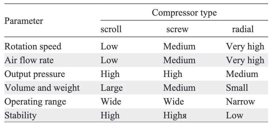
The power consumption of the air supply system can be more than 20% of the electrical power of the FCS. The following cooling methods can be used for closed cathode systems: passive, liquid and evaporative cooling.
5.2.1. Passive cooling
The passive cooling method offers a number of advantages, including a simple design, no power loss to the cooling system and no need for coolant circulation in the system. This increases the overall efficiency of the FCS[273]. PEMFCs utilise high thermal conductivity materials or heat pipes/vapour chambers as heat distributors. One disadvantage of the latter heat dissipation option is that it results in an increase in the mass and dimensional characteristics of the PEMFC.
The first method of passive cooling is to use high thermal conductivity materials as heat distributors. These materials absorb heat from the central region of the FCS and transfer it to the boundary regions of the device, where it is further dissipated into the surrounding air by means of natural convection[411, 412]. Copper, aluminium and carbon materials are used as heat spreaders[32, 273]. This cooling option is used in low-power devices.
For medium-power devices, the second passive cooling option is more suitable for use with heat pipes, which are highly efficient evaporative-condensation devices with high thermal conductivity in the range of 2100 – 50 000 W m–1 K–1[273]. This device can be thought of as a tube (made of copper, for example) from which air has been evacuated, containing a working fluid (e.g. alcohol, various nanofluids (see chapter 5.2.3, etc.) and a capillary layer (various porous materials) applied to the inner walls of the tube to return the condensed working fluid to the heating zone. As shown in Figure 26[98, 397, 413, 414], a capillary layer (various porous materials) is applied to the inner walls of the tube to return the condensed working fluid to the heating zone. During operation, when one end of the tube is heated, heat is transferred to the working fluid, converting it to vapour which condenses at the other end of the tube, releasing heat to the external environment. The capillary layer allows the cooling system to be used in both horizontal and vertical positions. The efficiency of a heat pipe is influenced by a number of factors, including the type of heat pipe, the nature of the used fluid, the shape and type of capillary material and the percentage of capillary material filling the tube volume[413, 414].
![[{"type":"paragraph","data":{"text":"Schematic representation of heat pipe operating principle."}}]](/storage/images/resized/nWB8XSXGTiBXGMV1sWYjU9pUTvL9y1s1vrsmbu7E_xl.webp)
In recent years, heat pipes have been successfully used as cooling elements for a number of electronic devices, including PEMFCs of different power[54, 397, 415-418].
5.2.2. Evaporative cooling
Evaporative cooling (or two-phase cooling) is based on the principle of phase transition (vaporisation) of the coolant, which is an evolution of the heat pipe approach[419, 420]. In this method, the coolant is vaporised in the working zone of the PEMFC, providing excess heat removal. Evaporative cooling is more efficient than air cooling and is comparable to liquid cooling, which will be discussed later. This cooling method is particularly suited to PEMFCs with high cooling requirements, offering a number of advantages over liquid cooling methods. These include increased heat removal rates, reduced coolant requirements, reduced energy consumption of the cooling system, reduced coolant pumping requirements and more uniform temperature distribution[413, 421]. Two-phase cooling can be divided into two categories: closed cooling (a development of passive cooling of the PEMFC using heat pipes) and open cooling (using water as a coolant).
The closed type of two-phase cooling implies working fluids with relatively low boiling points, including organic fluids such as HFE-7100 (methylnonafluorobutyl ether (C4F9OCH3), boiling point 61 °C)[21, 422] for LT-PEMFCs and water for HT-PEMFCs[98]. The coolants are supplied into separate cooling channels/plates. This method ensures a high level of uniformity in temperature distribution within the PEMFC. The main disadvantages of this method are: low reliability at critical heat flow and the mandatory presence of a condenser, which increases the size of the device.
In open type evaporative cooling, the temperature reduction of the PEMFC is achieved by injecting water, including directly into the reagent streams, rather than by circulating liquid in special channels[419]. In this instance, the injected liquid water evaporates, removing heat and humidificating the MEA of the PEMFC. The waste water vapour is then sent to a condenser for purification, where it is cooled and converted back to liquid water for reuse. The key benefits of this cooling method are that the injected water performs the dual function of cooling and humidification without the need for external humidifiers or separate cooling plates. Evaporative cooling can reduce the size of the heat sink by approximately 27% compared to the devices using liquid cooling[411, 419].
5.2.3. Liquid cooling
The use of water and other liquids as a coolant instead of air increases the cooling efficiency and reduces the size of the heat exchanger due to the many times higher value of heat capacity compared to air. Liquid cooling is preferable for FCSs larger than 5 kW, such as those used in electric vehicles[423, 424]. The working fluid in this type of cooling is mainly deionised water-based solutions circulating in cooling channels inside the BPs or in special cooling plates. In a typical closed-loop cooling cycle, the fluid passes through the PEMFC, absorbing its heat, which is dissipated to the environment in the heat sink, and then pumped back into the PEMFC to repeat the cooling cycle.
As with air cooling, the configuration of the flow fields (cooling channels) plays a significant role in the efficiency of heat dissipation in liquid-cooled systems. Examples of these flow fields can be seen in Figure 27. The search for the optimal geometry of the fluid flow fields is a pressing issue today[98, 423, 425]. From the perspective of temperature distribution uniformity, the optimal cooling solution is a modified (multi-pass) serpentine-type flow field (Figure 27c)[423]. The simplest parallel flow field (Figure 27a) demonstrated a lower pressure drop, but also exhibited the greatest non-uniformity of temperature distribution.
![[{"type":"paragraph","data":{"text":"Examples of coolant flow fields (channels) in BPs: flow field with parallel channels (a); single-pass (b) and doublepass (c) serpentine."}}]](/storage/images/resized/e4IB1NKjtxoHRwR6K9GHJLYUAUXZorgGf1sAkgey_xl.webp)
Nanofluids with excellent heat capacity and heat transfer are an alternative to water. They are prepared by dispersing nanoscale metallic and non-metallic particles in a liquid coolant (most often water, ethylene glycol, propylene glycol or various oils)[423, 426]. Nanofluids offer a number of advantages:
— the suspended nanoparticles, which have very large values of specific surface area, significantly improve the thermal performance of nanofluids, including thermal conductivity (heat transfer, thermal diffusivity) and regulate viscosity, which can both increase and decrease with the addition of nanoparticles;
— the nanoparticles can immobilise negative and positive ions from the coolant, reducing the need for a deionising filter in the cooling cycle;
— some types of nanofluids have very low freezing points (below –40 °C), and this can be seen as an advantage for PEMFCs operating at sub-zero temperatures (i.e. in cold-start mode);
— the nanofluids, due to their higher heat transfer, allow to reduce the size of the heat exchanger and the energy consumption of the cooling system.
The effectiveness of nanofluids can be demonstrated by the following examples. 1) The frontal area of the heat exchanger for a 2.4 kW PEMFC can be reduced by 21% by using a 0.05 vol.% concentration of TiO2 nanoparticles in a water/ ethylene glycol mixture (50/50 by weight)[426]. 2) The cooling rate is increased by 187% by using a 0.5 vol.% concentration of Al2O3 compared to a heat transfer fluid without nanoparticles based on a water/ethylene glycol mixture (60/40 by weight)[427].
It is important to note that nanofluids have a higher electrical conductivity than liquid coolants, which may result in electrical leakage and a subsequent decline in the electrical performance of the PEMFC. Furthermore, in certain instances, the incorporation of nanoparticles into a liquid coolant may result in an increase in viscosity, which may affect hydrodynamic losses[393]. It is therefore of the utmost importance to select the correct nanofluid composition in order for the PEMFC to meet the required design constraints and high hydrodynamic, thermal and electrical characteristics.
In this way, clear recommendations can be made and the scope of application of one system or another can be defined for the selection of cooling systems and methods of air supply to the PEMFC cathode. As a result, these tasks are currently limited to engineering modifications of pre-existing solutions for a specific PEMFC sample, despite their significant impact on the final product characteristics.
6. Conclusion
The efficiency of PEMFC operation is determined by four main parameters: (1) the conductivity of components, primarily the PEM and the catalytic layers, (2) the rate of electrochemical reactions at the electrodes, (3) the efficiency of reagent supply and reaction product removal, and (4) the efficiency of separating the anode and cathode gas spaces. At the same time, each of the parameters is determined by the properties of several components of the PEMFC, and the properties of one material can affect several characteristics simultaneously. The relationship between the characteristics and properties of the components of the considered PEMFC is complex and multi-parametric. It is important to note that an improvement in one material property can lead to an antibate effect on other parameters. For instance, a reduction in the membrane thickness results in a decline in ohmic losses in the PEMFC, but concurrently, an increase in crossover. Consequently, the optimum PEM thickness is that at which, with all other characteristics remaining constant, the maximum PEMFC power is achieved.
In order to systematise the data in the review the following should be noted:
One of the most important materials in a PEMFC is the polymer from which the PEM and the ionomer in the catalytic layer are made. The properties of this polymer have a significant impact on the gas permeability and proton conductivity of the PEM, the proton conductivity of the catalytic layers, and the lifetime of the PEMFC. Consequently, the polymer properties influence three of the four parameters that determine the efficiency of PEMFC operation: (1), (2) and (4). The target polymer conductivity characteristic is 0.1 S cm–1 over the full range of operating conditions and without degradation under the influence of hydrogen peroxide.
The next key component is the catalyst. Its electrocatalytic activity determines the maximum possible electric currents achievable during the PEMFC operation. However, these currents are determined not only by the activity of the catalyst, but also by the spectrum of other properties of the catalytic layer: the proton and electronic components of conductivity, gas permeability, and the ratio of hydrophilicity-hydrophobicity parameters. In terms of catalytic activity, platinum-containing catalysts with a particle size of 2 – 2.5 nm are optimal. The overall efficiency of PEMFC operation is primarily determined by the cathode catalytic layer, since the rate of oxygen electroreduction is several orders of magnitude lower than the rate of hydrogen electrooxidation. For the cathode catalytic layer, the optimum thickness is 10 – 15 μm. The properties of the catalytic layers primarily determine parameter (2) — the rate of electrochemical reactions at the electrodes. They also indirectly affect parameters (1) and (3), namely the balance of water transport in the electrodes. This affects both the overall conductivity of the MEA and the efficiency of reagent supply and reaction product removal.
From the point of view of the catalytic layer efficiency, one of the most crucial factors is the efficiency of reagent supply and reaction product removal. These characteristics are determined not only by the properties of the catalytic layers, but also by the complex properties of a number of other PEMFC components. The GDLs, BPs and the gas supply system are also important factors to consider. It is important to note that a significant step in increasing the specific capacity of the PEMFC has been achieved precisely by optimising the GDLs and BPs. Over the last 15 years, the thickness of the BPs has been reduced by almost 10 times (from 5 – 8 to 0.7 – 1.5 mm), resulting in a 3 – 5 times reduction in the volume and mass of the PEMFC, while maintaining the specific power.
The optimisation of the properties of the main components has led to a significant increase in the specific parameters of FCS. A number of FCS manufacturers claim to achieve specific power of MEAs in excess of 1.5 W cm–2, specific power of FCSs (excluding service equipment and coolant) in excess of 4 kW kg–1 and lifetime of up to 30 000 hours[428]. These characteristics enable power plants based on PEMFCs to compete with internal combustion engines in certain vehicle types. However, for a number of applications, the achieved characteristics of FCS are not yet sufficient. In particular, the specific power is insufficient for aviation applications, and the lifetime is insufficient for railway transport. The required values for the specific power of FCS are above 5 kW kg–1, and the lifetime is at least 50 000 hours. Furthermore, the cost of the power plants based on FCSs is still high, which poses a challenge to their mass introduction. A wide range of research is needed to achieve the required performance of the power plants based on PEMFCs.
It is clear that in order to achieve the best FCS performance, it is necessary to search for stable components of with specific composition and properties, including technologies for their integration into the PEMFC. In addition, it is essential to optimise a large number of operating parameters of the final device for each specific type of design and its specific operation conditions.
The main trends of the modern research in the field of the PEMFC can be divided into two main directions:
1) Optimisation of existing PEMFC developments (short-term perspective): increase in activity and stability of the platinum-containing catalysts; comprehensive improvement of the PEM characteristics by doping and reinforcement of existing perfluorinated sulphocationic polymer systems to increase specific capacity and lifetime; optimisation of materials and geometry of the BPs to improve mass-size indicators; improvement of manufacturability and mass production of FCS to reduce production costs.
2) Search for fundamentally new PEMFC materials and technologies (long-term perspective): development of new types of low-temperature ion-conducting materials with a focus on anion-conducting membranes, which will allow the use of platinum-free catalysts on both the cathode and anode of PEMFCs; development of fully solid-state, including polymeric, medium-temperature proton-conducting membranes; search for new free of charge catalytic systems (including biocatalytic systems) capable of providing efficient oxidation of organic fuels at low temperature.
7. List of abbreviations and symbols
BP — bipolar plate,
DL — doping level,
DOE — United States Department of Energy,
ECSA — electrochemically active surface area,
FC — fuel cell,
FCS — fuel cell stack,
GDL — gas diffusion layer,
HOR — hydrogen electrooxidation reaction,
HT-PEMFC — high temperature proton exchange membrane fuel cell,
ICE — internal combustion engine,
LT-PEMFC — low temperature proton exchange membrane fuel cell,
MEA — membrane electrode assembly,
MPL — microporous layer,
NHE — normal hydrogen electrode,
ORR — oxygen electroreduction reaction,
PEM — proton exchange membrane,
PEMFC — proton exchange membrane fuel cell,
PBI — polybenzimidazole,
PTFE — polytetrafluoroethylene,
RH — relative humidity,
TUI — temperature uniform index,
A — surface area,
\( \Delta H \) — enthalpy of reaction,
\( \Delta S \) — entropy change,
\( \Delta G^0 \) — Gibbs free energy change under standard conditions,
\( E^0 \) — standard electrode reaction potential,
\( E_{\text {ORR }}^0 \) — standard potential for oxygen electroreduction reaction,
\( E_{\text {HOR }}^0 \) — standard potential for hydrogen electrooxidation reaction,
\( \Delta E_L \) — voltage loss due to leaks through the electrolyte,
\( F \) — Faraday’s constant,
\( \Delta H^0 \) — change in enthalpy of the ongoing reaction under standard conditions,
\( i \) — electric current density,
\( i_0 \) — exchange current density of the reactions of electroreduction of oxygen and electrooxidation of hydrogen,
\( k \) — reaction rate constant,
\( \lambda_{\text {opt }} \) — optimal stoichiometry of input into fuel cell gases,
\( \lambda_{\mathrm{H}_2} \) — stoichiometry of input into fuel cell hydrogen,
\( \lambda_{\mathrm{O}_2} \) — stoichiometry of input into fuel cell air (calculated using oxygen),
\( \eta_{\text {act}} \) — activation polarization,
\( \eta_{\text {Ohm}} \) — ohmic polarization,
\( \eta_{\text {conc}} \) — concentration polarization,
\( P \) — specific electrical power,
\( p\left(\mathrm{H}_2\right) \) — partial pressure of hydrogen,
\( p\left(\mathrm{O}_2\right) \) — partial pressure of oxygen,
\( p\left(\mathrm{H}_2 \mathrm{O}\right) \) — partial pressure of water vapor,
\( \Delta Q \) — heat change,
\( \sigma \) — specific ionic conductivity,
\( T \) — absolute temperature,
\( \bar{T} \) — average temperature,
\( V \) — electrical voltage,
\( V_0 \) — equilibrium electrical voltage,
\( V_N \) — electrical voltage under non-standard environmental conditions,
\( V_t \) — thermoneutral electrical voltage,
\( V_{OC} \)— open circuit voltage,
\( \Delta W \) — net electrical energy,
\( z \) — number of electrons involved in reaction.
Acknowledgements
The work was performed in accordance with the state task of Federal Research Center of Problems of Chemical Physics and Medicinal Chemistry Russian Academy of Sciences (state registration numbers 122112100037-4 and 124013000692-4).
References


Fuel Cell Technical Team Roadmap, P. 34.


US Patent 3041317A
US Patent 3282875