![Schematic diagram of the SFMC/SPEEK/GO membrane.[35]](/storage/images/resized/jZ986c4BpFbzkCO6b8gn930cXZ4YiitDlC9KA0Mc_xl.webp)
![Schematic diagram of the SPAES/GO membrane.[36]](/storage/images/resized/BDcSt5VKd6SHRgnc7AhA7teyW1ZbdrnplSFBvL3D_xl.webp)
![Effect of AST on the Pt/C (a) and Pt/ATO (b) catalyst.[121]](/storage/images/resized/rYNEZbaAkJF7k7rxeQ0xN6TCKt1wkLET19Wel5qe_xl.webp)
![Photograph and schematic picture of the Au@Pt3Pd aerogel.[181]](/storage/images/resized/1t7GkSWdRk6IUFyXRoMotS3aReNbnnKfYZCULiJp_xl.webp)
![Schematic view of the Pd/PdAu/Pt NW/C nanoparticles.[174]](/storage/images/resized/87CP9W3Lo8O57wdv4NKfsuk1pNg4n4c08yvXyQvB_xl.webp)
![Schematic picture of the O-SMSI operation principle.[189]](/storage/images/resized/p30zHbSZiIMbaTqvRKsOCw2RGPVkJTwM39fP93GB_xl.webp)
![Schematic picture of the A-SMSI operation principle.[189]](/storage/images/resized/c53vDL6MUFFE6aCs6jVl3xrOI8BFzfYVL4RzL407_xl.webp)
![TEM image of Rh(6%)/TiO2.[191]](/storage/images/resized/9W6jnkxugnGipl0E5nPh2cwirOQBtVvCYocFHVW9_xl.webp)
![Schematic picture of PtAu/TiO2 NWs.[165]](/storage/images/resized/DR71X4HK7ksxUnUgCRYFKtpKXQMZYalghl9pNZjE_xl.webp)
![Schematic picture of operationof L-SMSI.[189]](/storage/images/resized/CljwG0kKdXzWVQbjpgLEsXTf8ESyVbD3BaQPxdX2_xl.webp)
Keywords
Abstract
The review addresses the problem of durability of operation of low-temperature proton exchange membrane fuel cells. Fuel cells are of considerable interest for the transition to renewable energy sources; however, the durability of these devices is still not sufficiently long (10 to 40 thousand hours). The increase in the durability is a relevant task. The review presents a systematic account and evaluation of the methods used for stabilization of electrochemical energy conversion systems with a proton exchange membrane and defines promising approaches to increase their lifetime.
The bibliography includes 197 references.
1. Introduction
Electrochemical energy engineering is an energy-saving technology due to high efficiency of energy conversion and high energy density of the energy carriers, particularly, hydrogen. Low-noise and self-sustainable operation of devices also contributes to good prospects of this technology. The development of systems such as low-temperature fuel cells (FCs), supercapacitors, and water electrolyzers gave rise to high requirements to the efficiency of electrode processes and operation time of the devices without considerable decrease in the performance. Meanwhile, authors often report high performance characteristics achieved for membrane electrode assemblies (MEAs) without paying attention to the long-term stability of operation.
As of 2024, hydrogen energy engineering continues to rapidly develop and is being integrated into the energy strategies of many countries. Renewable energy companies consider hydrogen as a key component of their decarbonization strategies, especially in combination with offshore wind and solar installations, which would stabilize power systems with intermittent green energy production. It is expected that the introduction of hydrogen in combination with carbon capture technologies would promote sustainable development of energy engineering and reduce emissions in a number of sectors such as industry, transportation, and utilities.[1]
The global growth of the market of hydrogen FCs is estimated, on average, to be approximately 24%, and by 2030, the market size could reach 11.87 billion US dollars.[2] The drive to reduce emissions and switch to clean energy stimulates investments and implementation of FCs, particularly in North America, Europe, and Asia-Pacific region where the technologies are supported by the government and through private investments.
The hydrogen FCs technologies are developed most actively for the use in transport. For example, Great Wall Motor has launched trucks equipped with 100 kW FCs capable of operating even at low temperatures down to –30°C. This is an example of adapting hydrogen systems for harsh environments. The GWM company plans to manufacture 10 thousands of these transport vehicles by investing more than three billion yuans in this project.[3]
Engineering innovations also play a key role. For example, BASF and HyPoint developed a new membrane that increased the power of FCs by 50%, which makes them promising for aviation and other highly energy-consuming spheres. These innovations considerably increase the energy efficiency and decrease the weight of fuel systems, thus expanding their applicability in new areas.[4]
Thus, hydrogen FCs show high potential for supporting the global transition to renewable energy sources, especially in the sectors of transport and off-grid energy systems, which ensures increase in the demand for these technologies in the coming years.
The durability of electrochemical devices and dynamics of deterioration of performance characteristics during operation are known to be fairly important consumer characteristics. The modern low-temperature solid polymer FCs are based on MEAs, a very large part of which is represented by products containing the proton conducting Nafion polymer. The working temperature of these devices is up to 100 – 120°C.
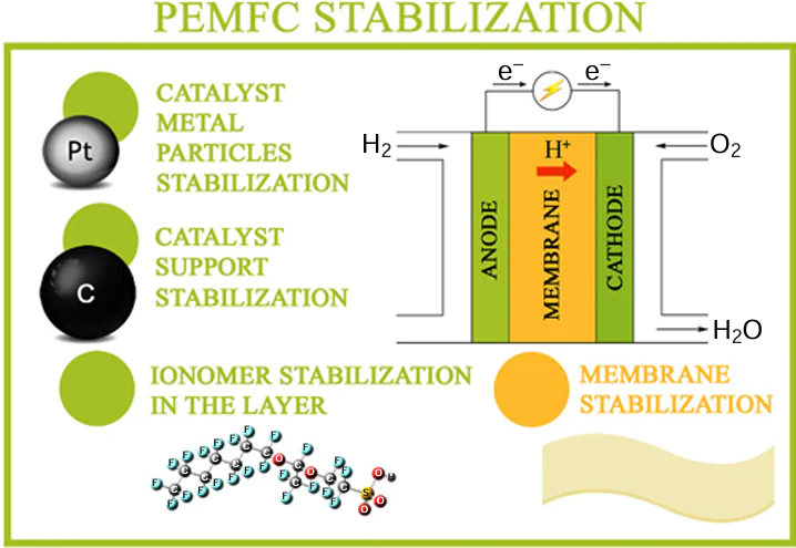
Fig. 1 shows the block diagram of the hydrogen – oxygen FC and the reactions that underlie the cell operation. As can be seen in the Figure, the cathode and anode compartments are separated by a proton exchange membrane, through which hydrated protons are transported. The fuel (hydrogen) and oxidant (oxygen) are supplied to appropriate electrodes where the half-reactions take place. Electrons move to the external circuit with a load.
![[{"id":"SQ9JVVBGr4","type":"paragraph","data":{"text":"Basic diagram of the low-temperature solid polymer FC."}}]](/storage/images/resized/mbNXYbz0XmOBqyN5UYSWcXnoactbpTH4MaqZRHkm_xl.webp)
The durability of modern MEAs is still too short: 10 000 h for trucks and 40 000 h for stationary applications. An increase in the durability (the target value is 40 000 h for trucks and 130 000 h for stationary applications)[5] would reduce the prime cost of the devices and make them more competitive. The MEA experiences several types of adverse impacts during operation including chemical, electrochemical, thermal, and mechanical impacts. The chemical impact includes oxidation of the metal and carbon components of the system in an oxygen environment and under the action of hydrogen peroxide. The degradation related to electrochemical processes includes electrooxidation of electrode components, dissolution of metals, and crystallization to give larger particles, component migration, metal dendrite growth into the proton-conducting membrane, and disruption of membrane integrity as a result of chemical and electrochemical redox processes induced by an electric field.[6-12] The thermal degradation is manifested as a local overheating of the ionomer, resulting in the ionomer dehydration or irreversible loss of sulfonic groups. The mechanical degradation is dangerous for the membrane and is manifested as membrane rupture caused by too large and/or frequent changes in the humidity, pressure, or temperature. These impacts modify the local structure and composition of electrodes and membranes, which most often deteriorates the performance characteristics such as open-circuit voltage, current density, power, and efficiency or cause the operation failure.
In order to prevent the adverse impacts on MEA and its components, it is necessary to enhance their resistance to the above types of treatment. Recent studies have considered various methods for stabilization of the components and materials that make up an electrochemical device. Nevertheless, due to the complexity and diversity of degradation processes, the issue of MEA degradation is still poorly understood. The same is true for the ways to control the adverse processes in MEA. This accounts for the difficulty of predicting and evaluating the durability of devices.
There are numerous accelerated and real-time tests that are carried out by different procedures, which hampers the comparison of MEAs developed by different research groups. Their applicability to particular situations is being debated. The review includes tables for each method for MEA stabilization. Although these tables are somewhat conventional, they will help specialists to perform the required comparative analysis and choose promising investigation avenues.
Despite some advances, prolongation of the durability of MEA operation remains a relevant issue.
The goal of the present review is to summarize, analyze, and integrate approaches and methods for stabilization of components of low-temperature proton exchange membrane fuel cells (PEMFCs), elucidate the physicochemical mechanisms of stabilization, identify the trends in the prolongation of the durability of electrochemical systems and promising lines for further research and, what is important, for practical applications.
Although reviews devoted to the durability of electrochemical systems have already been published, it should be noted that they mainly address the degradation aspects of this problem. For example Xie et al.[13] considered the degradation mechanisms of MEA components. The review by Wallnöfer – Ogris et al.[14] focuses on FCs, including the mechanisms of their chemical, electrochemical, and mechanical degradation and poisoning effects that influence the durability, performance, and functions of components of PEMFCs and considers the relationship between the operation conditions and degradation mechanisms. However, the review gives no data on the stabilization mechanisms. The authors also studied approaches for counteracting the degradation in terms of aging mechanisms. Zhang et al.[15] addressed the degradation mechanisms of FCs used in transport vehicles, with the attention being focused on the start/stop conditions. The authors list solutions in terms of material improvement and system control.
In our review, the attention is concentrated on the methods, approaches, and mechanisms of stabilization of components that are most susceptible to degradation due to the specific features of electrochemical system. The focus of our review is the MEA and its components (support, catalyst, ionomer, and membrane). These components are subjected to the main corrosion attack, and their stabilization would provide the most significant effect.
2. Key parts of the membrane electrode assembly: functions and requirements to characteristics
The membrane electron assembly is the main energy conversion unit in a low-temperature FC.[16-19] Meanwhile, it is subjected to the greatest destructive action, since the electrochemical processes inducing the component degradation take place particularly in MEA.
A large group of devices is represented by PEMFCs. Among them, proton exchange membrane devices are used most extensively due to a number of reasons. The membranes are made of polymers prone to dissociation to give a mobile hydrated proton and a polymer acid residue. The FCs that operate at relatively low temperature (up to ~ 80 – 100°C) are commonly called low-temperature FCs.
The membrane separates the cathode and anode compartments and isolates the oxidant and the fuel from each other, thus preventing the electrical contact of the cathode and the anode, while providing the ionic current (the current of hydrated protons) from the anode to the cathode. According to its functions, the membrane should have the following properties, which should be preserved throughout the operation of the device:[20]
(1) low gas permeability and permeability to other reagents (< 1 × 10⁻⁶ cm3 cm–2 s–1 atm–1 or < 1 mA cm–2 for hydrogen). Membranes should have low hydrogen and oxygen permeability to prevent them from mixing, which could lead to the loss of efficiency;
(2) high electronic resistance;
(3) high ionic conductivity [0.1 – 0.2 S cm–1 at 80 – 100°C and 100% relative humidity (RH)], which is needed for effective FC operation. For modern membranes, the conductivity must remain high at various temperatures and humidity levels;
(4) high mechanical strength (tearing strength of ~ 30 – 50 MPa, elastic modulus of 200 – 500 MPa in the dry state and 10 – 50 MPa in the wet state, strain at break of 100 – 250% in the dry state and 200 – 400% in the wet state). The membranes must withstand mechanical stresses during FC manufacture and assembly and long-term operation. The tensile strength of the membranes should ensure the membrane integrity during operation at high temperatures and high pressures of the gases supplied to the membranes. Membranes with poor mechanical properties expand too much upon saturation with water, while fast and frequent temperature and humidity changes cause repeated expansion and contraction of the membrane, resulting in the mechanical degradation;
(5) thermal stability at high temperatures (up to 120°C);
(6) high water-retention capacity (water uptake of ≥ 20 mass% at 100% RH). The ability to retain water at low and high humidity is important for stable conductivity;
(7) low degree of swelling. The required level of ionic conductivity is retained in the membrane only when it is wet, and increase in the membrane volume upon water absorption should be minimized;
(8) chemical stability. The membrane must be stable to the chemical action of the environment in which it operates. It is known that electrochemical processes involving water (correspondingly, hydrogen and oxygen) proceed via a number of sequential and parallel competing reactions. The formation of hydrogen peroxide (two-electron mechanism) is an undesirable reaction in the context of efficient energy conversion. Hydrogen peroxide formation and degradation involve generation of some amounts of •OH and •OOH free radicals. Due to their high reactivity, free radicals degrade the MEA components during the operation.
The electrodes (cathode and anode, see Fig. 1) are parts of MEA in which the electrochemical reactions take place. The main function of electrodes is to ensure high reaction rates, effective transport of charges (electrons and hydrated protons) and matter (the oxidant and the fuel, water, and electrochemical reaction products). According to their function, the electrodes have mixed (proton and electronic) conductivity and porous structure.
The electrodes should ensure stability of electrocatalytic characteristics and transport properties throughout the lifetime of the device, which is at least 10 000 h for transport applications and at least 40 000 h for stationary installations.[5] The maintenance of stability requires an invariable structure of electrodes at operating temperature in the 60 – 80°C range and 50 – 80% RH.
High reaction rates are provided by using catalysts, most often, platinum or platinum alloy nanoparticles, with characteristics corresponding to high requirements to the mass activity (MA) [at least 0.4 – 0.5 A mg(Pt)−1] and specific surface activity (SA) [at least 0.7 – 1 mA cm(Pt)–2]. The catalysts are supported on a material (most often, carbon black) with a high conductivity (approximately 100 – 200 S cm−1) to provide for effective electron transport. It is important to maintain a large electrochemically active surface area (ECSA) of the catalyst, which is approximately 50 – 70 m2 g(Pt)−1; this substantially increases the platinum utilization efficiency.
The proton conductivity in the electrode is provided by an ionomer (a proton exchange polymer similar to the membrane material) to minimize the loss during hydrogen ion transport.
In addition, the electrodes should have an optimal porosity and thickness: a 10 – 50 μm-thick microporous gas diffusion layer (GDL) with a porosity of 40 – 70% and a 5 – 10 μm-thick catalyst layer, which promotes uniform distribution of reactants and removal of reaction products.
All of the listed characteristics are responsible for the efficiency and durability of FC.
Interfacial contacts. Since we are considering electrochemical devices, an important feature influencing the durability is the stability of interfacial electrical contacts of particular elements: collector plates/GDL/electrode/membrane. The transport of charges (electrons and hydrated protons) occurs through these interfaces.[21]
The modern electrochemical systems and energy conversion devices are still in the stage of rapid development; therefore, a serious problem is the lack of a unified system of requirements and performance evaluation methods, that is, there is no standardization. Various researchers use and report different approaches and methods to evaluate the durability. Since the tests take a lot of time (thousands or even tens of thousands of hours), so-called accelerated stress test (AST) and accelerated durability test (ADT) are often used.
Currently, the standard durability tests of electrochemical devices are based on the US Department of Energy (DOE) protocols.[22] The requirements to particular components of the device and the whole device are also developed by DOE.
3. Ionomer stabilization
The ionomer, unlike the membrane, is distributed throughout the electrode. The ionomer macrostructure is either a polymer film or clusters located on the surface of other electrode components (carbon black, platinum, etc.). A separate subject of research or related technology is the stability of Nafion ionomer (including its analogue MF-4SK [23]) and related Aquivion ionomer[24] within MEA.[25-29] As stated above, the primary function of the ionomer is to transport the hydrated protons. Depending on the engineering implementation (membrane or ionomer distributed in the electrode), additional requirements appear. A membrane should isolate the electrode compartments, but should be permeable to water. As opposed to membrane, ionomer distributed in the electrode should be permeable to reactants to ensure the access of reactants to the electrocatalyst. This is attained by fabrication of various ionomer structures (films, islands, etc.). It is important that the initial properties and structure of the ionomer are retained during functioning. Since ionomers are high-molecular-weight polymers, they tend to change the supramolecular structure and undergo various types of degradation: oxidative degradation, thermal degradation accompanied by water loss, thermal degradation accompanied by the loss of functional groups, and polymer backbone degradation. In addition, ionomers are prone to colloidization (dissolution to form colloidal particles) on contact with water and other solvents and to electrophoretic migration in an electric field. Ionomers implemented as membranes are susceptible to mechanic degradation due to the mechanical stress caused by pressure, temperature, and humidity changes.
The methods for increasing the ionomer durability are expected to suppress these adverse processes and stabilize the ionomer in the initial state with retention of its functional characteristics.
The greater part of publications is devoted to stabilization of membranes in the MEA. Much less studies address the degradation and stabilization of ionomers distributed throughout the electrode layer.
Fig. 2 depicts the main causes for degradation of ionomers and possible stabilization methods. It should be borne in mind that the listed stabilization methods can be directed against several degradation mechanisms at once.
![[{"id":"JYUAvfC5Pe","type":"paragraph","data":{"text":"Causes for degradation and methods for stabilization of ionomers in an electrode layer."}}]](/storage/images/resized/2fyqbZxuHJAJQFFGqW4OSevc0em8pNagqBhjp0oe_xl.webp)
3.1. Membrane stabilization
The methods used for membrane stabilization can be subdivided into two major approaches: reinforcement and filling, which are depicted in Fig. 3.
![[{"id":"p53Cv8rnY4","type":"paragraph","data":{"text":"Schematic picture of membrane stabilization: (<i>a</i>) reinforcement, (<i>b</i>) filling. PTFE is polytetrafluoroethylene."}}]](/storage/images/resized/rw5HMgQEPC52uQT5dG9Uh9cG9n6jxXnJT3ooB3av_xl.webp)
3.1.1. Reinforcement
The aim of reinforcement is to improve the mechanical properties of membranes. The application of reinforcing coatings increases the tensile strength of the membrane and decreases the fluidity and colloidization (dissolution) during the membrane operation. Furthermore, reinforcement can increase the membrane durability by generating a barrier layer and prevent the dendritic growth of metals into the membrane.
The perfluorosulfonic acid (PFSA) ionomer membranes (most often, Nafion®, Fig. 4) are currently the prototypical proton exchange membranes in PEMFCs, for which durability is still a technical barrier preventing commercialization.[26]
![[{"id":"4i7Ph4F424","type":"paragraph","data":{"text":"Structural formula of Nafion®."}}]](/storage/images/resized/grtz1S0wVVySJ9AeQaRrhQ0vAZvNtxBWfbtcO369_xl.webp)
Regarding the durability requirements, reinforced and/or stabilized PFSA membranes have started to attract a lot of interest, because they showed a greater durability in PEMFCs than their non-reinforced analogues.
The reinforcement consists in the generation of various polymer networks [26][27] or matrices,[28] which increase the Nafion durability and provide a high mechanical strength of the membranes.
The membranes reinforced with a porous PTFE support layer were manufactured from short-side-chain PFSA using the annealing method (Fig. 5). The reinforcement followed by annealing reduced not only the water uptake and swelling ratio of 3M and Aquivion membranes, but also the proton conductivity by changing the size of ion channels.[27]
![[{"id":"V5Sznm2cyz","type":"paragraph","data":{"text":"Reinforcement of membranes with PTFE followed by annealing.[[ type=\"anchor\" referenceId=\"13417\" ]] SSC-PFSA is short-side-chain perfluorosulfonic acid."}}]](/storage/images/resized/20nO1o2bvk4dT9J9JkGUIvTG297T4iS0XzIFwSmy_xl.webp)
The fabrication of the reinforced membrane is sketched in more detail in Fig. 6. A PFSA solution was applied onto a glass plate by means of a doctor blade, thus forming the bottom layer of the membrane. A porous PTFE substrate, which served as a reinforcing layer, was applied on top of the bottom PFSA layer. The second casting of the PFSA solution gave the top layer of the membrane.[27]
![[{"id":"UqcvUrDxTr","type":"paragraph","data":{"text":"Design of the PTFE-reinforced membrane."}}]](/storage/images/resized/zMrFlUoBuik6GzdNiA0ZFyjpz2HGaNgDSdgYCulB_xl.webp)
A known method for the fabrication of a reinforced membrane implies impregnation of a porous polytetrafluoroethylene film with a suspension of the Nafion ionomer. Jao et al.[25] noted that the PTFE/Nafion composite membrane is characterized by low cost, high mechanical strength, and low swelling. The authors compared the durability and service characteristics of PTFE/Nafion MEA with those of commercial Nafion 211 MEA. Despite the improved mechanical strength, the reinforced membrane tested in MEA showed a 66% decrease in the power density after 1040 ADT cycles. Meanwhile, the Nafion 211 membrane demonstrated a 50% decrease under the same conditions. The authors stated that the reinforcing PTFE film prevents the hydrogen crossover even when the main Nafion membrane is ruptured. This is manifested as a less pronounced decrease in the open circuit voltage (OCV) after the rupture in the case of the reinforced membrane, which was 227 μV per testing cycle vs. 697 μV for the pristine Nafion 212 membrane.
The reinforcement of membranes with sulfonated carbon nanotubes (CNTs) has been reported.[30] The authors fabricated multilayer composite membranes made of sulfonated CNTs/Nafion. The multilayer structure in composite membranes promotes the alignment of sulfonated CNTs and proton-conducting pathways in the lateral direction (parallel to the membrane interface). The multilayer structutes demonstrated high proton conductivity due to orientation of proton-conducting pathways along the CNTs, high water uptake due to the formation of a hydrophilic interface between the layers, and good mechanical properties. At 80°C, the proton conductivity of the multilayer CNTs/Nafion membranes decreased slightly, whereas in the case of multilayer pristine Nafion membrane, the proton conductivity dropped below 90% of the initial value. This attests to an increased electrochemical stability of membranes containing CNTs.
The Nafion/PTFE-based membrane impregnated with hydrophilic polydopamine (PD) and resveratrol 3,5-(OH)2C6H4 – CH=CH – C6H5-4-OH as a free-radical scavenger showed a low hydrogen crossover (less than 20 mA cm−2) after eight OCV cycles in the ASTs, whereas for the same membrane without resveratrol, crossover increased to 80 mA cm−2 over three OCV cycles of ADT.[31]
Ultrathin membranes are of interest because of their low ionic resistance. To prevent thin membranes from mechanical fracture, Yao et al.[32] reinforced 8 and 12 μm-thick PTFE membranes. After 71 thousand cycles of accelerated combined chemical and mechanical durability testing, the hydrogen crossover across the membranes increased from 3 to 15 mA cm–2, which is markedly higher than the DOE target value.
The reinforcement is meant not only to increase the mechanical strength of the membrane, but also to counteract other effects such as colloidization and chemical degradation, which may arise during long-term operation of FCs. This markedly improves the membrane stability and durability by reducing the impairment of performance characteristics at high temperatures and under the action of moisture. This is favourable for the general efficiency and durability of PEMFC. At the same time, this approach to stabilization decreases the effective surface area of the membrane and, therefore, deteriorates the proton transport properties.
3.1.2. Filling
The use of fillers to create composite (filled) membranes, the second stabilization method, has proven to increase the membrane stability to water loss and chemical and thermal stability.[30] [33-38] Filling implies modification of ion exchange materials and production of hybrid membranes containing inorganic nanoparticles. For this purpose, an additive such as ceria, titania, or silica is added to an ionomer solution. The mixture is stirred for homogenization, and the membrane is cast in the usual way. After drying to remove the solvent, the membrane containing the added particles is taken away from the substrate. It was noted that the increase in the conductivity and selectivity attained for the hybrid membranes is mainly due to the change in the pore and channel structure and distribution of the carrier ions in the membranes.[39] The chemical stability increases because of recombination of hydroxyl radicals, which are formed during MEA operation. The radicals result from the two-electron reduction of oxygen at the cathode or the chemical reaction between hydrogen and oxygen that have passed through the membrane both on the cathode and on the anode [Eqns (1) – (6)]. The radicals formed in this way react with the polymer side chains in the membranes or with the sulfonic acid groups to give the R – CF2•; this is followed by polymer oxidation and release of HF [Eqns (7) – (10)], resulting in chain cleavage, change in the structure, and loss of functional groups.[40] In the presence of an additive, free radicals react with the additive and thus lose the unpaired electrons. The stability of materials to free radicals is tested using the widely known Fenton’s test.
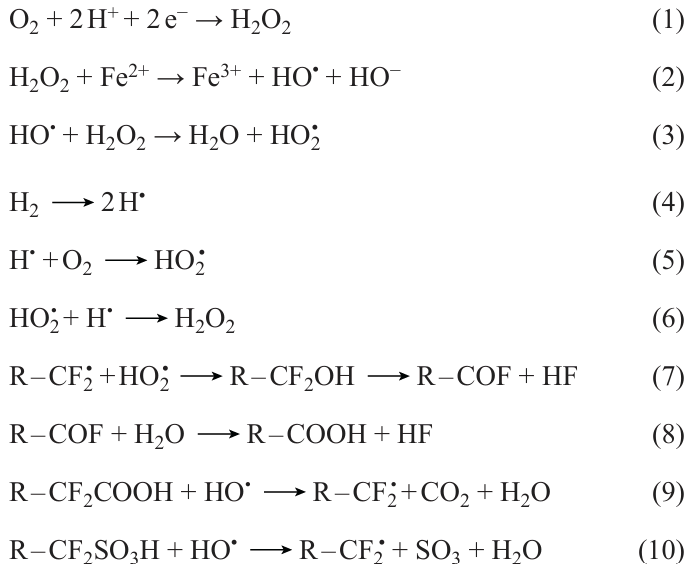
The stability of ionomers to chemically harsh environments can be increased in two ways, either by adding components that would absorb chemically reactive species or by using more inert materials. The application of these approaches and their combinations has been reported in the literature.
Teixeira et al.[40] proposed new modified Nafion membranes doped with bis-phosphonic acids highly resistant to chemical degradation induced by H2O2/Fe2+ (Fenton’s reagent), which mimics a radical attack ex situ on the membrane structure. The molecules of these acids are composed of a benzene ring with phosphonic groups (–H2PO3) as substituents. The bis-phosphonic acids were introduced into a standard Nafion membrane in view of their good proton conductivity and antioxidant properties. The authors assumed that these additives promote radical recombination. The corresponding properties were evaluated by the Fenton’s test,* attenuated total reflectance Fourier transform IR spectroscopy, and scanning electron microscopy (SEM) before and after the chemical decomposition. The new membranes showed very good chemical stability after oxidative degradation in the Fenton’s test at 80°C and longer durability than commercial Nafion 115 membranes. The proton conductivity of the membranes after chemical degradation was estimated by electrochemical impedance spectroscopy, which revealed a decrease in the proton conductivity for all membranes, but the conductivity values both before and after the Fenton’s test were higher for the new modified membranes than for Nafion 115.
Agarwal et al.[41] proposed an effective solution to the membrane degradation problem consisting in the introduction of radical scavengers such as polyvalent metal ions (e.g., cerium and iron ions), which mitigate the chemical action on the membrane by recombining free radicals. However, at the same time, the added ions migrate during the FC operation and cause a decrease in the durability and performance via interaction with various FC components (Fig. 7a). In order to suppress the migration, the authors used immobilization (restriction of the mobility) of the added ions (Fig. 7b). They fabricated the CRE-F (crown ether-functionalized) and CRE-I (crown ether-impregnated) membranes. The CRE-F membranes were fabricated by covalent functionalization of Nafion™ with 15-crown-5 ether molecules. For this purpose, the sulfonyl chloride form of the membrane in DMF solution was treated with A-15C5 (2-aminomethyl-15-crown-5 ether) and triethylamine. Then the membrane was dissolved in DMA, cerium nitrate was added, and a film was cast and annealed for structure stabilization. The CRE-I membranes were produced by impregnating Nafion with 15-crown-5 ether and cerium nitrate compounds. For this purpose, Nafion was also initially dissolved, all reactants were mixed, and the membrane was cast from the resulting dispersion. Owing to the stabilizing action of crown ether on cerium ions, the retention of cerium increased by more than 300% and the chemical stability increased by 80%. The migration under the potential gradient can be eliminated, and the complex is also beneficial for the radical scavenging activity. In the case of cerium-doped membrane without crown ether stabilization, a sharp increase in the hydrogen crossover and in the fluoride ion concentration takes place after 310 h of AST, whereas in the case of the cerium-doped and crown ether-stabilized CRE-I membrane, the increase in the crossover and concentration of fluoride ions occurs only after 552 h.
![[{"id":"9raw-Ptv63","type":"paragraph","data":{"text":"Schematic view of cerium ion migration (<i>a</i>) and cerium immobilization as crown-ether complexes (<i>b</i>).[[ type=\"anchor\" referenceId=\"13431\" ]]"}}]](/storage/images/resized/uT22NZWxLrUhE4H7Ulk4Bt498D0WIimBteOkTsRI_xl.webp)
Tsipoaka et al.[42] reported a scalable and simple method for the formation of cerium titanium oxide (CTO) nanoparticles dispersed on smooth carbon nanofibres (CNFs) (CTO/CTO@CNFs). It was shown that incorporation of CTO/CTO@CNFs as an additive mitigating the degradation into the Nafion ionomer provided a membrane with a durability of more than 400 h. During the 400 h durability test, the modified membrane surpassed the state-of-the-art Nafion 211 membrane in the fluoride release rate. The decrease in the power output was 40%.
Wang et al.[43] added cerium oxide CeO2 to GDL rather than to the membrane to increase the stability of Nafion membranes. When cerium ions are added to the membrane, they have a large contact surface with ionomer molecules and can replace the hydrogen ion in the membrane sulfonic groups and thus decrease the proton conductivity. When cerium oxide is immobilized on GDL, the contact area with the membrane decreases, while the role of CeO2 as the free radical scavenger is retained. After 400 h of testing (AST), the decrease in the power density for MEA with modified GDL was only 11.7%, whereas this value for MEA with standard GDL was 41.7% for the same initial power density of 1.2 W cm–2.
* The Fenton’s test is verification of the membrane stability to oxidants by treating it with a hydrogen peroxide solution with iron ions, which generate highly reactive hydroxyl radicals.
3.1.3. Application of more stable ionomers
The approach involving more inert and stable ionomers (compared to Nafion) is also widely addressed in the scientific literature.[44-46]
As alternatives to PFSA, aromatic compounds have been proposed. In the membranes based on aromatic compounds, the aromatic rings are connected in chains and contain ether, ketone, sulfone, imide and benzimidazole groups.[36] Aromatic compounds are of interest because of the conjugation energy, which makes the compounds resistant to external impacts (oxidation, heating) and to addition reactions. Aromatic compounds are prone to electrophilic substitution reactions and, hence, they often take the corrosion attack by inducing free radical recombination. Liu et al.[44] noted that the mechanical strength and ionic conductivity of proton-conducting membranes are counteracting properties that are difficult to achieve simultaneously. An increase in the proportion of sulfonic acid groups with a decrease in the equivalent mass of membranes leads to higher proton conductivity, but simultaneously deteriorates the mechanical strength and resistance to water, which affects the durability and performance of FCs.
Fig. 8 gives examples of compounds used as alternatives to conventional Nafion to increase the stability of MEA operation. These compounds are used to fabricate proton-conducting membranes, in some cases, in combination with reinforcement or filling. Their use provides better water uptake properties compared to those of Nafion [47] and a sufficient mechanical strength for the PEMFC applications.[37] [48]
![[{"id":"k6ugGd1jEF","type":"paragraph","data":{"text":"Structural formulas of compounds used as alternatives to Nafion."}}]](/storage/images/resized/O7XP8HRtN4QGvKUZbBCpkacW4dp0rwScXViSKWDI_xl.webp)
However, the studies in which the alternative membranes are investigated using AST or ADT methods are scarce. For example, Nemeth et al.[49] reported the results of AST for such aromatic membranes. In order to alleviate the radical attacks, the authors used the antioxidant strategy, that is, doped the membrane with Cu(II) porphyrin.[2] The antioxidant doping improved the PEMFC durability: according to the results of AST performed at high RH, the lifetime increased to 60 h (by 20%). Also, AST showed that in the case of non-modified membranes, the high-frequency resistance almost doubled (increased from the initial value of 44 to 81 mΩ cm2), while for the modified PEMFC this increase was only 10% (from 43 to 48 mΩ cm2). In addition, the ion exchange capacity decreased by almost 60%. Before AST is carried out, one can only indirectly consider the stability of these membranes during MEA operation.
Kononova et al.[45] demonstrated good prospects of polysulfonic acid imide [BDSA-SPI-4 (H)] as a proton-conducting membrane polymer for electrochemical devices that perform direct energy conversion in the FC mode; the maximum electrical power of ~ 170 mW cm–2 was detected in the oxygen – hydrogen system at room temperature and atmospheric pressure.
A method of membrane reinforcement with polyphenylsulfone (PPSU) has been reported.[50] The addition of PPSU to membranes based on aromatic polymers [polyether ether ketone (PEEK) and sulfonated PPSU (SPPSU)] reduced the undesirable mass uptake, which causes mechanical degradation of membranes, from 181 to 105% without a substantial decrease in the conductivity (29 and 21 mS cm–1 for the non-reinforced and reinforced membranes, respectively).
It was noted[46] that membranes based on aromatic compounds have a higher potential as conductors owing to their electrochemical, mechanical, and thermal stability. However, ion-exchange membranes based on polyaryl ether ketones and polyimides do not have sufficient proton conductivity and strength to be used in FCs. Therefore, it is necessary to develop appropriate modifications to counterbalance these drawbacks.
A cross-linked sulfonated polyphenylsulfone (CSPPSU) membrane[51] was tested for the durability in MEA, which showed a lower initial power and a more pronounced decrease in the power after 4000 h of testing compared to MEA with the Nafion 212 membrane. The authors noted a reduced proton conductivity due to cross-linking, but higher mechanical and thermal stability of the membranes. The degree of cross-linking should be optimized to improve the membrane performance.
3.1.4. The use of carbon materials
The thermal stability and operation durability of PEMFCs are important characteristics, which are addressed in quite a few studies.[52-61]
A separate and relatively new trend is the use of carbon materials in Nafion-based proton-conducting composite membranes in order to improve their characteristics such as water uptake at elevated temperatures, ionic resistance (conductivity), and thermal stability.[33-35] The use of carbon materials belongs to membrane filling methods; however, because of the unique properties of carbon materials (regular structure, nanoscale particle size, the possibility of specified surface functionalization), we consider this approach in a separate Section. The methods for introduction of additives such as CNTs [30][35] and graphene materials [35-37] into the membrane bulk vary depending on the goal. This may be mere mixing of components, or deposition of the additive on the membrane surface by various techniques (spray printing, ultrasonic spray coating, electrophoresis, etc.). This approach makes it possible to modify the polymer structure, including micropores and channels, and to control the hydrophilic properties.
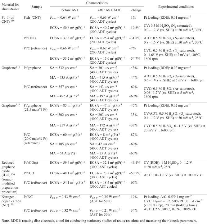
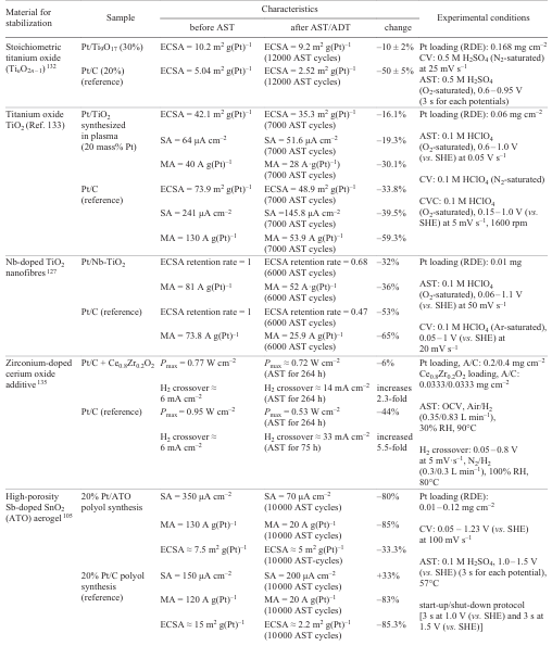
For example, Rambabu et al.[35] fabricated a membrane consisting of sulfonated fluorinated multiblock copolymer (SFMC), sulfonated polyether ether ketone (SPEEK), and 1 or 5 mass% graphene oxide (GO). GO acted as a hydrogen barrier and promoted the transport of protons (Fig. 9).[35] A composite membrane consisting of sulfonated polyarylene ether sulfone and graphene oxide (SPAES-GOx) was also manufactured (Fig. 10); GO served for preventing swelling of the membrane and increasing the proton conductivity.[36]
Fig. 11 outlines the main causes of the membrane degradation and possible stabilization methods. It should be borne in mind that the listed stabilization methods are aimed at eliminating several causes for degradation at once. Each of the presented methods usually combines chemical, mechanical, and thermal approaches to stabilization.
![[{"id":"A9GMYqBamU","type":"paragraph","data":{"text":"Causes for degradation and methods for stabilization of membranes."}}]](/storage/images/resized/WkILT8GsLV0YBRFtuQSex6Dn8C7sfmAoXrZT0kvx_xl.webp)
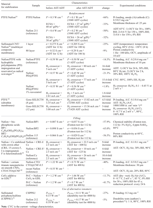
Table 1 presents a comparative analysis of various membrane stabilization methods. The table contains the results of investigations of series of samples using various AST or ADT methods. Each series of samples includes one or a few stabilized samples and one reference sample. The main parameters for evaluation of stabilization methods are power (P), ECSA measured by cyclic voltammetry (CV), specific proton conductivity (σ), and H2 crossover measured under identical conditions before and after the durability tests.
3.2. Ionomer stabilization in the catalytic layer
As noted above, the vast majority of publications consider membrane stabilization issues and pay little attention to the ionomer in the electrode layer. Meanwhile, this is an important aspect for the durability of an electrochemical device.
In order to increase the electrode durability, it is necessary to preserve not only the structure of the proton exchange material, but also the major function of the material, that is, the ability to transport protons. The ionomer in the electrode is affected by electric field, corrosive environment, and elevated temperature. A significant and relatively poorly known factor causing degradation of electrodes is redistribution of the Nafion polymer within the electrode because of colloidization and migration. As a result, the electrode structure is markedly disturbed: inhomogeneity appears, the resistance to proton transport increases, and gas diffusion resistance changes. Accordingly, ionomer stabilization should be structural, chemical (electrochemical), and thermal.
A relatively small number of studies devoted to ionomer stabilization use structuring-based approaches,[63-67] which give rise to stable structures during functioning of electrode layers and to interfacial interaction between the ionomer and other electrode layer components, and kinetic stabilization approaches based on the introduction of free radical scavengers into the electrode, as it is done for membranes.
A promising way to increasing the ionomer stability is to enhance the interfacial interaction between the components, e.g., by obtaining adsorption and chemical surface compounds that would increase the corrosion resistance and structural stability and by extending the operating temperature range.[56-61] The cited studies consider the interaction of proton exchange Nafion polymer with the surfaces of platinum and various carbon materials such as carbon black, multi-walled CNTs, and graphene. It was shown that carbon materials with high surface area (graphene) markedly increase the thermal stability of the polymer. The Nafion-C interfaces were studied by NMR and X-ray photoelectron spectroscopy (XPS); strong interaction accompanied by the formation of surface chemical compounds involving covalent bonds was found (Fig. 12).
![[{"id":"wXgs8oL_WX","type":"paragraph","data":{"text":"Ionomer stabilization by deposition on graphene."}}]](/storage/images/resized/AXvA90uLSlW7Y70qz9lCvhUYVuPlnJHsKG9T1Xqx_xl.webp)
An important mechanism of electrode degradation is electrophoretic migration of Nafion. Nechitailov et al.[68] demonstrated the pronounced effect of the electrode porosity on the degradation rate. High porosity results in increasing rate of migration of the components. In the case of highly porous electrodes, electrode inhomogeneity along the electric field gradient appears, and the resistance to the proton transport increases. Analysis of scientific literature indicates that electrophoretic migration of the ionomer during MEA functioning has not received adequate attention. The details of these processes are poorly investigated.
A known method[69] for increasing the stability of the proton-conducting component in the catalytic layer involves the use of sulfonated silica (SiO2). The sulfonated silica ionomer proved to be stable during AST. This ionomer retards the agglomeration of Pt particles.[69] A silicate structure grows around the catalyst particles, which strengthens the material by preventing particle dissolution and agglomeration. Table 2 presents comparative analysis of various designs of this stabilization method. The change in ECSA and the power before and after AST were the key evaluation parameters.
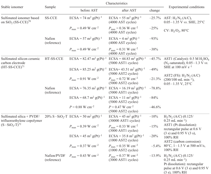
Analysis showed that alternative materials based on SiO2 [sulfonated ionomer based on SiO2 (SS-CCE),[70] sulfonated silica ceramic carbon electrode (HT-SS-CCE),[71] sulfonated silica with PVDF – trifluoroethylene copolymer (S – SiO2-T)[72]] provide a much higher stability of ECSA and power than Nafion. This makes these materials promising candidates for FC applications.
3.3. Summary
Thus, it follows from the published data that degradation of ion exchange materials occurs by several pathways, which are often interrelated. The most significant among them are mechanical destruction, chemical degradation due to a radical attack, thermal degradation associated with dehydration and with structural breakdown, colloidization, and ionomer migration in the electric field.
The described approaches to ionomer stabilization in MEA are reduced to mechanical stabilization (reinforcement), thermodynamic stabilization based on the formation of stable composites and surface compounds (e.g., Nafion-C interface), kinetic stabilization using scavengers that reduce the free radical concentration (filling with cerium compounds or using aromatic polymers), and structural stabilization (the use of nanostructured materials such as graphene and SiO2) (Fig. 13).
![[{"id":"74g7-qriZx","type":"paragraph","data":{"text":"Methods for ionomer stabilization in the catalytic layer."}}]](/storage/images/resized/Aywu3KdNc4hPe8MetAQGMdwXAH1DjrRORSqGtKcY_xl.webp)
4. Electrocatalyst
The catalyst is an important part of MEA in PEMFC.[73-77] It provides acceleration of very slow reactions, e.g., oxygen reduction in oxygen – hydrogen FC, oxidation of methanol, or other organic compounds, in methanol, or other liquid, FC, up to reasonable rates.
In the traditional implementation, the catalyst represents particles of platinum, platinum metals, or alloys supported on carbon (carbon black). A model of such catalyst is depicted in Fig. 14. The particles of ion exchange material, the features of which are discussed in the previous Section, are located on the surface of catalyst particles.
![[{"id":"u-eJD9hieu","type":"paragraph","data":{"text":"Model of the Pt/C catalyst."}}]](/storage/images/resized/hzSDIoF5CdYRVZCB3blefqvCHEgthlfaIyOc9OU4_xl.webp)
The catalyst is highly vulnerable to complex corrosion processes that affect both the carbon support [77-82] and the metal (platinum or platinum-based alloys).[83-85] The corrosion of electrocatalysts should be studied for understanding the mechanisms of catalyst degradation and for taking adequate measures to mitigate these processes.
4.1. Corrosion of the carbon support
The carbon support tends to undergo oxidative corrosion because of its thermodynamic properties (relatively low equilibrium oxidation potential) or high surface area. The potential difference of ~ 1.2 V, which is generated during PEMFC start-up and shut-down, promotes intense oxidation of carbon black.[77-81] The oxidation of carbon gives, apart from other compounds, carbon monoxide CO, which is a catalytic poison for platinum and platinum metals. In addition, platinum metal nanoparticles located on the carbon surface form an electrochemical pair with carbon, which enhances corrosion processes and accelerates the oxidation of carbon accompanied by crumbling and loss of contact between platinum and the support.
Linse et al.[83] evaluated the catalytic effect of platinum on the corrosion of high-surface-area carbon support using electrochemical treatment by applying a series of single triangular potential sweep with different upper and lower limits. The carbon loss rates in H2/N2 and air/air atmospheres were determined by integration of the resulting peaks of CO2 concentration in the exhaust gas of the positive electrode. It was found that the contribution of platinum-catalyzed carbon corrosion to the total CO2 release decreases with increasing upper potential limit. Similar rates of carbon loss found for Pt/C and for pure carbon electrodes for lower potential limits of 1.0 V indicate that the catalytic activity of platinum markedly decreases because of the formation of a passivating oxide layer on the platinum particles.
Presumably, changes in the corrosion behaviour in the potential range below 0.6 V, which cannot be attributed to platinum effects, are due to changes in the composition of oxides on the carbon surface. Due to high equilibrium potential of oxygen, amounting approximately to 1 V, the carbon corrosion in the air/air atmosphere is substantially influenced by the formation of platinum oxide. However, polarization of the negative electrode and the effect of platinum oxidation on the equilibrium potential induce a less pronounced passivation effect than would be expected from measurements in the H2/N2 atmosphere.
The electrochemical systems in question include, most often, supported catalysts, although systems using blacks, i.e., catalyst metal particles without a support, are also encountered. Fan et al.[84] investigated the degradation of PEMFCs with Pt black and Pt/C catalysts after 100 h of operation. It was shown that the degradation of the Pt black catalyst was more severe than that of Pt/C. The difference between the degrees of performance decline was attributed to the fact that the predominant mechanisms of degradation of these two catalysts are different. According to the transmission electron microscopy (TEM), XPS, and SEM data, the degradation of the Pt black catalyst is mainly caused by Pt agglomeration and oxidation, which leads to higher ohmic resistance, higher mass transfer resistance, and pronounced decrease in the performance. The degradation of the Pt/C catalyst is mainly due to the decrease in the electrochemical surface area and to carbon corrosion.
4.2. Platinum corrosion
Platinum corrosion is mainly associated with dissolution, Ostwald ripening,[86] and agglomeration of platinum particles. The dissolution of platinum in acidic solutions is considered in a number of studies.[85] [87-89] In terms of thermodynamics, the oxidation of Pt surface can be described by the following reactions [Eqns (11) – (14)] (without considering the formation of PtO3 at more positive potentials).[85] [87]
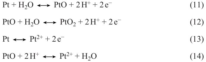
During the anodic polarization, the initial oxidation of the platinum surface between 0.8 and 0.9 V (vs. SHE) is due to the adsorption of OH− (single-electron process) or the direct adsorption of O2− (two-electron process). When coverage of the surface by oxygenated species is below the critical value, the enthalpy of formation of the chemisorbed phase exceeds the enthalpy of formation of the bulk oxide. As the surface coverage by oxygenated species approaches the critical value, the repulsive interactions between the adsorbed oxygen atoms gradually decrease the enthalpy of chemisorption until it becomes equal to the enthalpy of oxide formation. When the critical coverage by oxygenated species is exceeded, the repulsive interactions in the close-packed electronegative O2− adsorption layer induce the occupation of more energetically favourable subsurface sites. In other words, the downward shift of the Fermi level caused by anodic polarization is first counterbalanced by electrons provided by the adsorbed oxygenated species, but later the Pt – O dipole is reversed. Analysis presented by Angerstein – Kozlowska et al.[90] suggested that the full coverage by OH– species is attained at approximately 1.1 V (vs. SHE). Topalov et al.[87] noted the following. The fact that the thermodynamically predicted potential of the electrochemical dissolution of Pt is in the same range as the oxidation potential [E 0 = 1.19 V (vs. SHE)] suggests that electrode processes are determined by the equilibrium between the dissolution of the reduced Pt species [reaction (13)], surface passivation [reactions (11), (12)], and chemical dissolution of Pt oxide [reaction (14)]. However, the Pt dissolution as a whole is a transient process, which nearly stops as soon as the potential becomes constant, which strongly argues against dissolution being controlled by a single reaction equilibrium.
Sugawara et al.[88] also noted that under electrochemical treatment, the dissolution dynamics depends on the character of the applied potential. Indeed, using inductively coupled plasma mass spectrometry (ICP-MS), it was shown that under potentiostatic conditions, dissolved Pt ions are detected at potentials above 0.8 V. The dissolution has a maximum at E = 1.1 V and is suppressed by the formation of 1 – 2.5 Pt – O monolayers at E ≥ 1.2 V. During the potential cycling, the dissolution of Pt is enhanced when the upper potential limit is above 0.8 V and the lower potential limit is less than 0.6 V, where Pt – O is completely reduced. The dissolution is accelerated as the upper potential limit shifts towards more positive values and during the anodic sweep of potential cycling even despite the fact that more than one Pt – O monolayer is formed; this differs from the potentiostatic conditions. The reductive dissolution of PtO2 also takes place in the cathodic cycling. A mechanism of Pt dissolution in the potentiostatic mode and in the potential cycling mode in sulfuric acid was proposed. According to this mechanism, platinum oxide is periodically formed and reduced. The dissolution enhancement may be related to the beginning of the exchange of positions between Pt and O atoms. The dissolution of platinum oxide exposes the platinum metal surface, which is again oxidized. The dissolution of platinum takes place only when the lower potential limit is below 0.6 V (the potential at which Pt – O is reduced to Pt). Thus, acceleration of Pt dissolution as a result of potential cycling requires an exposed Pt metal surface.
Ostwald ripening (Fig. 15) is considered to be the prevailing process for the growth of Pt nanoparticles on the cathode.[91-94]
![[{"id":"3eJkvXxzoT","type":"paragraph","data":{"text":"Schematic picture of the Ostwald ripening of platinum nanoparticles."}}]](/storage/images/resized/0QGmKYgKoQbs6DM2FFkJxkqOFYhaYtWi0KRZ5IWZ_xl.webp)
This process includes the dissolution of smaller Pt nanoparticles, diffusion of dissolved Pt species [most likely, as Pt2+(sol) or its complex with H3PO4] towards larger and more stable Pt particles where the Pt2+(sol) species crystallize [95-98] (see Fig. 15). The driving force of this process is the difference between the electrochemical potentials of nanoparticles, which is affected by particle diameter, the state of the surface, and the electrode potential.[99-101] The dissolution of Pt is the critical stage in the Ostwald ripening mechanism. The reactions occurring in the system can be depicted in the simplified form as the following equations (C 0 stands for the standard concentration; the thermodynamic parameters refer to 25°C).
The catalyst degradation is a complex multifactorial process. The published papers note the dependence of the test results on the testing procedure. A study of aging heterogeneities arising during the operation of PEMFC under start-up and shut-down conditions [102] showed that the degradation mechanism found in this study would not have been observed if MEA had been aged after a standard stress test (potential cycling in nitrogen atmosphere). This raises the question of whether the standardized DOE stress test procedure is applicable to mimic the real operation of FCs. Since platinum is a polyvalent metal (existing in compounds in various oxidation states) able to form a number of different oxides with different equilibrium electrode potentials, then the testing procedure including the magnitude and the order of applied potentials influences the results of testing.
Zago et al.[103] reported experimental results that indicate that the decrease in the specific activity with time does not depend on the aging or size of Pt nanoparticles. Nevertheless, linear sweep voltammetry, which is used for the reduction of platinum oxide and for diagnosing the oxide composition, shows that the composition varies in correlation with the morphology and aging of the catalyst. It was found that the formation of platinum oxide that occurs at 0.61 V (vs. SHE) decreases the catalyst specific activity to a greater extent than platinum oxides formed at higher potentials. This indicates that the loss of catalyst performance due to the formation of platinum oxide depends on the oxide composition.
Speder et al.[104] investigated the influence of the Pt to carbon ratio on the degradation of Pt-based catalysts of PEMFC. With the aim to ensure a systematic study, the authors used a recently developed approach based on the colloidal synthesis of catalysts with identical Pt nanoparticles, but with different Pt contents. The authors used two different commercially available carbon supports, Vulcan XC-72 and Ketjenblack EC-300. The effect of the platinum content on the decrease in ECSA was evaluated by using AST, which simulated the load cycles in PEMFC and start-up/shut-down conditions. In the simulation of load cycles, no evident effect of the Pt loading on the decrease in ECSA is observed, while the simulation of the start-up/shut-down conditions showed that the decrease in ECSA becomes more pronounced with increasing Pt loading.
Analysis of the scientific publications provides a number of important conclusions concerning the corrosion behaviour of platinum in PEMFC electrodes.
The corrosion of platinum is a complex multistage process. The dissolution of platinum proceeds through the formation of intermediate oxide compounds. An increase in the acidity of the medium promotes platinum oxidation and dissolution. During the electrochemical action, not only the magnitude and duration of the applied potentials play a crucial role, but also the character of the potential variation with time is important.
Due to the complexity of the corrosion behaviour of platinum and the overlap of corrosion processes of particular components, it is important to study this behaviour in various electrode structures and under various electrochemical conditions, because this gives rise to additional factors that are difficult to take into account in advance.
4.3. Stabilization of the catalyst support
Carbon corrosion considerably affects the stability of the catalyst support material and, hence, the durability of operation of an electrochemical device.[78] Hence, to increase the lifetime of FCs, it is important to stop the corrosion of the carbon support.
The following methods and approaches were proposed to increase the lifetime of the catalyst support: the use of graphitized carbon black, CNFs, CNTs, reduced graphene oxide (rGO), or nitrogen-doped carbon materials as supports; the use of non-carbon materials such as metal oxides, metal carbides, or silicon; the addition of functional and structuring additives to the support (Fig. 16).[105-120]
![[{"id":"O5sMvvdC-F","type":"paragraph","data":{"text":"Sorts of catalyst support materials."}}]](/storage/images/resized/ChDCfJMiG5Hcx3pBBaUEEOcpkTMPqtdUDJxVQKVL_xl.webp)
4.3.1. Carbon catalyst supports
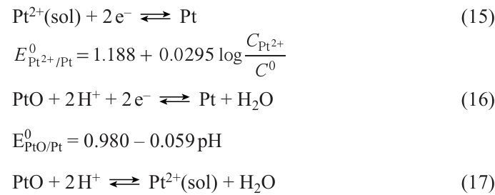
Data on structurally diverse carbon supports and their chemical modifications have been reported in the literature.[105-109][117] Pan et al.[110] investigated graphitized carbon black support [111] in an argon atmosphere at high temperature (1600 – 2200°C). Graphitized carbon-supported platinum nanoparticles (Pt/GC) were used as high-strength catalysts in 1 kW PEMFCs. The accelerated degradation tests carried out using various half-cell and single cell protocols indicated that the Pt/GC catalysts have higher durability than the commercial Pt/C catalysts. After 458 h of dynamic durability testing, the PEMFC stack showed a decrease in the voltage at 1000 mA cm–2 of 5.3% and 85 μV h–1. However, the structure and size of the Pt/GC catalyst and ECSA of the catalytic layer virtually did not change after 458 h, which attests to the excellent stability of the catalyst and MEA under these conditions. In this case, this additionally confirms that the Pt/GC catalyst enables the practical application of PEMFCs.
The review by Stenina et al.[112] addresses the main causes for changes in the properties of materials and the effect of the catalyst support on the electrochemical properties in FCs. The authors noted that the use of CNT or CNF support increases the catalyst performance and durability and decreases the sensitivity to carbon monoxide. Meanwhile, the authors emphasized that materials based on metal oxides such as titanium and tin oxides are promising as electrocatalyst supports. The advantages of these supports are higher stability in an oxidative environment and their promotory effect in the oxygen electroreduction or methanol and CO oxidation reactions. The Pt/CNF catalyst demonstrated [113] a 3% decrease in the power after 1000 AST cycles, whereas the power decrease in the case of conventional Pt/C catalyst was 36% under the same measurement conditions. The catalyst representing CNT-supported platinum nanowires (NWs) demonstrated[114] a power decrease of 20% after 5000 AST cycles; in the case of Pt/C, the decrease in the power was 63% under the same conditions.
Graphene is also used as a catalyst support.[98][115][116] Graphene has a high specific surface area, which allows for efficient distribution of catalyst particles. In addition, graphene is resistant to corrosion and chemical degradation, which increases the durability of the catalyst. Indeed, ECSA of the Pt(19.3%)/graphene catalyst was three times as high as that of the commercial Pt(20%)/C catalyst.[110] After 4000 ADT cycles, the SA and MA values decreased by 40%, which attests to higher stability of this catalyst, especially in the electrochemical reduction of oxygen, unlike commercial catalysts, the loss of activity of which reached 60%.
An important line of research in this field is nitrogen doping of the carbon support.[118] The introduction of nitrogen atoms into carbon increases the catalytic activity and the strength of bonding between the catalyst particles and the support, which reduces agglomeration of platinum nanoparticles and their leaching during operation. The hybrid Pt/NC catalyst showed [113] a markedly higher stability than the Pt/C catalyst. After 50 h of AST, the power of the Pt/NC catalyst decreased by 19%, while in the case of Pt/C, this decrease was 34%.
Table 3[95][113-116][119][120] presents comparative analysis of various methods for stabilization of the catalyst support using carbon materials and their modifications. The table includes the results of studies of series of samples using various AST or ADT procedures. The key parameters for evaluation of the stabilization methods were power and ECSA measured under identical conditions before and after the durability tests.
4.3.2. Non-carbon catalyst supports
As has already been mentioned, an important problem of using Pt/C electrocatalysts in low-temperature FC is that they undergo degradation because of oxidation of the carbon support.[83][121] A promising way for increasing the stability is to use oxidation-resistant non-carbon supports[122-131] such as oxides of some metals in higher oxidation states. Titanium dioxide has its own catalytic activity in the oxidation of organic compounds. In addition, TiO2 is resistant to oxidative corrosion, because titanium is in the highest oxidation state. The use of TiO2 as a catalyst support has been described in a number of publications.[100][109][110] [132][133] Volochaev et al.[121] synthesized TiO2 with a specific surface area of 104 m2 g–1, which was used as a support for the platinum catalyst. For the Pt/TiO2 and Pt/TiO2 samples with graphitized carbon black (Pt/TiO2 – C), platinum ECSA were measured to be 26 m2 g(Pt)–1 and 44 m2 g(Pt)–1, respectively. The materials proved to have much higher stability than the commercial Pt/C catalysts. The decrease in ECSA after 1000 cycles was 23% for Pt/TiO2 and 25% for Pt/TiO2 – C; meanwhile, this value for commercial Pt/C is 73%. Using electrooxidation and dispersion of metals, Kubanova et al.[134] prepared a series of Pt/TiO2 – C catalysts containing cube-shaped platinum particles of 6.7 nm size uniformly distributed on the hybrid TiO2 – C support containing hydrated titanium dioxide as anatase. The electrooxidation of dimethyl ether on the obtained catalysts and commercial Pt/C catalyst E-TEK was studied by CV, chronoamperometry, and using rotating disk electrode (RDE). The authors noted high activity of platinum catalysts containing hybrid TiO2 – C support, exceeding the activity of the commercial catalyst by more than an order of magnitude, and demonstrated the prospects of using these catalysts to increase the efficiency of direct dimethyl ether FCs.
Titanium dioxide is promising as a catalyst support, as it has high corrosion resistance; however, moderate electrical conductivity of TiO2 may have an adverse effect on the catalyst performance. Doping with n-type conductors the atomic radius of which is similar to that of Ti increases the concentration of free electrons and shifts the Fermi level towards the conduction band, thus increasing the electrical conductivity of TiO2 . Niobium in the pentavalent ionic state is used most often as the n-type dopant. Kim et al.[127] proposed niobium-doped titanium dioxide as the support. The Pt/Nb – TiO2 catalyst had a higher MA value before and after AST on RDE and a higher Pt ECSA retention compared to the Pt/C catalyst.
Zhou et al.[135] synthesized zirconium-doped cerium oxide particles (Ce0.8Zr0.2O2) as a doping additive to the catalyst to improve the chemical stability of MEA. After 264 h of AST under OCV, this catalyst provided a decrease in the peak power by only 6%, whereas the Pt/C catalyst showed a decrease in the peak power by 44%. In addition, the hydrogen crossover through the membrane in MEA containing Ce0.8Zr0.2O2 proved to be more than twice lower after 264 h of AST than that in standard MEA after 75 h of AST.
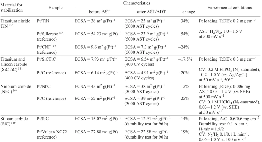
The Pt catalyst supported on Sb-doped SnO2 (ATO) was stable[121] to a decrease in Pt ECSA, while the MA and SA losses were higher than those for the conventional Pt/C catalyst. During the conduction of AST, the carbon support proved to be insufficiently strong, as indicated by the large-scale detachment of Pt nanoparticles (Fig. 17a). Conversely, Pt nanoparticles were not detached from the ATO support (Fig. 17b). However, AST was accompanied by the formation of a core–shell structure, with the Sb content in the core being close to the initial one and that on the surface being lower than the initial one (see Fig. 17b). The authors attributed the low catalytic activity of the proposed catalyst to the decrease in the surface concentration of Sb during AST.
Titanium nitride TiN is a promising material owing to the nitrogen vacancies present in its structure, which generate highly favourable sites for Pt deposition accompanied by the formation of strong Ti – Pt bonds.[136] The strong interaction can result in lowering of the Pt 5d level, which causes increase in the catalyst activity towards the oxygen reduction reaction (ORR). The TiN catalyst was deposited directly on GDL. The obtained catalyst showed a markedly higher performance than Pt/C (E-TEK), with high stability of operation being retained. Moreover, it was demonstrated that TiN can be used in the MEA design without an ionomer.
Transition metal carbides constitute a promising group of materials for catalyst supports, because along with high corrosion resistance, they possess a reasonable electrical conductivity and mechanical strength.[137]
Transition metal carbides such as TiC, TaC, NbC, and WC were investigated for characteristics of the adsorption of a Pt overlayer and for the oxygen adsorption energy on the deposited Pt overlayer. A set of carbides (TiC, NbC, TaC, WC, and SiC) was studied using the density functional theory. The calculated adsorption characteristics of the carbides towards Pt layers indicated that the adsorption of platinum on these transition metal carbides is thermodynamically favourable.[138][139]
The supports most studied for PEMFC applications are WC, SiC, and TiC.[107-116][140] Extensive studies of a new thermally stable support made of the binary SiCTiC carbide for PEMFCs have been reported.[141-143] The electrochemical activity of Pt/SiCTiC is sensitive to the content of TiC.[141-143] Recently it was proved that niobium carbide supports are more stable than the conventional supports used in Pt/C catalysts.[144] It has been reported that transition metal carbides in combination with nitrogen-doped carbon make more stable electrocatalysts for the oxygen reduction and hydrogen evolution reactions.[145] Similarly, tungsten monocarbide nanoparticles on multi-walled CNTs were used as co-catalysts for the synthesis of active Pt-WC/CNT platinum electrocatalysts.[143] The Pt-WC/CNT catalyst showed a higher power density than Pt/CNT. The maximum power density of Pt-WC/CNT was 0.504 W cm−2, which is 1.1 times higher than that of the Pt/CNT catalyst with a power density of 0.458 W cm−2. The material based on activated zirconium carbide intercalated into the Vulcan carbon black makes an excellent support for Pt, since it not only stabilizes the Pt nanoparticles, but also stimulates the ORR activity.[119]
The first study of zirconium carbide as a corrosion resistant support to replace carbon in the Pt electrocatalyst was reported by Thakare and Masud.[132] Commercial ZrC (with a specific surface area of 1 m2 g–1) was activated using solid sodium carbonate, which gave activated ZrC with a large surface area (a-ZrC, 134 m2 g–1). Both ZrC and a-ZrC showed good corrosion resistance during carbon corrosion tests. In the Pt/ZrC and Pt/a-ZrC electrocatalysts, the loss of electrochemically active surface of platinum was less than 40% after AST. The Pt/ZrC catalyst did not show a considerable shift of the initial potential in the linear sweep voltammetry after start-up and shut-down protocol tests. The shift of the E1/2 potentials of the Pt/ZrC and Pt/a-ZrC catalysts was 13 and 24 mV, respectively, which is smaller than 30 mV for Pt/C. Computer analysis revealed strong interaction between ZrC and Pt (platinum adhesion to the support), which is responsible for the durability of the catalyst due to higher dissolution potential. Thus, strong interfacial interaction in these electrocatalysts is favourable for stabilization of the catalytic properties of platinum. Table 5[146][147] presents a comparative analysis of various stabilization methods for the catalyst supports based on using various non-carbon materials. The tables includes the results of AST and ADT studies of series of samples. The key parameters used to evaluate stabilization methods include power, ECSA measured by CV (and ECSA retention rate), and SA and MA measured under identical conditions before and after the durability tests.
4.3.3. Structural modification of the support
In the modelling of FC catalytic layers, the pore structure is an important characteristics, since supply of the reactants (hydrogen, oxygen, or air) and withdrawal of water are accomplished through the pores. Therefore, a number of studies address the influence of the pore structure of the support on the FC service life.
Lazaridis et al.[148] reported the results of stability studies for three structures: (1) microporous (Pt/Vulcan), (2) bottlenecked mesoporous (Pt/Ketjenblack), (3) and non- bottlenecked mesoporous structures (modified Pt/Ketjenblack). The non-bottlenecked mesoporous support provided not only high power but also, good operation stability with only 35% loss of the maximum power after 50000 AST cycles, whereas the conventional catalyst (Pt/Vulcan) lost 52% of the power after 10000 AST cycles (Table 7).
Nechitailov et al.[68] reported the results of studying the stability of highly porous electrodes containing CNTs. Highly porous electrodes were superior in the stability to conventional Pt/C electrodes: 76% vs. 87% power loss after 10000 AST cycles (see Table 7).
A number of papers [68][149-154] describe the principles of fabrication of electrode structures with spatially mismatched Pt/C and Nafion components by introduction of multi-walled CNTs with a large aspect ratio into the electrode material and formation of the island structure of the Nafion polymer. This technique made it possible to increase the degree of utilization of the surface of platinum nanoparticles and to increase the particle stability.
Fig. 18 presents the main causes for the degradation of the catalyst support and possible stabilization methods. It is noteworthy that the listed stabilization methods are meant to eliminate several causes of degradation at once. The listed materials combine, most often, several stabilization pathways.
![[{"id":"ryAcjD_how","type":"paragraph","data":{"text":"Main causes for degradation and stabilization methods of the catalyst support."}}]](/storage/images/resized/D8TKjEC5ecU85srdFCvUte2pZXaQVGy3qElc41II_xl.webp)
Thus, the catalyst support plays a multiple role in both the efficiency and durability of an electrochemical system. The own catalytic properties of the support in combination with high surface area lead to higher catalyst activity. The use of oxidation-resistant electron-conducting materials makes it possible to stabilize the catalyst as a whole and prolong the catalyst durability. The interfacial interaction between the catalyst components decreases the energy of the system and increases the durability due to the mechanical and chemical stability.
4.4. Stabilization of the metallic particles of the catalyst
Stabilization of the proper metallic particles of the catalyst is addressed in numerous publications. The stabilization methods are schematically depicted in Fig. 19. Promising approaches to stabilization of catalyst particles include alloying of platinum, development of intermetallic catalysts, core – shell structures, and porous metal structures, replacement of Pt with other metals, and introduction of additives into the catalyst.
![[{"id":"D2AstQwgdb","type":"paragraph","data":{"text":"Key methods for stabilization of metal particles of the catalyst."}}]](/storage/images/resized/1YfmLJ1jSxVzCE8N6Ie3rxyS7Y7pS8igoE7xOhIB_xl.webp)
The enhancement of the interaction between metal nanoparticles and supports is an effective approach to increasing the stability.[155] The stability of Pt-based catalysts has markedly improved in recent years, but this is still a great problem for commercialization of Pt-based catalysts.
4.4.1. Alloying of platinum
Alloying of Pt with transition metals (Co, Ni, Fe, Y, Sc, Gd, etc.) is a method for producing active and durable catalysts.[156-159]
The addition of transition metal atoms with smaller atomic radii decreases the bond strength between Pt and oxygen-containing compounds and thus increases the ORR activity.[160][161]
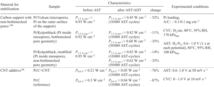
Fig. 20 shows[160] the L10 – Pt2CuGa nanoparticles in which the PtCuGa alloy has covalent atomic interactions between Pt and Ga. These interactions enhance the structural stability of the catalyst and its efficiency in ORR, making it a promising material for PEMFC applications.
![[{"id":"WRu-MaCB7h","type":"paragraph","data":{"text":"L1<sub>0</sub> – Pt<sub>2</sub>CuGa nanoparticles with Pt – Ga covalent atomic interaction as PEMFC catalysts.[[ type=\"anchor\" referenceId=\"13549\" ]]"}}]](/storage/images/resized/qaXxNi9oh9xrctKtdR6ppKh7uxLRNETMQS0WpPdp_xl.webp)
Kim et al.[162] studied binary PtFe metal catalysts. The authors proposed a cathode nanocatalyst made of the PtFe alloy with a carbon protective layer and a chemically ordered cathode, which showed high activity and stability and effective utilization of platinum. The synthesized catalyst with the highest degree of phase transition to chemically ordered PtFe had a mass activity of 848 A g(Pt)–1 at a potential of 0.9 V on RDE, with the performance being maintained for 30 000 stability test cycles. PEMFC with this catalyst produced a stable current of 0.8 A cm–2 at 0.66 V (1.1 A cm–2 at 0.6 V) during 30 000 cycles of stability testing for an ultralow total Pt loading of 0.100 mg cm–2; this far exceeds the 2025 DOE stability target.
Ramaswamy et al.[158] investigated PtCo alloy catalysts with Pt-enriched compositions in order to decrease the amount of dissolved Co and mitigate the harmful effect of Co during the operation. The authors noted that the use of both Pt5Co and Pt7Co catalysts leads to a pronounced decrease in the voltage loss in the cell compared to the existing Pt3Co catalyst (by ~ 50 mV and ~ 100 mV, respectively, after the 30 000 AST cycles). Despite the fact that the Pt/C catalyst is, as expected, more durable than all of the tested PtxCo alloys, the improved initial kinetics of ORR in the case of PtxCo leads to higher voltage in the initial operation period in the low current density region.
The stability of the PtNi catalyst supported on various carbon materials has been studied on RDE and in MEA.[163][164] A two-layer structure consisting of an active layer (PtNi/C) and buffer layer (Pt/C) demonstrated[159] an excellent stability: the peak power decreased by only 3.6% after 10 000 AST cycles, whereas in the case of Pt/C, this decrease was 6.3%. Payattikul et al.[163]discussed the PtNi catalysts on various carbon supports. The accelerated durability test of these catalysts showed that the PtNi/Ketjen black had a better ORR stability than PtNi/Vulcan XC-72R or PtNi/graphene. After 4000 cycles of ADT, SA and MA decreased by 15.9% for PtNi/Ketjen black, by 25.0% for PtNi/Vulcan XC-72R, and by 28.7% for PtNi/graphene.
A study of the hybrid PtPd catalysts on nitrogen-modified carbon composite (NC) by accelerated stress testing of FC demonstrated that Pt3Pd1/NC and Pt/NC have much higher stability and mass catalytic activity than Pt/C catalysts: after 30 000 cycles, the degree of catalyst degradation was 18.7% for Pt/C, 5.3% for Pt/NC, and 1.2% for Pt3Pd1/NC.[113]
The PtAu alloy on TiO2 nanowire with a carbon shell demonstrated an enhanced stability and catalytic activity compared with the traditional Pt/C catalyst.[165] ECSA of the PtAu alloy decreased after ADT by 20%, while that of Pt/C decreased by more than 40%. The current density of the alloy remained invariable, whereas in the case of Pt/C, the Pt particle size increased and ORR performance decreased.
Gao et al.[166] analyzed the effect of Mo and Au dopants in the PtNi catalyst. It was found that the Mo dopant mainly suppresses the external diffusion of Ni atoms, whereas Au stabilizes the surface layer of Pt, thus preventing dissolution. The PtNiMoAu catalyst showed high activity and durability, which surpass the 2025 DOE technical targets.
Thus, the main goals of alloying Pt catalysts are to increase the catalytic activity, improve the catalyst stability, and, hence, reduce the catalyst costs.
4.4.2. Design of intermetallic compounds
Atomically ordered intermetallic compounds with a fixed stoichiometric ratio and highly ordered atomic structure are attracting increasing attention of researchers. In an ordered intermetallic electrocatalyst, atoms of each element are arranged in a definite crystallographic order and are linked to one another by strong d-orbital interactions.[167-169] Intermetallic compounds have higher strength and higher corrosion resistance than solid solution alloys owing to lower enthalpy of formation and stronger interatomic interactions.
Zhao et al.[170] studied PtFe intermetallic compound with enhanced ORR characteristics. After 30 000 AST cycles on RDE, the catalyst based on the PtFe intermetallic with L12 unit cell supported on nitrogen- and sulfur-doped carbon (L12 – Pt3Fe/Fe-SNC) showed a decrease in MA by 19% (the MA decrease for the Pt/C catalyst was 59%), which means that the PtFe intermetallic-based catalyst has a much higher durability than the conventional catalyst. In addition, the power density in single PEMFC cells was higher for this catalyst (P0.4 V = 1.547 W cm–2) than for Pt/C (P0.4 V = 1.108 W cm–2).
The L10 – Pt2CuGa/C catalyst with a unique Pt – Ga covalent atomic interaction provided[171] a high ORR activity and stability in the FC cathode [MA = 0.57 A mg(Pt)−1 at 0.9 V, with a peak power density of 2.60/1.24 W cm−2 in H2 – O2/air and the voltage loss of 28 mV at 0.8 A cm−2 after 30 000 cycles). Theoretical calculations predict enhanced adsorption of oxygen intermediates on the L10 – Pt2CuGa surface, with the increase in the durability being attributable to the formation of stronger Pt – Ga covalent interactions.
4.4.3. Core – shell structures
The use of structural factor via thorough adjustment of the thickness of Pt shell in core – shell structures increases the corrosion resistance of platinum due to the creation of a strong electron bond between the Pt shell and core.[172-174]
Jiang et al.[175] developed a catalyst composed of Pt@Pt3Ti with atomically controllable shell as a result of precise thermal diffusion of Ti into Pt nanoparticles to provide effective and durable ORR. The Pt@Pt3Ti/TiO2 – C catalyst has high MA, which decreased by only 2% after 30 000 AST cycles, which is almost 19.5 times lower than this value for commercial Pt/C.
A core – shell structure with a Pd core coated by a Pt shell was reported by Hong et al.[176] The peak power density of the electrode reaches 0.62 W cm−2 for Pt loading of 19 μg cm−2, which is higher compared to a conventional electrode (0.55 W cm−2) with Pt loading of 100 μg cm−2. The degradation rate of the peak power density of the electrode was only 4.8% after 30 000 cycles of AST, which demonstrates a better durability compared to the Pt/C electrode.
It was shown[172-177] that the introduction of non-metals into the core may increase the stability. Due to high electronegativity, non-metal elements (such as P, N, etc.) have a very high affinity to Pt, which helps to inhibit the Pt dissolution.
Li et al.[177] proposed a catalyst based on the BPd alloy, which has a 14 times higher MA towards ORR than the conventional Pt/C-based catalyst. Although the loss of activity during ADT was faster for BPd/C than for other catalysts, the mass activity of this catalyst after 3000 ADT cycles was four and five times higher than those of Pd/C and Pt/C, respectively.
4.4.4. Design of porous metal nanostructures
An approach to increasing the stability of metal particles is to eliminate the catalyst support and design porous all-metal nanostructures. The method involves fabrication of a 3D porous structure with a large surface area, which contains numerous active sites and facilitates the mass transfer. In addition, the large surface area leads to some suppression of the general degradation processes in Pt-based nanoparticles such as nanoparticle migration, dissolution, and Ostwald ripening.[79][178] The most studied unsupported metal nanostructures include noble metal-based aerogels, multimetallic meso/nanostructured films, and template-based metal nanostructures.[179]
Exceptional ORR activity and durability were found for the AuCu aerogels,[180] which became a promising alternative to the Pt-based catalysts in FC applications. For example, ECSA of the Au52Cu48 aerogel decreased by only 2.6% after 10 000 ADT cycles, whereas in the case of Pt/C, this decrease was 53.3%.
Shi et al.[181] reported the ternary metal aerogel Au@Pt3Pd with a unique core–shell dendrite structure as a catalyst (Fig. 21). The Au@Pt3Pd catalyst possessed excellent electrochemical characteristics [MA = 812 A g(Pt + Pd)–1], much exceeding those of commercial Pt/C [MA = 412 A g(Pt)–1]. In addition, the durability of this catalyst was at the same level at that of Pt/C: ECSA of the Au@Pt3Pd aerogel decreased by 21% after 5000 ADT cycles, which is comparable with this value for Pt/C (23.7%).
4.4.5. Replacement of Pt with other metals
The modern studies of PEMFC pay considerable attention to alternative catalysts based on other metals instead of platinum.
The Fe – N – C catalysts are promising alternatives to Pt/C for the use in PEMFC because of their activity and lower cost. However, Fe – N – C are inferior to Pt/C in the stability: after 30 000 AST cycles in H2/N2 , the activity decreases by 48%, while the performance at 0.8 V decreases by 50%.[182]
Gold is also used as a catalyst for PEMFC, which is due to its high corrosion resistance. An rGO-based composite material with gold nanoparticles deposited by a microwave-assisted process (Au/rGO) was used as the PEMFC cathode and subjected to durability tests.[183] A 7.5% decrease in the power density was detected. Furthermore, the initial power characteristics of Au/rGO were 20% higher than those for Pt/C (0.55 W cm–2).
4.4.6. Introduction of additives into the catalyst
One way for stabilization of the cathode catalyst is the use of additives promoting recombination of radicals. Kim, et al.[184] deposited cerium oxide (CeOx) on a platinum catalyst by the plasma-enhanced atomic layer deposition process; this increased the catalyst stability in PEMFC, which was indicated by the change in the peak power density after 30 000 AST cycles: the decrease in the power density for Pt/CeOx was only 25% (for comparison, this value for Pt/C was 40%). In PEMFC, free radicals impair the catalyst performance and stability. CeOx acts as a free radical scavenger through the redox reaction of Ce3+/4+ ions and prevents the oxidative action of hydroxyl and hydroperoxyl radicals resulting from the reaction between hydrogen peroxide and the released cations. The authors note that stability increase resulting from the plasma-enhanced atomic layer deposition and CeOx encapsulation can be considered to be a promising strategy for PEMFC catalysts.
Tao et al.[174] reported the results of stability testing for the catalyst made of Pd/Pt(core – shell) nanowire with added PdAu (Pd/PdAu/Pt) (Fig. 22). The developed catalyst showed only 7.8% loss of ORR mass activity after 80 000 AST cycles without dissolution of the Pd core and good stability of the core – shell sandwich nanostructures. This was a considerable enhancement of the electrocatalytic stability compared to the Pd/Pt NW core – shell structures for which the loss of MA was 83% after 50 000 AST cycles.
4.4.7. Spatial (structural) stabilization of metal nanoparticles
A promising line of research that deserves close attention is the design and use of materials characterized by strong interaction of metal nanoparticles with the support, called strong metal–support interaction (SMSI) materials. Perhaps, one of the first mentions of SMSI can be found in the study by Tauster et al.[185] Since then, this research area has been markedly developed, but by no means exhausted its potential.
Regarding the stabilization issue, the fabrication of SMSI catalysts can be assigned to mixed type of stabilization combining the thermodynamic (modulation of electron energy and chemical bonds) and structural [spatial restriction of the nanoparticle mobility (encapsulation)] types of stabilization.
Examples of spatial (structural) stabilization of metal nanoparticles can be found in the literature.[186-188] The authors used decoration of metal nanoparticles by various porous materials, which gave rise to a spatial (structural) barrier that prevented agglomeration. Using sol – gel process, Vulcan XC-72 carbon-supported platinum (Pt/Cs) meant for the use as a PEMFC cathode was coated with silica layers containing three types of surfactants with different charge properties.[186]
The following three types of surfactants were used in order to prevent agglomeration of Pt nanoparticles and detachment of Pt nanoparticles from the carbon support during operation:
(1) cationic surfactant [cetyltrimethylammonium bromide (CTAB)];
(2) anionic surfactant [sodium dodecylbenzenesulfonate (SDBS)];
(3) nonionic surfactant [Pluronic 123 (P123)].
The degree of stabilization depended on the type of surfactant deposited by the sol – gel method. The silica-coated Pt/C catalyst obtained using SDBS and P123 showed 27.3% and 22.7% durability increase, respectively, after 500 cycles in the cyclic voltammetry test (0.5 M H2SO4). Xu and Huang [187] deposited an ultrathin layer of mesoporous silica modified with cetyltrimethylammonium bromide directly on Pt/C using the Stöber method. The stability of the synthesized Pt/C@SiO2 catalyst was evaluated using an accelerated potential cycling test. The ECSA of the material remained at 90% level, while ECSA for Pt/C decreased to 51%. The TEM images of Pt/C and the modified catalyst before and after the accelerated test (Fig. 23) indicate that the silica coating effectively suppresses Pt aggregation.
![[{"id":"V0azSHqfoC","type":"paragraph","data":{"text":"TEM images and particle size distribution for Pt/C (<i>a, c</i>) and Pt/C@SiO<sub>2</sub> (<i>b, d</i>) before (<i>a, b</i>) and after (<i>c, d</i>) the accelerated test.[[ type=\"anchor\" referenceId=\"13574\" ]]"}}]](/storage/images/resized/TmsrlLevTA40HPAvigaRLY7IJz2IHNDi4Lu1vkKg_xl.webp)
In addition, the coated catalyst exhibited a higher electrocatalytic activity in methanol oxidation than conventional Pt/C. Wills et al.[188] described the use of four commercially available fluorine-containing surfactants (Zonyl FSO, Zonyl 1033D, Forafac 1098, and Novec FC 4430) to improve the surface wetting during the screen printing of carbon black inks on PEMFC electrodes. The fluorinated surfactants were tested in inks containing a solution of Nafion® ionomer with platinum-coated carbon black and were evaluated for electrochemical activity (by cyclic voltammetry), leaching, and ability to form ink layers. Good wetting characteristics were observed, and the ink showed the same specific ECSA [200 – 430 cm2 mg–1(Pt)] as the standard reference ink [370 cm2 mg–1(Pt)], indicating that the surfactants are not adsorbed on the Pt surface and do not block the adsorption/desorption of hydrogen. In addition, it was shown that fluorinated surfactants in the cured inks are electrochemically inert in the potential range required for FC operation.
Table 8 presents comparative analysis of various methods for catalyst stabilization. The table includes the results of studies of series of samples using various AST or ADT tests. The main parameters used to assess the efficiency of stabilization methods include power, ECSA measured by the CV method, and SA and MA measured under identical conditions before and after the durability test.
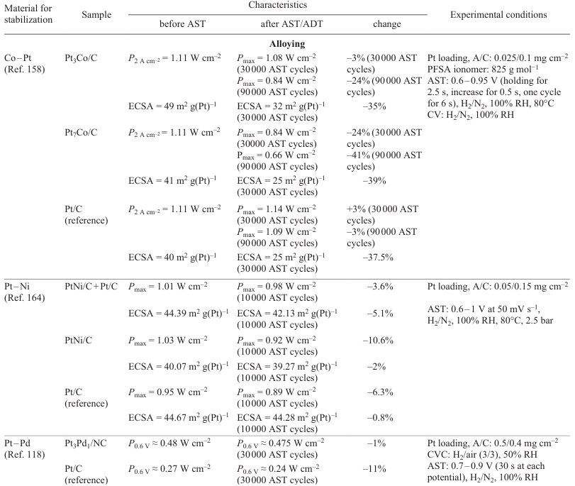
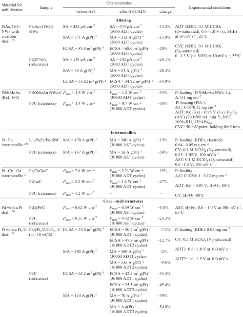
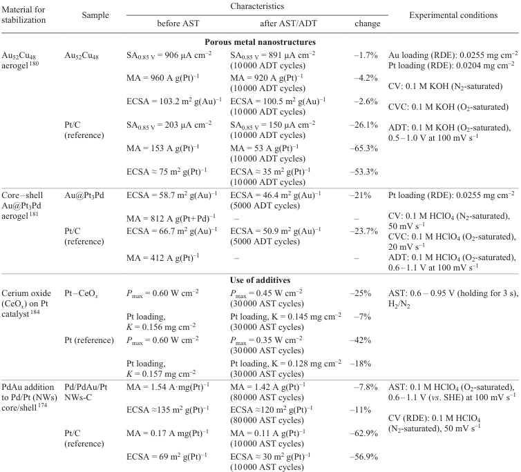
Fig. 24 summarizes the key causes for metal particle degradation in the catalyst and possible stabilization methods. Most methods are directed against several causes of degradation.
![[{"id":"cLnHc17oex","type":"paragraph","data":{"text":"Main causes for degradation and methods for stabilization of metal particles in the catalyst."}}]](/storage/images/resized/UyotYgjP1W7Ls5bB9WHbBoe4thpWy1DfqC0a2uw2_xl.webp)
Thus, metal particles of the electrocatalyst are subjected to a significant corrosion load because of electrochemical reactions involving reactive species (radicals, ions, molecules) that take place on their surface. The stabilization problem is solved along three main lines: thermodynamic, kinetic, and structural stabilization. The first line implies the decrease in the chemical potential by the preparation of intermetallic compounds, doping, or interfacial interaction with the support. The second one includes the addition of scavengers for the most reactive radicals. The third line is actually a combination of the spatial isolation of a part of the metal from the harsh environment with reduction of the potential energy of the system (core – shell structures).
The use of unsupported catalysts is a sort of returning back (e.g., Raney nickel); nevertheless, this approach may also be useful for increasing the stability.
4.4.8. Strong metal – support interaction
The main approaches to the design of materials with strong interactions of metal nanoparticles with the support were described by Chen (Fig. 25, Fig. 26, Fig. 31).[189] The main principles and results of this stabilization are analyzed in more detail below. The strong metal – support interaction is generated in two ways: adsorption and formation of surface chemical compounds.
It is important to note that this stabilization technique is based on the decrease in the chemical potential of the system. This system is less prone to chemical reactions because it has higher potential barriers for particular reactions compared to the non-stabilized system.
4.4.8.1. Oxidative strong metal – support interaction (O-SMSI)
Oxidative strong metal–support interaction (O-SMSI), a new method for the generation of SMSI by high-temperature oxidative treatment, was first described for the Au/ZnO nanorod catalyst [190] (Fig. 25). The structural and spectroscopic characteristics of the obtained system attest to strong metal – support interactions between gold nanoparticles and ZnO nanorods. The catalyst showed encapsulation of gold nanoparticles into ZnO and electron transfer between gold and the support.
4.4.8.2. Adsorbate-mediated SMSI (A-SMSI)
Whereas the O-SMSI method is based on high-temperature heat treatment (≥ 500°C) of the catalyst, which is inevitably accompanied by a decrease in the catalytic performance because of blocking of the active metal, the adsorbate-mediated SMSI method (A-SMSI) makes it possible to obtain catalysts at lower temperatures.[191] The strong metal – support interactions between Rh nanoparticles and TiO2 and Nb2O5 oxide supports at a relatively low temperature (150 – 300°C) were characterized by in situ spectroscopy and microscopy are attributed to the presence and influence of the strongly bound adsorbates (HCOx) on reducible oxide supports (TiO2 and Nb2O5), which induced the formation of oxygen vacancies in the support and encapsulation of Rh nanoparticles in the support (Fig. 26, Fig. 27).[189][191] The encapsulating layer is permeable to reactants and stable under reaction conditions, and it strongly influences the catalytic properties of Rh, which allows for rational and dynamic control of the CO2 reduction selectivity.
4.4.8.3. Wet chemistry SMSI (wcSMSI).
This is a mild method for the generation of the strong metal–support interactions requiring no elevated temperatures. As noted above, A-SMSI provides encapsulation at relatively low temperatures, but the wcSMSI method gives rise to strong interactions in aqueous solutions at room temperature. Using this method, one not only avoids the traditional high-temperature redox process, which induces the initial sintering of metal nanoparticles, but also effectively protects metal nanoparticles from oxidation. For example, Zhang et al.[192] reported the Au/TiO2-wcSMSI catalyst, which was obtained by redox reaction of Auδ+ and Ti3+ precursors in aqueous solutions. The presence of strong interaction was confirmed by coating of Au nanoparticles with a TiOx layer, electron interaction between Au and TiO2 , and suppression of CO adsorption on Au nanoparticles. Owing to wcSMSI, the Au/TiOx interface with improved redox properties is favourable for oxygen activation, thus accelerating the oxidation of CO. In addition, the oxide layer efficiently stabilizes Au nanoparticles. Spasov et al.[193] described investigation of structure, morphology, and electrochemical properties of the Pt/C and Pt/x-SnO2/C catalysts synthesized by the polyol method (reduction of platinum with polyatomic alcohols such as ethylene glycol). A series of catalysts supported on SnO2-modified carbon (Fig. 28) was synthesized and studied by various methods including TEM, X-ray diffraction, X-ray photoelectron spectroscopy, electrochemical methods, and testing in MEA. The content of SnO2 varied from 5 to 40 mass %.
![[{"id":"vtCjTvKe0z","type":"paragraph","data":{"text":"Schematic picture of the wcSMSI operation principle. EG is ethylene glycol."}}]](/storage/images/resized/UNZeprsDepLyhZLiZxOG6LkJGaID4fLOx5uhlKzP_xl.webp)
The TEM image and X-ray diffraction and X-ray photoelectron spectroscopy data suggest the formation of Pt/SnO2 heteroclusters (Fig. 29).[193]
![[{"id":"r53HNd6OG0","type":"paragraph","data":{"text":"TEM images and particle size distribution for Pt/SnO<sub>2</sub>(10 mass %)/C at different magnifications.[[ type=\"anchor\" referenceId=\"13580\" ]]"}}]](/storage/images/resized/Gn2j0FIKenhQJnBtqpMaxEid5NVK99gGBBQomLQp_xl.webp)
A content of SnO2 at approximately 10 mass % provides an optimal structure and morphology of the catalytic layer with a uniform distribution of Pt/SnO2 over the carbon support surface. The Pt/SnO2(10 mass %)/C catalyst shows high activity in the ORR and stability in the ASTs caused by high SnO2 stability and pronounced interaction between SnO2 at Pt. The current–voltage characteristics of Pt/SnO2(10 mass %)/C in PEMFCs are comparable with CVC of Pt/C; however, the expected longer durability of the Pt/SnO2 catalyst can be due to higher corrosion resistance of the support (tin oxide), since tin occurs in the higher oxidation state and does not release catalytic poisons, as in the case of carbon (CO).
4.4.8.4. Reaction-induced SMSI (R-SMSI)
It is noteworthy that the above-mentioned types of SMSI methods are mainly based on oxide supports such as TiO2, ZnO, Nb2O5, etc. However, relatively redox-inert supports (e.g., Mg and Al oxide supports) are unsuitable for SMSI, because they are hardly activated on the surface.
The reaction-induced SMSI (R-SMSI) is an effective method to induce activation, migration, and encapsulation of a redox-inert support as a result of phase transition. For example, Deng et al.[165] used electrospinning (method for fibre production by action of electrostatic forces on an electrically charged jet of a solution or a melt) to synthesize a series of 1D platinum – gold/titanium dioxide nanowire catalysts (PtAu/TiO2 NWs) with various Pt : Au : Ti ratios (Fig. 30).
The catalyst microstructure and electrochemical properties for ORR were studied. The results showed parabolic type ORR performance of the PtAu/TiO2 catalysts depending on their composition. The optimized Pt1Au1/(TiO2)1 nanowires had a 4.19 times higher MA and 2.82 times higher surface activity than the commercial Pt(20 mass %)/C catalyst. In addition, the stability test showed that the ECSA of Pt1Au1/(TiO2)1 nanowires decreased by almost 20%, while that of Pt(20 mass %)/C decreased by more than 40% under the same conditions. The high activity of Pt1Au1/(TiO2)1 nanowires can be attributed to the synergistic effect of TiO2 and the durability inherent in Au. In the case of nanowires with higher specific surface area, it was found that the electronic structure of Pt can be changed by neighbouring TiO2, which further decreases the band gap and enhances the catalytic activity.
4.4.8.5. Laser-induced SMSI (L-SMSI)
Yet another approach described in the literature is laser generation of the strong metal – support interaction (L-SMSI) (Fig. 31).[189]
Similarly to wcSMSI, this approach makes it possible to form a catalyst without specific gas atmosphere or heat treatment. Zhang et al.[194] implemented L-SMSI on the Pd/TiO2 catalyst using a photochemical procedure. The laser ablation in a liquid is generally accepted as a versatile, one-stage method for the synthesis of metastable functional nanomaterials with new properties via photoinduced local physicochemical processes.[195-197] In particular, when the excitation energy from UV radiation exceeded the band gap of titanium dioxide (3.1 eV), photoinduced separated reducing electrons (e–) and oxidizing holes (H+) were generated and provided the formation of Ti3+/oxygen vacancy (Ov) species and then Pd – Ov–Ti3 compounds.[189] The L-SMSI surface layer thus formed proved to be able to undergo repeated reduction and oxidation and exhibited activity towards oxygen redox reactions. Similarly, the L-SMSI method was applied to manufacture CeO2-based platinum system catalysts even on non-reducible oxide supports such as Al2O3 and MgO.
Thus, the requirements for an ideal catalyst for ORR include both high activity and stability. Series of classical SMSI-produced systems, including SMSI, O-SMSI, and A-SMSI, provide high ORR stability due to the encapsulation effect. In addition, electron transfer and mass transfer between the metal and the support make the modulation of the catalyst activity more practicable and efficient. Some new types of SMSI, e.g., L-SMSI, wcSMSI, and R-SMSI, are characterized by low synthesis temperatures. The encapsulation strategy and technique can effectively isolate metal nanoparticles and prevent metal detachment from the support and agglomeration, which greatly improves the stability of catalysts.
To summarize the consideration of electrocatalysts for proton exchange membrane devices, one can note three critical components susceptible to attacks during FC operation: metal particles, support, and the metal particle/support interface. Metal particles are subject to several types of degradation including dissolution, agglomeration, and loss of contact with the support.
Supports based on carbon blacks of various morphology are used most often because of their high surface area, the presence of mesopores, and relatively high electron conductivity. However, the catalyst support is subjected to strong corrosive impacts, which leads to structure degradation, loss of contact with metal particles, shedding of particles, and poisoning of the metal component of the catalyst by corrosion products.
The protective measures against the catalyst degradation are correspondingly directed towards the prevention or mitigation of these degradation processes. A distinctive feature of the protective measures is the necessity to maintain the catalyst activity at a relatively high level.
Three main types of catalyst stabilization can be distinguished, that is, thermodynamic, structural, and kinetic stabilization.
Thermodynamic stabilization is aimed at reducing the Gibbs energy of the system by certain technological approaches: production of intermetallic compounds, alloys, various core–shell structures, etc.
For the catalyst support, a fairly popular approach is based on the replacement of carbon with more oxidation-resistant materials. This method makes use of either thermodynamic stabilization, that is, application of materials with a higher redox potential compared to that of carbon black (carbides, oxides, etc.) or kinetic stabilization, that is graphitization of carbon black, resulting in retardation of oxidation reactions with some loss of the specific surface area.
Special mention should be made of stabilization based on the formation of surface compounds that thermodynamically stabilize the material: for example, the introduction of a nonmetal (P, N, etc.) into the platinum nanoparticle core; this stabilizes platinum through the formation of chemical bonds and inhibits the dissolution of platinum. A promising trend in the thermodynamic stabilization is the design and the use of SMSI materials.
Structural stabilization implies the fabrication of structures that spatially restrict agglomeration of metal particles, e.g., various types of metal particle encapsulation, decoration of platinum nanoparticles with porous silica, design of spatially restricted structures (utilization of the structural factor by thorough adjustment of Pt shell thickness in the core – shell structures at the atomic level). A structural stabilization approach that proved to be effective is the generation of electrode structures with spatially mismatched Pt/C and Nafion components by adding muti-walled CNTs with a large aspect ratio into the electrode material and formation of the island structure of the Nafion polymer.
5. Conclusion
The review addresses the key problems of the electrochemical proton exchange membrane systems for energy conversion with mixed conduction electrodes. The degradation mechanisms of various MEA components were investigated, the ways for stabilization of the considered electrochemical systems were described, and the approaches to stabilization of MEA components were evaluated (Table 11).
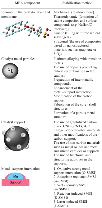
The degradation of the ionomer either as a membrane or as particles distributed in the electrode follows a few pathways that are often interrelated. The most significant among them are mechanical degradation, chemical degradation by radical attack, thermal degradation, colloidization, and ionomer migration in an electric field.
The described approaches to the formation of stable ionomers in MEA are reduced to mechanical stabilization by reinforcement (membrane reinforcement by related fluorinated polymers), kinetic stabilization using scavengers that reduce the radical concentration (filling with various species that provide free radical recombination, e.g., cerium ions), and structural stabilization (control of the morphology and porosity of the membrane to suppress the electrophoreic migration and use of nanostructured materials such as graphene or SiO2). An important trend is ionomer stabilization through the formation of surface compounds. Finally, the development of new stable membranes based on aromatic polymers is a persistent trend of ionomer stabilization.
It should be noted that the major part of studies addresses stabilization of particular membranes and almost neglects stabilization of the Nafion structure in the electrode.
The electrocatalyst of proton exchange membrane MEA includes three vulnerable components susceptible to attacks during the FC operation: metal particles, support, and metal/support interface. The metal particles can undergo several types of degradation: dissolution, agglomeration, and loss of contact with support.
Traditional supports are those based on carbon blacks with extensive surface area, mesopores, and relatively high electronic conductivity. However, the catalyst support experiences strong corrosive action, which leads to structure degradation, loss of contact with metal particles, shedding of particles, and poisoning of the catalyst metal.
Correspondingly, the measures against the catalyst degradation are directed towards prevention or mitigation of these degradation processes. A notable feature of the protective measures is the need to maintain the catalyst activity at a sufficiently high level.
Three main types of catalyst stabilization methods can be distinguished: thermodynamic, structural, and kinetic stabilization methods.
The thermodynamic stabilization is directed towards a decrease in the Gibbs energy of the system by means of a number of expedients: production of intermetallic compounds, alloys, core – shell structures, etc., and arrangement of certain (less harsh) operation conditions. As regards the catalyst support, a popular approach is based on the replacement of carbon with more oxidation-resistant materials. This method makes use of both thermodynamic stabilization, that is, the application of materials with a higher redox potential compared to that of carbon black (carbides, oxides, etc.) and kinetic stabilization, that is, graphitization of carbon black, resulting in retardation of oxidation reactions with some loss of the specific surface area.
Special mention should be made of the stabilization method based on the formation of surface compounds that thermodynamically stabilize the material: for example, the introduction of a nonmetal (P, N, etc.) into the platinum nanoparticle core; this stabilizes platinum through the formation of chemical bonds and inhibits the dissolution of platinum. A promising trend in the thermodynamic stabilization is the design and the use of strong metal–support interaction materials.
Structural stabilization implies the fabrication of structures that spatially restrict agglomeration of metal particles; this includes various types of encapsulation of metal particles, decoration of platinum nanoparticles with porous silica, and the design of spatially restricted structures (utilization of the structural factor by thorough control of Pt shell thickness in the core–shell structures at the atomic level). One trend in the structural stabilization that proved to be effective is the generation of electrode structures with spatially mismatched Pt/C and Nafion components by introducing multi-walled carbon nanotubes with a large aspect ratio into the electrode material and formation of the island structure of the Nafion polymer.
Analysis of the published data indicates that generation of the interfacial interaction between the functional materials of the membrane electrode assembly, resulting in the thermodynamic stabilization of the system, is a fairly promising way of stabilization of MEA components in electrochemical systems. Apart from the increase in the stability, in some cases, this expedient improves functional properties such as catalyst activity. The development of this trend may also be beneficial for the long-term durability of electrochemical systems.
6. List of abbreviations and symbols
Crossover — hydrogen or oxygen penetration through the membrane resulting in a decrease in the fuel cell efficiency.
Electrocatalyst — active element of the membrane electrode assembly (MEA), usually platinum nanoparticles, accelerating electrochemical reactions such as oxygen reduction and fuel oxidation reactions.
Electrochemical activity — the ability of the catalyst material to maintain the rate of reactions measured as the current per unit weight or area.
Fenton’s reagent — chemical test for evaluation of membrane and catalyst resistance to the action of free radicals.
Ionomer — polymer material providing the transport of ions (most often, protons) in the membranes or electrodes.
Proton exchange membrane — a membrane providing the proton conductivity and separating the anode and cathode compartments; a critically important part of a fuel cell.
A-SMSI — adsorbate-mediated strong metal–support interaction,
ADT — accelerated durability test,
AST — accelerated stress test, a method for accelerated testing of the durability of components for the simulation of long-term effects within short periods of time,
CTO — cerium titanium oxide,
CVC — current – voltage characteristics, the plot for current vs. the voltage, characterizing the operation of an electrochemical device,
CNFs — carbon nanofibres,
CNTs — carbon nanotubes,
CV — cyclic voltammetry, a type of voltammetry characterized by cyclic variation of the direction of polarization,
DOE — US Department of Energy,
EPR — electron paramagnetic resonance,
ECSA — electrochemically active surface area,
FC — fuel cell, a device for conversion of chemical energy of the fuel into electrical energy,
GO — graphene oxide,
L-SMSI — laser-induced strong metal – support interaction,
MA — mass activity, that is, mass catalytic activity,
MEA — membrane electrode assembly, the main part of the fuel cell in which the energy conversion takes place,
NWs — nanowires,
OCV — open circuit voltage, the voltage in the system without a current, the maximum electromotive force of the system,
O-SMSI — oxidative strong metal – support interaction,
ORR — oxygen reduction reaction, the key reaction taking place on the cathode in fuel cells, which determines the fuel cell efficiency,
PVDF — polyvinylidene fluoride,
PTFE — polytetrafluoroethylene,
PEMFC — proton exchange membrane fuel cell,
PFSA — perfluorosulfonic acid, an ionomer widely used in proton exchange membranes to provide high ionic conductivity and degradation resistance,
PEEK — polyether ether ketone,
PPSU — polyphenylsulfone,
rGO — reduced graphene oxide,
RDE — rotating disk electrode, a tool for stationary studies of redox reactions and measurement of the kinetic parameters,
R-SMSI — reaction-induced strong metal – support interaction,
SA — specific surface activity,
SEM — scanning electron microscopy,
SMSI — strong metal – support interaction,
TEM — transmission electron microscopy,
wcSMSI — wet chemistry strong metal – support interaction,
XPS — X-ray photoelectron spectroscopy.
References


![New polyimide ionomers derived from 4,4′-diamino-[1,1′-biphenyl]-2,2′-disulfonic acid for fuel cell applications](/storage/images/resized/ruydfaB80LDjlkYqsfOeUAZohOIODyq7bQzis5O7_small_thumb.webp)