Keywords
Abstract
Currently, transition to all-solid-state batteries from common lithium-ion batteries containing liquid electrolytes is relevant due to the risk of self-ignition and even explosion of the latter devices. Furthermore, for solid electrolytes, lithium metal, which has record high specific capacity compared to currently used carbon materials, can serve as the anode. This review analyzes for the first time the possibilities of transition to thin-film solid electrolytes in lithium power sources. The review addresses the set of problems related to material synthesis, technological principles of the formation of electrolyte samples of various thicknesses, and conductivity of electrolyte films that can be achieved. The set of data concerning the relationship between the electrolyte conductivity and film thickness is considered; the problem of specific conductivity decrease upon a decrease in the thickness of the electrolyte film is addressed. The implemented approaches to solving the problems of material degradation in the electrode–electrolyte interfacial region are systematized.
The bibliography includes 282 references.
1. Introduction
Lithium-ion batteries (LIBs) are widely used as electrochemical power sources in compact electronic devices and electric motors of vehicles and also in the electric power industry for energy storage and conversion systems and for coordinating the production and consumption of electricity during periods of peak loads. Lithium-ion batteries feature high performance characteristics such as increased specific capacity (280 Wh kg–1), high charge/discharge cycling stability, a wider range of operating temperatures (–20 to +60°C) compared to other types of batteries, low self-discharge (1.5% per month), and long storage period (5 years).[1-6] Currently, development of all-solid-state batteries (SSBs) is of interest throughout the world.[7-21] Switching from conventional lithium-ion batteries containing a liquid electrolyte (or polymer, or gel electrolyte) is necessary due to the risk of self-ignition or even explosion of such devices, especially when they are scaled-up. In addition, upon the transition to a solid electrolyte, it will be possible to use lithium metal as the anode material, which is relevant since lithium has a higher specific capacity (3860 mA h g–1) compared to currently used carbon materials (300 mA h g–1). The use of lithium metal may increase the battery performance to achieve a gravimetric energy density of more than 500 Wh kg–1, volumetric energy density of more than 1500 Wh L–1, safety, cyclability, and low cost.[22-25] Comparison of the energy characteristics of various types of batteries, including solid electrolyte batteries, is presented in Fig. 1a. The problem of fast charging of batteries is addressed in a number of reviews.[26-31] The use of fast charging in the case of conventional lithium-ion batteries decreases their service life due to overheating. From the theoretical standpoint, there is no need to regulate the charging rate in SSBs, since there is no electrolyte decomposition as in the case of liquid electrolytes; conversely, a temperature rise leads to improved ionic conductivity.
![[{"id":"QVfuw8K53T","type":"paragraph","data":{"text":"Characteristic ranges of volumetric and gravimetric energy density for solid-state batteries compared to other types of batteries (<i>a</i>);<sup>25</sup> number of publications on the topic ‘solid-state battery’ from 1990 to 2025 according to the Scopus database (<i>b</i>); tendency towards increasing volumetric and gravimetric energy density of solid electrolyte batteries with decreasing electrolyte thickness in the Li/NMC811, Li/S, and Li/LFP cells (<i>c</i>).<sup>24 </sup>SSEs are solid-state electrolytes; nmC is LiNi<sub>x</sub>Mn<sub>y</sub>Co<sub>z</sub>O<sub>2</sub>; LFP is LiFePO<sub>4</sub>; S is sulfur; SSBs are all-solid-state batteries; SSTFBs are all-solid-state thin-film batteries; Ni-MH are Ni metal hydride batteries. Figure 1<i>a</i> is published under the Creative Commons License. Figure 1<i>c</i> is reproduced from Ref. 24 [Energy Environ. Sci., 14, J.Wu, L.Yuan, W.Zhang, Z.Li, X.Xie, Y.Huang, Reducing the Thickness of Solid-State Electrolyte Membranes for High-Energy Lithium Batteries, p. 12, Copyright (2021)] with permission from the Royal Society of Chemistry."}}]](/storage/images/resized/LjH7dAFTq59xZVpBwTMWgbsULSZ5WkAJDjHLeAys_xl.webp)
According to the Scopus database, single papers including the term ‘solid-state battery’ (in the title, abstract, or keywords) appeared from 1990 to 2005. Since 2010, the number of publications in this area has been gradually increasing; this was especially pronounced in 2017. In 2024, the number of publications on this topic exceeded four thousand papers per year (Fig. 1b).
The possible benefits of the transition from bulk ceramic samples to film samples for the fabrication of all-solid-state power sources are the following:[24][25][32-38]
— faster diffusion of lithium ions;
— increase in the volumetric and gravimetric energy density (Fig. 1c);
— decrease in the cost of SSBs due to the lower consumption of expensive materials for the manufacture of solid electrolytes.
Numerous miniature electronic devices require autonomous micropower sources. All-solid-state thin-film microbatteries are considered to be perfect built-in power sources for microelectronic devices.[36] These batteries can be used in robotics and medicine.[25] In 2023, an all-solid-state battery was manufactured; however, the cost of this device is still higher than that of commercially available lithium-ion batteries and the capacity is low: 8 mAh per 1.4 g (energy density of 13.2 Wh kg–1), whereas lithium polymer batteries are characterized by higher capacity of 100 mAh and energy density of 250 Wh kg–1. Nevertheless, it is assumed that installing a solid-state battery in a sensor for robots will eliminate the need for regular battery replacement in the device.*
The prospects for industrial implementation of SSBs featuring thin-film solid electrolytes are determined by the following factors:
— the presence of basic manufacturing technologies worked out on a laboratory scale and using micro production units scalable for mass production;
— specific costs for the production/purchase of necessary materials and technological equipment, as well as energy consumption and environmental friendliness of the process.
The current state of studies in this area still corresponds to the first stage in which the cost-effectiveness cannot be assessed, that is, development of laboratory manufacturing technologies, including development of required materials are underway. However, the relationship between the energy efficiency of the device and electrolyte thickness has not yet been ultimately clarified, despite the apparently obvious efficiency of thin films, since there is no understanding of the optimal process design and there are no unified standards for the synthesis and certification of materials and devices. Diverse solid electrolytes manufactured as bulk materials (not less than 500 μm thick), promising for the use in all-solid-state batteries, are addressed in numerous reviews.[39-58] These reviews mainly focus on lithium-conducting electrolytes of various structures, indicating their target characteristics, lithium-ion conductivity and density of ceramic membranes, details of synthesis and doping to improve the performance, and also their drawbacks and limitations for the fabrication of all-solid-state SSB samples. However, it should be borne in mind that decrease in the thickness of solid electrolyte films would inevitably decrease their mechanical strength and increase the risk of film degradation or lithium dendrite penetration, which in turn may result in internal short circuits. Here, we present for the first time an integrated analysis of characteristics of various classes of solid electrolytes to switch from bulk samples to thin-film analogues. In other words, in this review, we consider the set of characteristics of electrolytes (conductivity, mechanical properties) and electrolyte thickness in the context of processes for the synthesis of materials and fabrication of electrolyte membranes.
* Unfortunately, this information is available only from news sources. https://biz.maxell.com/en/rechargeable_batteries/assb-specceramicpackage.html.
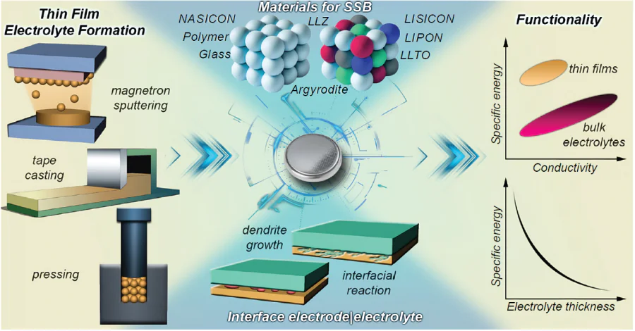
2. Materials for SSBs and methods for the fabrication of thin-film samples
Solid electrolyte membranes can be conventionally subdivided in terms of thickness into thin-film and bulk ones: solid electrolyte cells with thickness of up to a few hundred micrometres are classified as film electrolytes to be distinguished from the most frequently encountered cells with electrolyte thickness of ~ 500 μm. It is of interest to elucidate the general patterns of the variation of electrolyte properties depending on the thickness under particular formation conditions and applied technologies.
2.1. Conductivity of bulk samples
The most promising materials of solid electrolytes include argyrodite, garnet, and perovskite type oxide compounds, NASICON, LISICON, and LiPON, and S-containing materials, sulfides. Lithium-conducting polymer materials and glasses are being actively studied.
The NASICON electrolytes have a rhombohedral structure corresponding to space group R-3c. The most prominent representatives of this class of compounds are Li1 + xAlxTi2 – x(PO4)3 (LATP) and Li1 + xAlxGe2–x(PO4)3 (LAGP), characterized by high lithium-ion conductivity (~ 10–4 S cm–1 at room temperature) of bulk samples with a thickness of 0.5 – 1.0 mm. A specific feature of the production of LAGP-based electrolyte membranes is that melting glass of this composition followed by crystallization gives high-density and highly conductive solid electrolyte. A drawback of LATP-based solid electrolytes is the lack of compatibility with many low-potential anode materials, including lithium, due to the presence of Ti4+, which is readily reduced in contact with low-potential anodes. Solid electrolytes based on LAGP are stable in contact with most electrode materials, including Li anode at room temperature. However, they are synthesized using expensive germanium oxide (GeO2) as a starting reactant, which complicates the use of LAGP-based materials in industry. A large number of studies have been devoted to this class of solid electrolytes, but the main focus of the studies is on bulk samples. A series of studies on optimization of the production process of NASICON type bulk solid electrolytes with a dense microstructure and high overall conductivity was conducted by Russian scientists: S.V.Pershina,[59-61] I.A.Stenina,[62][63] and G.B.Kunshina.[64-66]
It is noteworthy that glassy solid electrolytes can be used to produce monolithic membranes without grain boundary resistance. Casting of a glass melt makes it possible to produce samples with a thickness of more than 100 μm. Oxide-based glasses have low conductivity at room temperature (~ 10–6 S cm–1); the conductivity of sulfide-based glasses is several orders of magnitude higher (~ 10–3 S cm–1);[67] however, the latter are unstable in air due to high reactivity towards water vapour.[48] The most promising line of research is selection of conditions for the crystallization of oxide-based glasses to give crystalline solid electrolytes with high conductivity. This method proved to be promising in relation to LAGP, as it enabled the production of ceramics with a density of 100% relative to the theoretical value.[68] This, in turn, made it possible to form solid LAGP electrolytes as thin slices from a previously obtained bulk material (Fig. 2). Thus 200 μm-thick samples of LAGP electrolyte were produced by diamond wire slicing of glass-ceramic bulk LAGP samples, which were manufactured by hot pressing of glass powder followed by crystallization (sample 1).[69] Another thin-film sample with a thickness of ~ 290 µm was obtained by cutting the bulk material immediately after hot pressing, with crystallization being carried out in the thin sample (sample 2); the resulting room-temperature (rt) conductivity was 1.2 × 10⁻⁴ S cm–1. The sequence of operations affected the microstructure of the samples: the sample with higher density and higher conductivity (3.3 × 10⁻⁴ S cm–1) was formed when cutting was performed after crystallization and completion of microstructure formation in the bulk material (sample 1). Thus, the authors confirmed the possibility of preparing LAGP electrolyte as thin slices with a total conductivity of 3.3 × 10⁻⁴ S cm–1, characteristic of bulk electrolyte materials. The relative density of thin plates of LAGP electrolytes was 98.9% and 88.7% for samples 1 and 2, respectively. It is noteworthy that the wire cutting speed was low, amounting to 0.1 mm min–1, which, in our opinion, restricts the productivity of this technology. Nevertheless, the above example demonstrates more favourable conditions for achieving high ionic conductivity by means of the initial formation of the slice microstructure within the bulk sample.
![[{"id":"2VJlCYLQfO","type":"paragraph","data":{"text":"Schematic diagram of the hot pressing method (<i>a</i>). Cross-sectional SEM images of samples <b>1</b> (<i>b</i>) and <b>2</b> (<i>c</i>) of LAGP electrolyte.<sup>69</sup> Figures 2<i>b</i> and 2<i>c</i> are reproduced from Ref. 69 [RSC Adv., 9, M.Kotobuki, H.Lei, Y.Chen, S.Song, C.Xu, N.Hu, L.Lu. Preparation of thin solid electrolyte by hot pressing and diamond wire slicing, p. 11670, Copyright (2019)] with permission from the Royal Society of Chemistry."}}]](/storage/images/resized/skjSomj2UV6jxWINoJgLY292dz46uXQ7fpD6imoc_xl.webp)
Among polycrystalline solid electrolytes, there are compounds with a cubic lattice structure and space group Ia-3d. The most prominent representative of this class is Li7La3Zr2O12 (LLZ), which was obtained by Murugan et al.[70] and exhibited high lithium-ion conductivity (3 × 10⁻⁴ S cm–1 at 25°C) and stability in contact with lithium. Currently, using doping of the compound and optimization of the synthesis method, researchers were able to increase the lithium-ion conductivity for bulk LLZ samples synthesized by solid-phase (SP) and sol–gel (SG) methods by an order of magnitude, up to ~ 10–3 S cm–1.[71-73] A drawback of solid electrolytes based on LLZ is the lack of stability in air in the presence of H2O and CO2, which results in the formation of lithium carbonates. It was noted that a higher relative density of the sintered LLZ electrolyte corresponds to higher Li-ion conductivity [9.4 × 10⁻⁶ S cm–1 (85%) and 3.4 × 10⁻⁴ S cm–1 (98%)] of the electrolyte material.[74] In particular, it was shown that hot pressing at a temperature of 1050°C for 30, 60, 90, and 240 minutes provides a relative density of sintered bulk ceramics of 85%, 95%, 96%, and 98%, respectively. An increase in the relative density from 85% to 98% corresponded to an increase in the average grain size from 2.7 to 3.7 μm and increase in the conductivity from 9.4 × 10⁻⁶ to 3.4 × 10⁻⁴ S cm–1.
The use of materials with the perovskite structure, Li3xLa2/3 – xTiO3 (LLTO), as solid electrolytes has been reported. These electrolytes are characterized by moderate lithium-ion conductivity (~ 10–5 S cm–1) and low electrochemical stability because of the presence of titanium ions. The bulk samples of perovskite-type solid electrolytes, Li3/8Sr7/16Ta3/4Zr1/4O3 and Li3/8Sr7/16Ta3/4Hf1/4O3, synthesized by SP method had a higher conductivity (~ 10–4 S cm–1).[45] A drawback of these electrolytes is high sintering temperature (1200 – 1300°C).
The LISICON solid electrolytes have a γ-Li3PO4-like crystal structure. The oxide representatives of this class of solid electrolytes have low total lithium-ion conductivity at room temperature, particularly, ~ 10–6 S cm–1 and ~ 10–5 S cm–1 for bulk samples of Li14Zn(GeO4)4 and Li3 + xGexV1 – xO4, repectively,[42][47] The replacement of O2– with S2– (Li10GeP2S12) provided a considerable increase in the lithium-ion conductivity up to ~ 10–4 S cm–1.[42][47][49] The most well-known representatives of thio-LISICON structures, Li4 – xGe1 – xPxS4 and Li10GeP2S12, prepared by mechanically activated SP synthesis, have high conductivity of 10–2 – 10–3 S cm–1 (bulk samples). Drawbacks of these solid electrolytes include the lack of stability towards water vapour, resulting in the formation of H2S. The electrolyte synthesis and processing must be carried out in a dry space or in an argon atmosphere, which markedly complicates both systematic research of the process and technology scaling to an industrial level.
Argyrodite-type lithium-conducting electrolytes Li6PS5X (X = Cl, Br, I) are characterized by high Li-ion conductivity, in particular, a room-temperature conductivity of ~ 10–3 S cm–1 was attained for 100 μm-thick ceramic membranes. A disadvantage of these electrolytes, as in the case of sulfide materials, is the instability in air.[52]
The lithium-ion conductivity values achieved for bulk samples of various classes of solid electrolytes are summarized in Table 1.

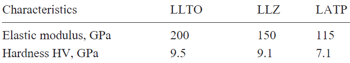
The mechanical properties of the electrolyte should be highlighted as an important factor determining the functional characteristics of SSBs. Papakyriakou et al.[75] investigated the mechanical properties of solid electrolytes based on inorganic sulfides (LSPS, LPSCl) and oxides (LAGP, LLZTO). The mechanical properties of Li-conducting solid electrolytes are important for battery performance, long-term stability, and safety. It was noted[76] that to prevent the growth of dendrites at the solid electrolyte|Li anode interface, the shear modulus of the electrolyte material should be at least two times higher than the shear modulus of the Li anode. The LLZ electrolyte material is characterized by a shear modulus in the range of 56 – 61 GPa, whereas the shear modulus of lithium metal is ~ 4 – 5 GPa.[77] Nevertheless, despite the high shear modulus of LLZ, which is favourable for suppressing the dendrite growth, dendrite growth still does take place at the electrolyte|Li-anode interface when the current density is above 0.5 mA cm–2. It was shown[78] that fracture toughness of the electrolyte influences the critical maximum charging current of a battery. The fracture toughness characterizes the resistance of a material to destruction caused by crack propagation. The LLZ electrolyte material has a Poisson’s ratio ν ~ 0.26.[79]
The elastic modulus and hardness values for the main classes of oxide solid electrolyte materials (LLTO, LLZ, LATP) are summarized in Table 2.[80] Hardness of an electrolyte characterizes the material resistance to irreversible surface deformation upon indentation. The LLTO, LLZ, and LATP materials have low fracture toughness Kc ~ 1 MPa√m and are brittle.
It was noted that an increase in the relative density of sintered LLZ electrolytes leads to increasing Vickers hardness [4.7 ± 0.2 GPa (85%) and 9.3 ± 0.5 GPa (98%)], apart from increasing lithium-ion conductivity of the electrolyte material.[74] It is worth noting that an inverse dependence was obtained for the electrolyte fracture toughness, namely, an increase in the relative density and an increase in the ceramic grain size lead to decreasing fracture toughness [2.37 MPa√m (85%) and 0.97 MPa√m (98%)]. Presumably, higher fracture toughness found for lower-density samples is due to the increased intergranular porosity at grain boundaries, which weakens the grain boundaries and induces deflection of cracks out of the plane of maximum driving force.
2.2. Conductivity of thin-film samples
2.2.1. Conductivity of thin-film polymer electrolytes
Lithium-conducting polymer electrolytes are inert polymer matrices such as polyethylene oxide (PEO), polyvinylidene fluoride (PVDF), and so on, containing a dissolved lithium salt [lithium bis(fluorosulfonyl)imide (LiTFSI), hexafluorophosphate (LiPF6), or perchlorate (LiClO4)]. Thin films of solid electrolytes are cast from solutions using polymer electrolytes. However, this approach is faced with complications associated with the limited range of electrochemical stability of the material in which it is neither oxidized nor reduced and low thermodynamic stability of the electrolyte in contact with lithium metal, which brings about the problem of safe operation of these devices, as in the case of conventional lithium-ion batteries. Thin films of polymer electrolytes are characterized by low total ionic conductivity at room temperature. As a solution to this problem, transition to composite electrolytes comprising a polymer matrix with a ceramic filler or liquid electrolyte is considered.[56][81-86]
Yaroslavtsev and co-workers[56] analyzed the prospects for the fabrication of composite electrolytes with inert and active fillers. The inert fillers include non-conductive compounds such as Al2O3, SiO2, ZrO2, etc. Lithium-conducting inorganic solid electrolytes are used as active fillers. The authors concluded that electrolytes of choice are composites with active fillers that possess their own Li-ion conductivity and form percolation networks. Thus, composite electrolytes containing active filler particles such as LAGP, LLZ, LATP, LTO, Li6PS5Cl, and Li10GeP2S12 provide the formation of thin films with lithium-ion conductivity ranging from 10–4 to 10–3 S cm–1 at room temperature. For example, the use of polypropylene oxide (PPO) made it possible to fabricate a solid electrolyte film of LAGP/PPO composite with higher conductivity: 3.5 × 10⁻⁴ S cm–1 at 25°C.[87] Upon the addition of PEO with LiTFSI, a 90 μm-thick LAGP film had a conductivity of 7.6 × 10⁻⁴ S cm–1 at room temperature.[88]
Sulfide-based inorganic solid electrolytes are flexible and can be rolled to form thin membranes with a thickness of 15 to 20 μm by adding a small amount (~ 0.5 wt.%) of the polytetrafluoroethylene (PTFE) as a polymer binder.[89-91] This technique makes it possible to eliminate the use of solvent required in the tape casting method and heat treatment of the electrolyte and to avoid the formation of pores during the burnout of organic components. In a study by Jiang et al.,[92] the Li10GeP2S12 solid electrolyte powder was mixed with the PTFE binder and then a 100 μm film with a conductivity of 3.6 × 10⁻⁴ S cm–1 was fabricated by rolling. Liu et al.[93] mixed particles of the Li6PS5Cl solid electrolyte with the PTFE binder, and the subsequent rolling followed by drying afforded a 100 μm film with a conductivity of 5.09 × 10⁻³ S cm–1. Tron et al.[94] studied the effect of various binders on the formation of electrolyte film (with a thickness of 90 – 120 μm) based on Li6PS5Cl. The room-temperature conductivity of the obtained composite electrolytes varied from 5.8 × 10⁻⁴ (butadiene nitrile rubber) to 1.3 × 10⁻³ S cm−1 (polyisobutylene), depending on the introduced polymer. The authors noted that obtaining films with a thickness less than 100 μm required additional grinding of Li6PS5Cl particles; however, this mechanical treatment resulted in a decrease in the specific conductivity of the solid electrolyte. For further optimization of the formation of sulfide-based films, in particular, to achieve both mechanical strength and high conductivity, it was proposed to introduce a combination of two or more binders.
2.2.2. Conductivity of thin-film oxide (ceramic) electrolytes
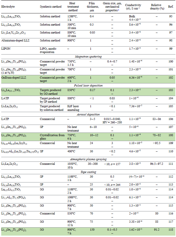
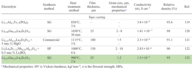
The methods used to form thin-film solid electrolytes can be conventionally subdivided (Table 3)[95-113][114-123] into methods based on the use of precursors [chemical vapour deposition and solution precipitation (solution method)] and those using powders of a pre-synthesized compound (tape casting, electrophoretic deposition, atomic layer deposition; magnetron sputtering; and pulsed laser deposition).
2.2.2.1. Methods based on the use of precursors
Solid electrolyte membranes are obtained using various processes, including chemical vapour deposition in the case of thin films with a thickness ranging from a few tens of nanometres to a few micrometres; and anodic evaporation and solution methods for up to a few micrometres thick films (Fig. 3).[79][124][125]
![[{"id":"N6eoY8Xcy6","type":"paragraph","data":{"text":"Schematic diagrams of the methods: chemical vapour deposition (<i>a</i>), anodic evaporation (<i>b</i>), solution method (<i>c</i>)"}}]](/storage/images/resized/gSKiOHaPxyF6ML9nSjgUOOJjm3ptUYNTBHRkgAKI_xl.webp)
The group of methods involving vapour deposition can be used to fabricate submicron ultra-thin films. For example, the review by Su et al.[125] describes the use of atomic and molecular layer deposition methods for the formation of thin-film solid electrolytes on a substrate surface in contact with a gas vapour phase containing precursors of the coating (Fig. 3а). For the fabrication of highly conductive ceramic membranes, an important factor is selection of precursors and deposition conditions. The room temperature conductivity of various classes of lithium-conducting solid electrolytes varies from 10–9 to 10–7 S cm–1.
Quite a few studies address thin films of LiPON (lithium phosphorus oxynitride) electrolytes, which usually have low lithium-ion conductivity (~ 10−6 S cm–1). However, these solid electrolytes are promising for the fabrication of SSBs with thin-film electrolytes, since LiPON films can be prepared via sputtering methods in which some oxygen atoms in Li3PO4 are replaced with nitrogen atoms.[126-129] Thin films of LiPON (Li3 – yPO4 – xN1 – x – y) with a thickness ranging from a few tens of nm to 1 – 2 μm obtained by magnetron sputtering,[130][131] atomic layer deposition,[132] and pulsed laser deposition[133] have amorphous structure and a conductivity of 10–5 – 10–6 S cm–1. A method for anodic evaporation of LiPO3 in Ar/N2 plasma (Fig. 2b) and vapour deposition onto metal substrates has been proposed; this gave thin (1 μm-thick) films of amorphous solid electrolyte with an ionic conductivity of 1.7 × 10⁻⁵ S cm–1 at room temperature.[99] The method is based on heating of a crucible with electrons accelerated in the anode potential drop layer, which is accompanied by melting and evaporation of the base compound (e.g., LiPO3) followed by interaction of the vapour with the discharge plasma. Kamenetskikh et al.[134] used anodic evaporation of Li3PO4 in a low-pressure arc to obtain LiPON (1 μm-thick) films with an ionic conductivity of ~ 2 × 10⁻⁶ S cm–1. Madinabeitia et al.[129] showed good prospects for the design of monolithic all-solid-state lithium batteries on a stainless-steel substrate. Using magnetron sputtering, the authors deposited the LiNi0.5Mn1.5O4 cathode material and then LiPON solid electrolyte (2.0 × 10⁻⁶ S cm–1 at room temperature), and this was followed by Li anode deposition by thermal evaporation; the thickness of the assembled cell was less than 5 μm. The specific capacity of the manufactured cell was more than 70 mAh g−1 after 25 cycles.
Solution methods are used to fabricate films with a thickness of up to 1 μm (Fig. 3c). Bitzer et al.[97] utilized a solution method to obtain a 50 nm-thick film of LLZ-based solid electrolyte. After heat treatment at 800°C, the conductivity of the thin-film electrolyte amounted to 3.4 × 10⁻⁸ S cm–1. Low conductivity values were attributed to the formation of impurity phases. Using a solution method, Tadanaga et al.[98] prepared Al-doped LLZ films with a thickness of 1 μm on a MgO substrate. In order to improve the film morphology and obtain a dense, defect-free coating, an ionic surfactant, lithium dodecyl sulfate, was added to the solution. The room-temperature conductivity of the thin-film electrolyte after annealing at 900°C was 2.4 × 10⁻⁶ S cm–1.
The mechanism of film formation from a solution[124] considerably differs from vapour deposition and does not require the use of high-precision, expensive equipment. However, solution methods suffer from drawbacks such as complicated synthesis of precursors and long duration of the process, which implies multiple cycles of substrate dipping into the precursor solution. In addition, the need to use solvents in amounts 5 – 20 times greater than the weight of the powder gives rise to a large amount of waste.
2.2.2.2. Methods based on the use of powders of pre-synthesized compounds
Sputtering methods are applicable for the manufacture of films with a thickness of about 1 μm. These methods are based on evaporation of a target made of a solid electrolyte (Fig. 4a). In the case of lithium-containing compounds, it is necessary to use non-stoichiometric compositions in order to compensate for lithium losses during film formation associated with mechanisms of Li heating and evaporation, including scattering of light lithium particles on O2, N2, and Ar molecules in the gas phase during the deposition.[135] A lithium deficiency in the deposited film may cause a conductivity gradient of two orders of magnitude.[136] In particular, Li2O evaporation during sintering at temperatures above 1000°C is a considerable problem for LLZ-based solid electrolytes. Therefore, to reduce the vaporization intensity, the electrolyte material is sintered under a pile of the same powder (LLZ), and up to 15 wt.% excess of Li is used in the precursor. The problem of lithium oxide vaporization during annealing of electrolyte membranes is critical for ensuring the stoichiometric and phase composition of the electrolyte, which is particularly relevant for film samples. On going to thin-film designs and using various deposition methods, many researchers are faced with the problem of lower conductivity of the resulting films compared to bulk analogues. The review by Singh et al.[137] addresses the influence of the methods of synthesis of the powder and manufacture of the target used in various sputtering methods on the conductivity and density of the resulting LLZ thin films. The developed methods can be used to obtain films with a thickness of less than 1 μm, but their conductivity is several orders of magnitude lower than that of bulk analogues. Only Zhu et al.[102] were able to manufacture a highly conductive solid electrolyte film (6.36 × 10⁻⁴ S cm–1 at 25°C) by radio-frequency magnetron sputtering of numerous LLZ/Li2CO3/Ga2O3 nanolayers followed by annealing at a temperature of 600°C for 2 h. Ran and Tiwari[105] prepared 1 μm-thick solid electrolyte (LLZ) films by pulsed laser deposition (PLD) on SrTiO3 substrates. Immediately after deposition, the LLZ films were amorphous and had a conductivity of 3.35 × 10⁻⁷ S cm−1 at 25°C. The film material was crystallized by laser annealing, which somewhat increased the Li-ion conductivity to 7.36 × 10⁻⁷ S cm–1 at 25°C.
![[{"id":"6KTMXRxp_2","type":"paragraph","data":{"text":"Schematic diagram of coating deposition by target sputtering (<i>a</i>); SEM image of deposited LAGP film after annealing at 700°C (<i>b</i>) and 750°C (<i>c</i>) and element distribution maps in the coating.<sup>100</sup> Figure 4<i>b</i> and 4<i>c</i> are reproduced from Ref. 100 [Solid State Ionics, 354, T.Mousavi, X.Chen, C.Doerrer, B. Jagger, S.C. Speller, C.R.M.Grovenor. Fabrication of Li<sub>1</sub><sub> + x</sub>Al<sub>x</sub>Ge<sub>2</sub> <sub>– x</sub>(PO<sub>4</sub>)<sub>3</sub> thin films by sputtering for solid electrolytes, p. 115397; Copyright (2020)] with permission from Elsevier."}}]](/storage/images/resized/CbfuzSW2o5so69fNZkOneB8bG4Ly7CnlzOV4ct23_xl.webp)
The magnetron sputtering method was used to obtain LAGP solid electrolyte films with a thickness of 0.95 – 1.3 μm on an Al2O3 substrate.[100] In order to achieve this electrolyte thickness, it was necessary to carry out the film sputtering process for a fairly long period of time (6 h). To form the microstructure of the coatings, the obtained film was annealed at 450 – 750°C (1.5 h), which required additional annealing in a pile of LAGP powder to reduce lithium oxide vaporization. The optimization of heat treatment and sputtering conditions made it possible to achieve a conductivity of the LAGP electrolyte film of 1.48 × 10⁻⁴ S cm–1 at 20°C. When the annealing temperature was 700°С, a dense film powder was obtained (Fig. 4b), while raising the annealing temperature to 750°С resulted in generation of pores through the film (Fig. 4c), which was attributed to vaporization of volatile components (lithium oxide).
The methods based on the use of pre-synthesized powders include aerosol deposition (Fig. 5a), atmospheric plasma spraying (Fig. 5b), tape casting (Fig. 5c), and electrophoretic deposition (Fig. 5d).
![[{"id":"JGw4VEVCy6","type":"paragraph","data":{"text":" Schematic diagrams of aerosol deposition (<i>a</i>), atmospheric plasma spraying (<i>b</i>), tape casting (<i>c</i>), and electrophoretic deposition (<i>d</i>)"}}]](/storage/images/resized/ZZXE2wP4VAEAGjdr1KJb7uOFR4ydVbTDLQeKHm1n_xl.webp)
Aerosol deposition methods make it possible to prepare films with a thickness of 10 – 30 μm on various substrates at room temperature at a higher speed (120 μm min–1) compared to vacuum deposition methods. (1 – 20 μm h–1). In this case, a powder material is deposited onto the substrate as a result of acceleration of solid particles in a carrier gas flow, giving rise to a coating with good adhesion to the substrate without the use of heat treatment processes (Fig. 5a). Aerosol deposition is accompanied by impact consolidation of the material, which is due to the high velocity of particles that are accelerated in the nozzle by a gas flow and to the impact interaction of the particles with the substrate and pre-deposited layer, thus providing compaction of the coating. This may give various oxide solid electrolytes with a room temperature conductivity of 10–7 to 10–5 S cm–1.[138] For example, annealing of an approximately 30 μm-thick Li6.025Al0.2La3Zr1.625Ta0.375O12 film at 400°C induces a conductivity increase from 1.6 × 10⁻⁸ to 4.6 × 10⁻⁵ S cm–1. While previous studies were mainly focused on the influence of factors such as impact velocity, the distance between the nozzle and the substrate, and gas pressure, Han et al.[139] found out that the morphology and size distribution of the sprayed particles are key factors in the aerosol deposition of LLZ membranes for the stable growth of a dense, highly conductive solid electrolyte membrane. In the case of small particles (0.4 μm), their insufficient kinetic energy prevented the film formation, whereas the use of larger particles (> 10 μm) resulted in film erosion and restricted film growth. The use of medium-size particles (~ 3 μm) furnished a 24 μm-thick film requiring no heat treatment with conductivity of 1.18 × 10⁻⁵ S cm–1.
The aerosol deposition can be used to obtain LAGP ceramic membranes with a thickness of about 10 μm, the porosity of which depends not only on the heat treatment temperature, but also on the size of the initial LAGP particles.[107] Dense LAGP films with a conductivity of 5 × 10⁻⁶ S cm–1 were fabricated using LAGP powders with an average particle size of 0.5 – 1 μm. The conductivity was much lower (by two orders of magnitude) than that of bulk LAGP samples, which is mainly due to great grain boundary resistance between fragmented LAGP particles in the film.
Films of LLZ solid electrolyte with a thickness of 30 to 300 μm were formed by atmospheric plasma spraying (Fig. 5b).[111] A commercial solid electrolyte powder with an average particle size of 58.3 μm was used as the sprayed material. The conductivity of LLZ films at room temperature after the heat treatment at 1050°С for 10 h was 3.82 × 10⁻⁴ S cm–1. The mechanical properties of the thin-film electrolyte were measured: the flexural strength of the solid electrolyte with a thickness of 300 μm was 157 MPa.
Tape casting can be considered to be the most promising method for forming layers of lithium-ion solid electrolytes; this method does not require expensive unique equipment and can be adapted to industrial production conditions. The method consists (Fig. 5c) in the preparation of a slurry by mixing a solid electrolyte powder with organic additives (polyvinyl butyral, benzyl butyl phthalate, etc.), which are introduced as solutions in organic solvents (ethanol, acetone, toluene, etc.). The tape casting technology involves the choice of organic components (binder, plasticizer, and dispersing agent) to form uniform continuous coatings, including the stage of burnout of the organic binder during annealing and sintering of the layers.[79] The addition of organic components is necessary to form a consolidated tape of a specified shape during casting, prevent particle agglomeration, and prevent tape cracking. A benefit of tape casting method is that the resulting tape is flexible after drying. (Fig. 6а).
![[{"id":"gbqxWpml__","type":"paragraph","data":{"text":"Examples of using tape casting for the formation of LLZ based electrolyte: (<i>a</i>) prepared Al-LLZ flexible type electrolyte (350 μm thick);<sup>121</sup> (<i>b</i>) SEM image of a fracture section of Al-LLZ electrolyte containing MgO (5 wt.%) obtained by tape casting followed by sintering at 1115°C for 3 h (Ref. 121); (<i>c</i>) Li<sup>+</sup> transfer in LLZ with Li(G<sub>4</sub>)FSI ionic liquid. Figure 6<i>a</i> and 6<i>b</i> are reproduced from Ref. 121 [Energy Fuels, 35, R.A.Jonson, E.Yi, F.Shen, M.C.Tucker, Optimization of tape casting for fabrication of Li<sub>6.25</sub>Al<sub>0.25</sub>La<sub>3</sub>Zr<sub>2</sub>O<sub>12</sub> sheets, p. 8982; Copyright (2021)] with permission from American Chemical Society."}}]](/storage/images/resized/eME1HyKYl28oTlxGtUxFKmWUHTI2YD7Ga76yaepF_xl.webp)
As a drawback of this method, note the difficulty of achieving high density (more than 90%) for ceramic membranes after burnout of organic components and sintering of the film.[79][139][140] A way to solve this problem is to use sintering additives (e.g., Li3BO3, MgO, etc.) and fabrication of composite electrolytes (Fig. 6b). For example, the introduction of 5 wt.% MgO into Li6.25Al0.25La3Zr2O12 increased the relative density to 91.1% and provided a conductivity of 2.3 × 10⁻⁴ S cm–1.[121] Jonson and McGinn[122] used Li3BO3 as a sintering additive to Li7La3Zr1.75Nb0.25Al0.1O12; the resulting composite films had a conductivity of 2.83 × 10⁻⁴ S cm–1 at ~ 150 μm thickness and relative density of 90%. Using tape casting, Cheng et al.[84] fabricated a film (Fig. 6с) of Al-doped LLZ (Al-LLZ), which was additionally pressed at a pressure of 700 MPa; the film porosity was 15%. The authors filled the pores with an ionic liquid, Li(G4)FSI [tetraethylene glycol dimethyl ether (tetraglyme or G4) fluorosulfonyl imide (FSI)]. The conductivity of the ~ 230 μm thick film reached 1.1 × 10⁻⁴ S cm–1.
Paolella et al.[116] mixed a powder of the LAGP solid electrolyte with polyvinyl difluoride-hexafluoropropylene in a mixture of DMF and THF and tape-cast a 70 – 100 μm-thick film. The organic components were removed by annealing the electrolyte film at a temperature of 850°C; the film conductivity was 2 × 10⁻⁵ S cm–1 at 25°C and the relative density was 80%. A 75 μm-thick LAGP film was obtained by tape casting. After the subsequent hot pressing and sintering in air at 900°С for 12 h, the film conductivity was 3.38 × 10⁻⁴ S cm–1 (25°C).[117] The achieved density of the electrolyte depended on the sintering temperature: when the sintering temperature was 900°С, the relative density reached 83, 88, and 87% for sintering time of 8, 12, and 15 h, respectively.
Yi et al.[123] proposed an additional mechanism for densification of the powdered Li6.25Ga0.25La3Zr2O12 electrolyte during sintering of the film obtained by tape casting. The authors used nanoparticles produced by flame spray pyrolysis of an electrolyte precursor solution. This technique for the fabrication of nanopowders resulted in the formation of high surface and reaction energy of particles, which promoted film sintering without application of elevated pressure. The process gave thin films of Ga-doped LLZ (25 μm) with a relative density of 95 ± 1% and a grain size of 1.2 ± 0.2 μm; the room-temperature conductivity was 1.3 × 10⁻³ S cm–1.
It is worth noting that the tape casting allows for the targeted design of porous structures.[85][141] For example, Bao et al.[85]designed a ceramic skeleton, Li6.5La3Zr1.5Ta0.5O12, with a thickness of 12 μm, which was then filled with a polymer electrolyte. The resulting composite electrolyte had a high conductivity of 1.19 × 10⁻³ S cm–1.
Electrophoretic deposition (EPD) is known as a production technology of thin-film coatings, in particular, it was used to form a solid electrolyte layer for solid oxide fuel cells (SOFC).[142-145] The EPD technology is based on the electrophoresis effect, which implies that particles suspended in a liquid medium move under the action of an electric field applied to electrodes (see Fig. 5d ). The physicochemical properties of the suspensions give rise to an excess charge on the particles and induce the formation of an electric double layer (EDL) on the electrodes. In the electrode region, this gives a coagulated deposit and a coating.[146][147] The final formation of the solid electrolyte layer occurs via high-temperature sintering. Despite the extensive use of EPD for the fabrication of SOFCs, the use of this method in the SSB technology is less known and mainly applies to the formation of electrode layers.[148] Il’ina, Kalinina, and co-workers[149][150] demonstrated the possibility of forming LLZ thin films by the EPD method and analyzed the problem of decreasing conductivity of thin films compared to that of bulk solid electrolytes. Mention should be made of the following important factors that determine the properties of the LLZ layer, namely, the effects of the substrate material and composition of the gas atmosphere during the annealing of the coating. For example, it was found that fibrous Li2CO3 phase is formed in air upon the reaction of the electrolyte with atmospheric CO2 to give Li2CO3; however, some amount of this phase is also formed even in the argon atmosphere since argon contains trace amounts of CO2. The metal substrate has no direct influence on the formation of the LLZ electrolyte layer; however, Ti substrate promotes adsorption of CO2 during annealing, which makes it possible to avoid the undesirable formation of lithium carbonate, whereas upon annealing of an LLZ layer in argon on a Ni substrate or on a stainless steel, the formation of the Li2CO3 does occur.
Currently, as a result of studies of lithium-conducting solid electrolytes, high conductivity values (~ 10–3 S cm–1 at room temperature) have been achieved in 1 μm-thick films for most classes of compounds (Fig. 7). It is noteworthy that the conductivity of solid electrolytes is strongly affected by the technology used to fabricate the thin film. However, no data on the mechanical properties of thin-film solid electrolytes are available from the literature (see Table 3); meanwhile, along with the lithium-ion conductivity, mechanical characteristics of a solid electrolyte are important for the transition from bulk to thin-film samples. This emphasizes the need to standardize the methods for certification of thin-film electrolytes, which will enable comparison of the electrolytes and selection of the optimal production methods.
![[{"id":"6Do0BaB8jd","type":"paragraph","data":{"text":"Main classes of Li-conducting solid electrolytes; characteristic conductivity ranges at 25°С, and electrolyte thicknesses. The following designations are used: LISICON (lithium superionic conductor) is Li<sub>14</sub>Zn(GeO<sub>4</sub>)<sub>4</sub> and Li<sub>3 + x</sub>Ge<sub>x</sub>V<sub>1 – x</sub>O<sub>4</sub>; thio-LISICON is Li<sub>4 – x</sub>Ge<sub>1 – x</sub>P<sub>x</sub>S<sub>4</sub> and Li<sub>10</sub>GeP<sub>2</sub>S<sub>12</sub>; NASICON (sodium superionic conductor) is Li1 + xAlxTi2 – x(PO4)3 (LATP) and Li1 + xAlxGe2 – x(PO4)3 (LAGP); LLTO is Li<sub>3x</sub>La<sub>2/3 – x</sub>TiO<sub>3</sub>; LLZ is Li<sub>7</sub>La<sub>3</sub>Zr<sub>2</sub>O<sub>12</sub>; LIPON is lithium phosphorus oxynitride; argyrodite is Li<sub>6</sub>PS<sub>5</sub>X (X = Cl, Br, I)."}}]](/storage/images/resized/tgMNATTOBriwv722XL0MYzImiRhOXjARu1Y7Sz4t_xl.webp)
It is necessary to emphasize the importance of grain boundaries, which have an adverse effect on the electrolyte conductivity, namely, the grain boundaries hinder ion transport, thus increasing ohmic loss. The blocking effect of grain boundaries arises[151][152] due to disorders of microstructure at the grain boundaries, formation of a positive volume charge in these areas, and the depletion of Li+ ions in these areas. The decrease in the ionic conductivity of grain boundaries compared to the bulk conductivity may reach a few orders of magnitude. In solid electrolytes, the effect of positive volume charge can be more pronounced than in liquid electrolytes.[153] The ion transport may be hindered due to the distortion of the grain structure near the boundaries. This was found[154] by the atomic-level simulation (molecular dynamics) in relation to the sharp decrease in the Li-ion conductivity of the solid model electrolyte Li3OCl upon decrease in the grain size below 100 nm. Meanwhile, as the grain size increases to 500 nm, the conductivity reaches only 85% of the initial value. The impeded Li-ion transport at the grain boundary also induces an increase in the activation energy of Li+ transport to 0.4 – 0.56 eV, with that in the grain bulk being 0.29 eV. It was noted that grain boundaries in polycrystalline solid electrolytes can form ion transport pathways both perpendicular and parallel to the grain boundary surface.[154] Kim et al.[74] showed that an increase in the relative density of the solid electrolyte not only increases the conductivity, but also induces switching from inter- to intragranular type of destruction due to decrease in the porosity at grain boundaries. These changes affect the mechanical properties of ceramics, particularly, the hardness increases, but the fracture toughness decreases.
3. Electrode|solid electrolyte interface
While assembling an all-solid-state power source and conducting electrochemical tests, researchers are faced with a number of problems: high resistance at the interface between the electrode and electrolyte materials, lithium dendrite growth in the case of Li anodes, and cell degradation. To solve these problems, it is necessary to identify the fundamental causes for the appearance of interfacial resistance: specific microstructure in the interfacial region, possible electrochemical and thermodynamic instability of the electrolyte and electrode materials, mechanical stresses caused by changes in the specific volume of materials during the charge/discharge cycles, and the formation of a space charge region. The possible ways to tackle the problems at the electrode|solid electrolyte interface are summarized in Fig. 8.
![[{"id":"pm8pquBWi0","type":"paragraph","data":{"text":"Fundamental causes for the appearance of resistance at the electrode|solid electrolyte interface and possible solutions"}}]](/storage/images/resized/PpVAI4Jlp8agnYg1MXkTT7mohYi11PohcAAWIW6y_xl.webp)
3.1. Cathode|solid electrolyte interface
The main problems arising at the electrode|electrolyte contact are as follows:[155-160]
(1) point contact between two solid materials caused by
(a) different Young’s moduli and hardnesses of ceramic electrolytes and electrodes;
(b) minor changes in the volume of cathode materials during cycling, which gives rise to voids at the interface between the cathode and the electrolyte upon long-term cycling;
(2) high interfacial resistance to charge transfer caused by
(a) formation of impurity phases at the interface upon chemical reactions between the components;
(b) self-diffusion of elements across the electrode|electrolyte interface, resulting in the formation of lithium-depleted phases;
(c) different chemical potentials of the materials at the interface, which allows for redistribution of charge carriers to achieve the thermodynamic equilibrium and, in turn, change the concentration of charge carriers in various parts of the material.
The following approaches have been proposed to address these problems:
(1) the use of buffer layers: the introduction of liquid or polymer electrolytes at the interface; deposition of thin layers of lithium-conducting compounds by sputtering techniques;[161-164]
(2) generation of porous layers[125] in order to increase the contact area and mitigate the effect of volume changes of the cathode at the cathode|solid electrolyte interface during cycling, which deteriorate the contact;
(3) transition to composite cathode materials. Ionic liquids, polymers, low-melting lithium-containing additives, or lithium-conducting electrolytes are added to the cathode slurry. These additives act like binders that are used in the cathode slurries in conventional lithium-ion batteries. Most often, liquid or polymer electrolyte is introduced into the cathode slurry; however, Ren et al.[165] noted that this may result in the generation of charge transfer resistance at the interface with ceramics, due to the formation of an interfacial layer with high resistance or to the solvation of lithium ions in the polymer electrolyte. For example, it was found that the LiPF6 salt and carbonate solvents react with LLZ to form low-conductivity reaction products at the cathode|solid electrolyte interface, which leads to increasing interfacial resistance. As regards polymer electrolytes, the most commonly used soft polymers based on polyethylene oxide tend to be oxidized at the operating voltages of oxide solid electrolytes, which significantly complicates the use of high-voltage cathode materials (NMC, LCO);
(4) the introduction of sintering additives (e.g., Li3BO3, Li2SiO3 , etc.) during the heat treatment, which allows filling the gaps between the particles by generating a uniform and tight contact between the solid electrolyte and cathode material particles and promoting fast transport of lithium ions across the cathode|solid electrolyte interface;[166-169]
(5) the introduction of lithium-conducting solid electrolyte particles into the cathode with the goal to increase the ionic conductivity of the composite cathode and compensate for the distortions caused by lithium intercalation/deintercalation.[170-176] For example, Kim et al.[173] mixed NMC (811) with the Li3YCl6 solid electrolyte and thus demonstrated the beneficial effect of transition from polycrystalline to single crystalline composite cathodes in order to eliminate intergranular cracking related to volume changes and mechanic instability (Fig. 9).[173] Kravchyk et al.[176] analyzed the dependence of the energy density of all-solid-state batteries on the amount of LLZ added to the cathode slurry. It was established that the maximum LLZ content in the cathode slurry based on LCO, nmC, and LFP should not exceed 33 – 46 wt.% to achieve an energy density of 250 W h kg–1 for a battery assembled with an electrolyte membrane thickness of 10 – 20 μm. It was noted that the required LLZ content in the composite cathode decreases with increasing thickness of the solid electrolyte.
![[{"id":"knSlv1KRY1","type":"paragraph","data":{"text":"Cracking of an NMC-Li<sub>3</sub>YCl<sub>6</sub> composite cathode containing polycrystalline NMC particles (<i>a</i>)<sup>173</sup> and cracking prevention in an NMC-Li<sub>3</sub>YCl<sub>6</sub> composite cathode with single-crystalline NMC particles (<i>b</i>).<sup>173</sup> Reproduced from Ref. 173 [ACS Energy Lett., 8, Y.Kim, H.Cha, R.Kostecki, G.Chen. Composite cathode design for high-energy all-solid-state lithium batteries with long cycle life, p. 521, Copyright (2023)] with permission from the American Chemical Society."}}]](/storage/images/resized/xc173bGnvXAypLO5V1cP1ojAeighLYFmud2BFcYj_xl.webp)
3.2. Anode|solid electrolyte interface
Anodes are manufactured using various materials, for example, carbon- or silicon-based materials, Li4Ti5O12,[9][177][178] with lithium metal being most promising for manufacturing high-capacity all-solid-state batteries. As mentioned above, transition from liquid to solid electrolytes provides the possibility of using lithium metal, which has record-high energy storage capacity, as an anode material. However, the manufacture and cycling of cells with Li anodes is faced with a number of problems (see Fig. 8 ):[179-186]
— growth of Li dendrites through the solid electrolyte, resulting in short circuits;
— chemical reactions between solid electrolyte and lithium to give non-conducting reaction products, which can be enhanced on charge transfer;
— poor wettability (adhesion) of the solid electrolyte surface with lithium metal, giving rise to voids (pores) at the interface between the two phases;
In addition, it is necessary to take into account details of the charge transfer across the Li|solid electrolyte interface. Using density functional theory and the nudged elastic band method, Burov et al.[187] found that the activation energy for the Li+ charge transport across the Li|solid electrolyte interface increases by 0.1 – 0.3 eV compared with the Li+ migration barrier in the LLZ bulk (0.06 eV). The authors attributed this result to the expansion of the interfacial area because of the formation of thin amorphous region between the crystalline lithium anode and LLZ electrolyte. The decrease in the electron density in the amorphous region is associated with the segregation of lithium vacancies and results in the appearance of a minimum in the overall lithium vacancy mobility profile. The formation of this minimum increases the effective charge transfer barrier from the Li anode to the LLZ electrolyte, i.e., during charging.
The following approaches were proposed to tackle these problems:
— fabrication of a dense electrolyte without macrodefects such as pores or cracks in order to prevent short circuits caused by lithium dendrite formation. The density of ceramic membranes can be increased by optimization of synthesis conditions or fabrication of composite solid electrolytes.[188-190] For example, filling voids in the Li6.5La3Zr1.5Ta0.5O12 ceramic electrolyte with Li2CO3 and LiOH suppressed the growth of lithium dendrites during cycling of symmetric cells and improved the sinterability of the electrolyte;[190]
— transition from lithium to lithium alloys (Li – In, Li – Mg, Li – Si); this may enhance the wettability and reduce the chemical reactivity, thus preventing the formation of low-conductivity phases.[191-194] Tu et al.[193]studied the properties of cells with Li – Sn hybrid anode material, which was obtained by deposition of Sn on Li; this improved the stability of symmetric cells and eliminated the dendrite growth. Nevertheless, the drawbacks of application of lithium alloys include the change in the volume of metal electrodes during the battery charge/discharge (especially for Si and Sn) when lithium is oxidized or reduced;[195][196] the use of intermediate (buffer) layers, e.g., amorphous oxide solid electrolytes, metals, LiF, Al2O3, carbon materials, etc., with a thickness ranging from several nanometres to several micrometres.[116][197-214] The transfer of the buffer layer material into a lithium-containing alloy or into a Li-conducting compound upon the reaction with lithium determines the efficiency of using buffer layers for decreasing the contact resistance at the anode|electrolyte interface and ensuring stable operation of the electrochemical cell. In the case of LLZ, poor wettability of ceramics with lithium is observed; therefore, it is necessary to introduce lithiophilic layers.[203] Zhang et al.[204] used magnetron sputtering to deposit a ZnO layer onto the surface of Li6.55La2.95Ca0.05Zr1.5Ta0.5O12. It was found that the introduction of ZnO followed by the formation of products of ZnO reaction with lithium metal can markedly reduce the resistance at the interface between lithium and the solid electrolyte, but this beneficial effect is weakened with increasing thickness of the ZnO layer, resulting in the destruction of the former tight interfacial contact (Fig. 10a) and the formation of twisty structures (Fig. 10b). In the case of NASICON, perovskite, and sulfide type solid electrolytes, protection against active lithium is used to prevent chemical reactions. Paolella et al.[116] noted that the use of film ceramic NASICON electrolytes is complicated by their enhanced reactivity towards lithium metal compared to bulk electrolyte samples. The reduction of germanium and decrease in LAGP particle size were observed at the thin-film LAGP|Li interface during cycling of symmetric cells at 80°C. For example, Xiong et al.[198] used a slurry of LAGP nanoparticles (100 nm) mixed with an ionic liquid (IL) (Fig. 10с) as an interlayer between the lithium anode and LAGP solid electrolyte (Fig. 10d ), which made it possible to solve the problem of point contact and high reactivity of components (Fig. 10e).
![[{"id":"2BZxqrV4wm","type":"paragraph","data":{"text":"(<i>a</i>) SEM image of the cross-section of the Li – ZnO – Li cell with a 12 μm-thick porous ZnO layer on the Li<sub>6.55</sub>La<sub>2.95</sub>Ca<sub>0.05</sub>Zr<sub>1.5</sub>Ta<sub>0.5</sub>O<sub>12</sub> (LLCZTO) electrolyte surface; (<i>b</i>) Zn distribution map in the cross-sectional SEM image of the Li – ZnO – Li cell with a porous ZnO layer;<sup>204</sup> (<i>c</i>) preparation of LAGP – ionic liquid slurry; (<i>d</i>) position of the functional layer in the cell; (<i>e</i>) SEM image of the LAGP – Li interface.<sup>198 </sup>Designations: LAGP is Li<sub>1.5</sub>Al<sub>0.5</sub>Ge<sub>1.5</sub>(PO<sub>4</sub>)<sub>3</sub>, LiFSI is lithium bis(fluorosulfonyl)imide, BMIM-FSI is N-methyl-(n-butyl)imidazole bis(fluorosulfonyl)imide. Figures 10<i>a</i> and 10<i>b</i> are reproduced from Ref. 204 (ACS Appl. Mater. Interfaces, 12, L.Zhang, J.Yang, K.Jing, C.Li, X.Wang, Q.Fang, Thickness-dependent beneficial effect of the ZnO layer on tailoring the Li/Li<sub>7</sub>La<sub>3</sub>Zr<sub>2</sub>O<sub>12</sub> interface, p. 13836, Copyright 2020) with permission from the American Chemical Society. Figures 10 <i>c,d</i>, and <i>e </i>are reproduced from Ref. 198 [Adv. Funct. Mater., 30, S.Xiong, Y.Liu, P.Jankowski, Q.Liu, Fl.Nitze, K.Xie, J.Song, A.Matic, Design of a multifunctional interlayer for NASCION-based solid-state Li metal batteries, p. 2001444, Copyright 2020] with permission from the Wiley-VCH Verlag GmbH & Co. KGaA."}}]](/storage/images/resized/NZh6NY2Z6glpFazIeVLAX7et5A0KqNvtiSmE1D3I_xl.webp)
The above approaches to optimization of solid electrolyte|electrode interface are more relevant for the transition from bulk ceramic samples to thin-film solid electrolytes. However, the importance of choosing design solutions for the whole cell should also be emphasized. The key characteristics required for solid electrolyte films include not only ionic conductivity and electrochemical stability in the boundary region, but also certain mechanical properties that are necessary for assembly and operation of a battery but have not received adequate attention (see Table 2). Therefore, it is necessary to maintain a balance between thickness minimization and maintaining a sufficient mechanical strength for the transition from laboratory demonstrations to industrial samples. Components such as binders and materials of the supporting structures of the battery (i.e., scaffold and substrate materials) play an important role in providing the mechanical integrity and adaptability.[91]
It is noteworthy that for switching to a thin-film design of the battery, lithium foil or lithium electrode sputtering can be used as the anode. In addition, mention should be made of a number of studies directed towards the design of anode-free solid-state batteries. In this case, the solid electrolyte was deposited directly on the current collector, while a thin lithium layer formed during the first battery charging.[32][215] Cathode material is a more complicated issue. The seemingly simple method for increasing the energy density of an all-solid-state battery by increasing the thickness of the electrode film leads to retardation of electrode kinetics and low electrochemical efficiency due to longer transport pathways of both electrons and Li+ ions, as they do not provide an increase in performance proportional to the increased thickness. Furthermore, traditional planar 2D film geometry may have limited energy load due to the limited area.[210] Therefore, modification of thin film electrodes is needed to provide compliance with industrial standards. Thin-film cathode materials can provide satisfactory electrochemical characteristics without binders or conductive additives using nanostructure modification or fabrication of nanocomposites.[216] However, this approach requires further studies.
4. Analysis of functional characteristics of SSBs depending on electrolyte thickness
4.1. All-solid-state batteries with bulk and thin-film solid electrolytes
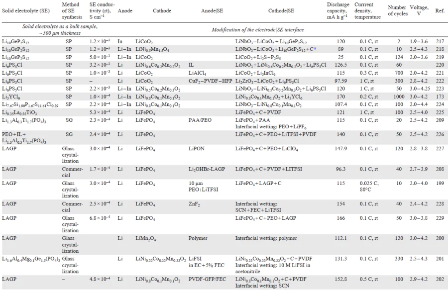
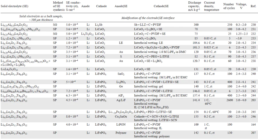
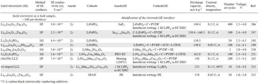
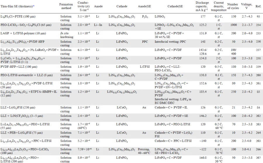
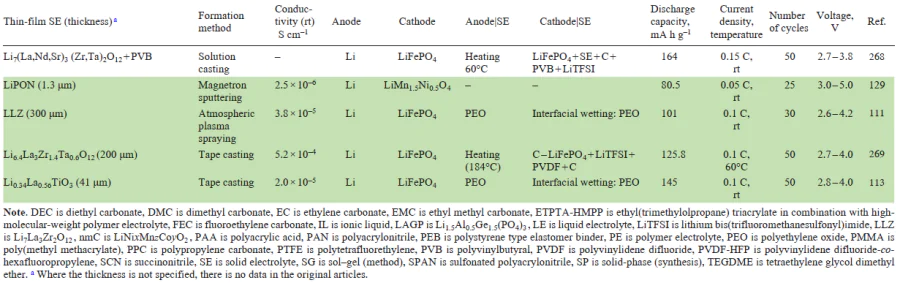
The most common types of all-solid-state cells described in the literature are based on Li anodes, cathode materials traditionally used in lithium-ion batteries (LiCoO2, NMC, LiFePO4), and lithium-conducting solid electrolytes (sulfide or oxide compounds) with a thickness of ~ 500 μm that are described in Section 2.1. According to the data presented in Table 5,Table 6,Table 7(Refs [162][16][173][199-203][206-209][217-236][237-253]), the discharge capacity of assembled cells ranges from 0.3 to 600 mA h g–1 and the current density is from 10 to 100 μA cm–2 for testing temperatures between room temperature and 60°C. The challenges faced in the design of all-solid-state power sources are addressed by modifying the solid electrolyte|electrode interface (Section 3). High performance is, most often, achieved by introduction of a liquid electrolyte traditional for lithium-ion batteries: a solution of lithium hexafluorophosphate (LiPF6) in carbonate mixtures. Table 8,Table 9(Refs [84][85][93][113][129][254-269]) presents characteristics of all-solid-state electrochemical cells with lithium-conducting solid electrolytes formed as thin films. The data available from the literature provide the conclusion that the vast majority of studies are devoted to composite electrolytes that represent a polymer matrix with a ceramic filler or liquid electrolyte (Section 2.2.1). Only LIPON thin-film batteries have become widely used owing to the thoroughly elaborated sputtering procedure for the preparation of this solid electrolyte as a thin film (~ 1 μm). Other types of solid electrolytes are addressed in only few studies, with the assembled cells being cycled 25 – 50 times.[144][264-266] As can be seen from Table 8,Table 9, polymer additives have been used to modify the electrode|electrolyte interface.
4.2. Effect of electrolyte thickness and conductivity on battery performance
The efficiency of thin-film solid electrolytes in Li-ion power sources remains a controversial issue and requires comprehensive analysis. Modelling of batteries reported by Braun et al.[270] showed an increase in the gravimetric energy density and power of the battery as the solid electrolyte thickness decreases from 240 to 1 μm, with the ionic conductivity being invariable. The authors noted that the actual relationships between discharge characteristics and battery parameters may become more complicated because of non-linear effects as the current increases under the operating load, appearance of additional activation polarization of interfacial regions, and diffusion and concentration polarization in the presence of Li+ concentration gradient in a composite electrode.
At the same time, the dependence of specific conductivity on electrolyte thickness follows opposite patterns as reported in various studies. Both an increase and a decrease in the specific conductivity of sulfide and oxide solid electrolytes upon decrease in the thickness have been reported.[32][271] This contradiction can be attributed to specific features of film formation depending on the method, as was discussed in Section 2. In many cases, transition to low-thickness films is accompanied by a decrease in the conductivity of the solid electrolyte in SSB, in particular, this trend can be followed in relation to LLZ thin films (Fig. 11a); an especially pronounced decrease in the ionic conductivity took place for films with a thickness of less than 1 μm.[271] The resulting effect of decreasing thickness of the solid electrolyte can be expressed via the ohmic resistance of the electrolyte ASR = h/σ [Ω cm2], which is the resistance of an electrolyte with conductivity σ [S cm–1], thickness h, and 1 cm2 cross-section. The resulting diagram is shown in Fig. 11b.
![[{"id":"mFZgBRI7sH","type":"paragraph","data":{"text":"Conductivity σ (<i>a</i>) and ohmic resistance ASR (<i>b</i>) plotted <i>vs</i>. film thickness h of LLZ solid electrolyte"}}]](/storage/images/resized/viPCTUdhmCvmwg0XQXlsniVEeHQfqAOdZSnV1R6b_xl.webp)
The data shown in Fig. 11[244][272-279] indicate that decreasing the thickness of a solid electrolyte is an ambiguous solution as regards achieving a lower ohmic resistance of the electrolyte. There may be no correlation between ASR and thickness of the solid electrolyte despite the decrease in the film thickness, since a considerable decrease in the conductivity may occur in thin films. As the film thickness decreases, the influence of both the method and the conditions of film synthesis on the conductivity is enhanced, and most often the conductivity tends to decrease. Thus, it can be concluded that choosing the optimal solid electrolyte thickness in SSBs is an integrated task in terms of improving the power and resource characteristics of the batteries. In addition, a unified approach is needed to determine the critical characteristics of thin-film solid electrolytes such as thickness, conductivity, density, and mechanical properties, the data of which are often lacking.
Section 2 presents examples of thin-film solid elecrolytes of various classes with a thickness from 1 nm to 100 μm for which specific conductivity values characteristic of 500 μm-thick bulk samples were attained. It is of interest to follow the influence of the solid electrolyte weight and crystallographic density on the specific characteristics of the battery. The specific energy capacity of the battery (W, Wh kg–1) can be calculated according to the relation
where C is the power source capacity, A h; U is voltage, V; I is the charge/discharge current, A; t is the charge/discharge time, h; m is the weight of the device, kg.
The reported data on the discharge capacity of a battery take into account only the weight of the cathode material (see Tables 4, 5). However, in the calculation of the specific energy capacity of the battery, in is necessary to include the weights of all components of the device. The weight of the device includes the weights of cathode, anode, the solid electrolyte, and current leads. To calculate the solid electrolyte weight, it is necessary to take into account the electrolyte density and volume. Considering the transfer from a bulk sample (500 μm-thick) to a 10 μm-thick film with the density close to the theoretical one being retained, the weight of the solid electrolyte in the battery decreases 50-fold. For the choice of solid electrolyte for the cells with the same size and geometry, the density of the used material is an important factor affecting the sample weight. In a coin type cell using a solid electrolyte disc of 1 cm in diameter and 500 μm thickness, the solid electrolyte weight is 0.2 g (for LLZ with a density of 5.1 g cm–3) or 0.12 g (for LAGP with a density of 3.1 g cm–3). Thus, on going to the thin-film design, the weight of the LLZ solid electrolyte will be 1.6 times greater than that of the Nasicon solid electrolytes (LAGP, LATP) and 3 times greater than the weight of sulfide solid elecrolytes (Li10GeP2S12, Li6PS5Cl2).
The performed analysis demonstrates the effect of the solid electrolyte thickness and density on the specific energy capacity of all-solid-state battery. However, it is noteworthy that despite the considerable efforts of the scientific community, the design of all-solid-state power source has been implemented all over the world only for LiPON-based batteries, which are characterized by low capacity and rather high costs associated with the deposition of thin-film electrolyte. For other classes of oxide solid electrolytes, similar success has not yet been achieved, and the only solution is to use composite solid electrolytes comprising a polymer matrix with a ceramic filler or liquid electrolyte.
5. Conclusion
This literature review presents analysis of promising lithium-conducting solid electrolytes with various structures applicable for all-solid-state batteries in both bulk and thin-film designs. Currently, active efforts are undertaken with the goal to develop methods for the fabrication of thin-film membranes with a conductivity comparable with the conductivity of bulk samples for most classes of solid electrolytes. Despite the advances made in the field of synthesis and investigation of the properties of promising materials, the integration and implementation of these materials into real electrochemical devices is faced with difficulties since the physicochemical aspects of the used technologies have not been thoroughly elaborated as yet, which also complicates standardization of processes and procedures to enable objective comparison. Analysis of the published data showed the absence of unified certification protocols for the obtained thin-film solid electrolytes, in particular, the lack of data on their mechanical properties. It is noteworthy that the problem of formation of the electrode|electrolyte boundary in an all-solid-state battery also remains relevant on going to the thin-film design. It is necessary to emphasize the importance of formation of the electrode|electrolyte interface particularly in the case of solid electrolyte thin films for which the role of interface increases. The development of an effective design of electrochemical cell can be defined as an important aspect in terms of increasing the discharge capacity and stability of lithium-ion batteries.
The results provide the conclusion that the development and implementation of all-solid-state lithium and lithium-ion batteries requires elaboration of engineering approaches to the formation of half-cells and further assembly of the whole battery. According to analysis of current studies, switching to thin-film electrolytes for SSBs opens up prospects for increasing the discharge power. The following promising research areas in this field can be identified:
— search for new electrolyte materials with high Li-ion conductivity and for electrochemically active electrodes, including high-entropy materials;
— combination of various technologies for the formation of thin-film structures of all SSB components to ensure the formation of a reliable electrode|electrolyte interface with a reduced level of losses;
— organization of an extensive 3D-structure of SSB cells is promising regarding increase in the specific power characteristics and discharge capacity;
— reasonable choice of electrolyte materials in combination with electrodes could be based on the results of physicochemical modelling of transport processes and identification of transport mechanisms in the SSB structure using density functional theory methods for calculating the electronic structure and molecular dynamics.
It is necessary to emphasize the importance of development of new approaches in the combined materials science analysis of the composition – structure – property relationships, engineering solutions, and battery design as a whole. An effective solution to the problems of improving the quality of SSB characteristics can be expected from combined efforts to perform experimental and theoretical studies, develop methods of physicochemical modelling both at the level of electronic structures of materials and on a macroscopic scale of the whole battery. Currently, artificial intelligence (AI) methods offer broad opportunities for data analysis and finding optimal solutions.[280][281] The application of AI methods relies on a large amount of source data, the reliability and representativeness of which are important for ensuring the predictive power of AI models. Neural network methods, including image processing, can be applied in analysis of microscopy data to identify characteristic markers, morphological features, to perform their quantitative characterization, to analyze structural parameters of materials, and determine the correlation dependencies of SSB properties and technological parameters. The utilization of neural networks and other machine learning methods and regression models in the field of SSBs can be directed towards the synthesis of materials with the desired set of electrochemical and thermomechanical properties and the search for new materials to increase the target performance characteristics of SSBs such as battery discharge capacity and stability. Artificial intelligence algorithms can be considered from the perspective of interpreting results of computational experiments using molecular dynamics and atomic-level modelling of transport processes using density functional theory (Fig. 12). It is important to note the importance and ambiguity of interpretation of the AI data and their validation for the strategy of the search for new approaches to the formation of SSB structures.[282]
![[{"id":"EUIXd4UpNa","type":"paragraph","data":{"text":"Schematic path of application of artificial intelligence algorithms for classification and interpretation of the data from experimental studies and numerical experiments"}}]](/storage/images/resized/BRX9884HDpJOkvvbXfHJERM8JgbxAMMQ4DVTU5AU_xl.webp)
The application of artificial intelligence and machine learning methods can bring about additional opportunities for the processing of large arrays of accumulated theoretical and experimental data in order to make more reliable choice for the research strategy, as opposed to the intuitively used trial and error method.
6. List of abbreviations and symbols
Kc — fracture toughness,
ν — Poisson ratio,
HV — Vickers hardness,
σ — flexural strength,
AI — artificial intelligence,
DEC — diethyl carbonate,
DMC — dimethyl carbonate,
EC — ethylene carbonate,
EMC — ethyl methyl carbonate,
EPD — electrophoretic deposition,
ETPTA-HMPP — ethyl(trimethylolpropane) triacrylate in combination with high-molecular-weight polymer electrolyte,
FEC — fluoroethylene carbonate,
IL — ionic liquid,
LAGP — Li1.5Al0.5Ge1.5(PO4)3 ,
LATP — Li1+xAlxTi2–x(PO4)3 ,
LCO — LiCoO2 ,
LE — liquid electrolyte,
LFP — LiFePO4 ,
LIB — lithium-ion battery,
LiPON — lithium phosphorus oxynitride,
LISICON — lithium superionic conductor,
LiTFSI — lithium bis(trifluoromethanesulfonyl)imide,
LLTO — Li3xLa2/3 – xTiO3,
LLZ — Li7La3Zr2O12 ,
NASICON — sodium superionic conductor,
NMC — LiNixMnzCoyO2 ,
PAA — polyacrylic acid,
PAN — polyacrylonitrile,
PE — polymer electrolyte,
PEB — polystyrene type elastomer binder,
PEO — polyethylene oxide,
PMMA — poly(methyl methacrylate),
PPC — polypropylene carbonate,
PPO — polypropylene oxide
PTFE — polytetrafluorethylene,
PVB — polyvinylbutyral,
PVDF — polyvinylidene difluoride,
PVDF-HFP — polyvinylidene difluoride-со-hexafluoropropylene,
SCN — succinonitrile,
SE — solid electrolyte,
SEI — solid electrolyte interface,
SEM — scanning electron microscopy,
SG — sol – gel (method),
SP — solid-phase (synthesis),
SPAN — sulfonated polyacrylonitrile,
SSB — all-solid-state batteries,
SSE — solid-state electrolyte,
SOFC — olid oxide fuel cell,
SSTFBs — all-solid-state thin-film batteries,
TEGDME — tetraethylene glycol dimethyl ether.
References