Keywords
Abstract
Due to significant progress in the development of thin-film deposition technology, the operating temperatures of electrochemical cells with conventional Y2O3-stabilized ZrO2 electrolytes has been substantially reduced. However, the selection of suitable air electrodes for ZrO2-based solid oxide fuel, electrolysis and reversible cells operating at intermediate temperatures (IT, 600–750°C) is still problematic. This issue is related to both insufficient oxygen reduction reaction activity at reduced temperatures characteristic to air electrode materials traditionally used in combination with Y-stabilized ZrO2 in high-temperature devices, as well as the thermomechanical/chemical incompatibility of most state-of-the-art electrode materials with Zr-containing electrolytes. Infiltration is a viable method for fabricating nanocomposite electrodes under mild sintering conditions to avoid mismatch issues. This review adopts an electrolyte-centered approach, offering a comprehensive summary of the progress made in applying the infiltration technique to the development of air electrodes for electrochemical cells with ZrO2-based electrolytes. A review of the performance enhancement of air electrodes with the electrolyte and porous backbones, obtained by infiltrating electron-conducting and mixed ionic-electronic conducting materials, catalytically active oxides and noble metals. The use of infiltration to improve the performance of air electrodes in commercial cells is being explored. The review reveals the excellent benefits of the infiltration technology in designing solid oxide cells that satisfy intermediate temperature criteria, as well as large-scale manufacturing.
The bibliography includes 397 references.
1. Introduction
Solid oxide cells (SOCs) are one of the key technologies for decarbonizing and making energy systems more sustainable due to their advanced electrochemical functionalities.[1-5] Solid oxide fuel cells (SOFCs) are high-temperature energy conversion devices that exhibit superior efficiency (up to 60% and even higher, when using thermal power), fuel flexibility and environmental friendliness.[6-9] Solid oxide electrolysis cells (SOECs) provide the efficient storage of electrical energy produced from intermittent renewable energy sources through the production of ‘green hydrogen’ and renewable synthetic fuels.[10][11]
The main feature of SOC is that it contains a gas-tight oxygen-ion or proton-conducting ceramic membrane as an electrolyte, which separates the fuel and oxidizer compartments. To operate the cell, gases must be supplied to the compartments continuously. The electrolyte membrane is covered with porous electrode layers. These layers are typically composed of a ceramic-metal composite on the fuel (typically hydrogen) side and an oxygen-ion and electron-conducting ceramic layer on the oxidizer (typically air) side. Schemes of the SOFC and SOEC operation with oxygen-ion (typically, stabilized zirconia, doped ceria or lanthanum gallate) and proton-conducting (typically, doped barium (strontium) cerates/zirconate) electrolyte membranes are shown in Fig. 1.
![[{"id":"t06nmiuEO-","type":"paragraph","data":{"text":"Working principles of SOCs with oxygen ion (<i>a, b</i>) and proton-conducting (<i>c, d</i>) electrolytes"}}]](/storage/images/resized/xPUoNpiggVXEmhItjV2SaGSk9cmGTaJ2CLjsw0Ie_xl.webp)
In the case of an oxygen-ion electrolyte membrane (Fig. 1a), in a fuel cell mode, oxygen molecules are reduced at the air electrode (cathode). This forms oxygen ions, which migrate through the oxygen-ion conducting electrolyte to the fuel electrode (anode) due to a gradient in oxygen partial pressure. There, the oxygen ions oxidize the fuel and form water. The difference in chemical potential values between the air and fuel electrodes typically results in a cell voltage, called the Nernst potential or open circuit voltage (OCV), of the order of 1 V. To achieve useful power output, relatively small single SOFCs are connected in parallel and in series in stacks, using ceramic or metallic interconnects and special high-temperature sealants.
In SOEC mode (Fig. 1b), the hydrogen electrode (cathode) is fueled by steam. When an external voltage is applied to the cell, electrolysis occurs, splitting water molecules into hydrogen and oxygen ions. The oxygen ions then migrate through the electrolyte layer to the air electrode (anode), where they are oxidized to produce oxygen, which is the target product in this case.
In a proton-conducting SOFC, hydrogen is oxidized at the anode, generating protons that migrate toward the cathode (Fig. 1c). In this case, the water is generated at the cathode because of a reduction reaction. In a proton-conducting SOEC, steam is supplied to the air electrode side. Only pure, dry hydrogen is produced as a target product at the hydrogen electrode side (Fig. 1d).
A number of comprehensive reviews describe the principles of SOFC and SOEC operation in detail.[12-15]
In order to develop low-cost, high-efficiency, and durable SOCs, efforts have been made to find new materials for the design of SOFC [16-22] and SOEC[22-26] electrodes, electrolytes and interconnectors. Furthermore, the development of nanostructures and their integration into SOC technology has yielded advancements in the creation of functional layers which possess distinctive properties and display superior performance compared to those fabricated by conventional ceramic methods.[15][27-31]
It is known that the operating conditions of the electrolytic membrane and the choice of contact materials (electrodes, sealing materials) are determined by the type of electrolyte membrane material and its functional properties, such as electrical conductivity, coefficient of thermal expansion (CTE), as well as possible chemical interactions with the selected materials.[32][33] Solid solutions based on ZrO2 are known to be the most commonly used electrolytes in high-temperature SOFCs due to their high mechanical strength and negligible electronic conductivity with an ionic transfer number close to unity over the entire range of oxygen partial pressures.[34][35] The use of ZrO2 thin films stabilized with Y2O3 (YSZ) or Sc2O3 (ScSZ) allows the ionic conductivity to be increased by approximately three to four orders of magnitude, providing a solid basis for their use in the intermediate-temperature range.[36-38] Moreover, efforts were made to increase the conductivity and stability of conventional YSZ and ScSZ electrolytes using novel doping strategies [35][39-42] and by creating heterostructures.[43][44] The approaches to modifying electrodes for advanced ZrO2-based SOCs that operate at decreased temperatures include the development of composite,[45-52] nanocomposite,[53-56] dual composite,[57-59] multilayer,[60-63] structured[64-68] electrodes, and electrode composition modification using doping[22][69-75] and high-entropy[17][76-81] strategies. The approaches to increasing efficiency of ZrO2-based SOCs are summarized in Fig. 2.
![[{"id":"m92xO6pF-5","type":"paragraph","data":{"text":"Approaches to enhance efficiency ZrO<sub>2</sub>-based SOCs at decreased operating temperatures"}}]](/storage/images/resized/UzyChcbTDz0OzjuoUIF3mBrGafr66WAGnuxSMtfR_xl.webp)
Unfortunately, highly efficient perovskite electrode materials, developed for operation at reduced temperatures, cannot be directly applied to a ZrO2-containing electrolyte due to their high chemical reactivity during the high temperature sintering in the traditional electrode manufacturing process (typically above 1100°C) and the subsequent formation of insulating phases.[82][83]
To avoid the interfacial reactions when using the perovskite cathodes, a doped ceria, e.g., Gd-doped (GDC), Sm-doped (SDC) ceria buffer layers has to be employed between the air electrode and the ZrO2 electrolyte.[38] However, in addition to the advantages provided by the introduction of such layers, there are some drawbacks.[84] Moreover, their use in SOCs requires additional fabrication steps, which increase the complexity and cost of the cell production.
In addition, there remains the problem of interaction of materials during the formation of composite electrodes, the use of which is often necessary due to the mismatch between the CTEs of electrolytes based on ZrO2 (~ 10 × 10–6 K–1) and barrier layers made of doped CeO2 (~ 12 × 10–6 K–1) with the CTEs of perovskite cathode materials (usually higher than 15 × 10–6 K–1).[83]
The infiltration method, contributing to the operational efficiency of air electrodes, allows the formation of ZrO2-based cells without a buffer layer due to the low sintering temperature of the cathodes (typically 850°C). Furthermore, this method opens up the possibility of using materials with virtually any CTE values.
Infiltration (or impregnation) is a well-known and widely utilized technique for fabricating nanostructured electrodes with improved electrochemical properties.[85] Initially, the focus was on infiltrating highly active and stable metals, such as Pt, Pd, Ir, Ru, Ag, etc., into porous electrode structures. In 1994 – 2003, Watanabe, Uchida et al.[86-88] (the Laboratory of Electrochemical Energy Conversion at Yamanashi University, Kofu, Japan) published a several studies on modifying of anodes and cathodes in YSZ-based cells by the infiltration of highly dispersed metal catalysts. In 2004 – 2006, Gorte and co-workers[89-91] (the University of Pennsylvania, Philadelphia, USA) published several studies on SOFC nanocomposite cathodes formed by infiltration of YSZ-backbones with various catalysts. Later, this group presented several innovative infiltration technologies and studies on long-term stability of the infiltrated systems. In 2006 – 2008, Tucker et al.[92][93] (the Lawrence Berkeley National Laboratory, California, USA) reported first studies on the improved performance of metal-supported SOFCs with infiltrated electrodes. In Russia, the first studies on the improvement of air electrodes using infiltration of PrOx were performed by the group from the Institute of High Temperature Electrochemistry, of the Ural Branch of the Russian Academy of Sciences (Yekaterinburg, Russian Federation), led by B.L.Kuzin and D.I.Bronin[94] in 2009. In 2010, Chen and co-workers[95] (the University of South Carolina, Columbia, USA) presented a study of an electrolysis cell with an infiltrated LSM-YSZ oxygen electrode. In 2014, Hanifi et al.[96][97] (the University of Alberta, Edmonton, Canada) developed redox-resistant fully infiltrated tubular SOFCs. Fan and Han[98] (the China University of Mining & Technology, Beijing, China) studied the electrochemical performance and stability of an infiltrated LSM-YSZ oxygen electrode in a reversible cell. Kiebach et al.[99][100] (the Technical University of Denmark, Roskilde, Denmark) performed a series of long-term stability tests of single cells and stacks with infiltrated electrodes.
Recently, the infiltration technique has gained prominence due to the tendency to reduce the operating temperature of solid oxide cells and the development of technologies for fabricating devices with thin-film electrolyte membranes, which has created a significant demand for improving the electrochemical performance of the electrodes for such devices.[101] In the Russian Federation, the infiltration technique starting from the creation of advanced catalysts for methane reforming[102-105] was successfully applied to develop electrodes for symmetrical cells,[106-109] cathodes[110-115] and anodes[111][114-128] for SOFCs. The appeal of the infiltration technique lies in its simplicity, versatility, and the wide range of materials to which it can be applied. Consequently, over the past 20 years, a number of reviews have emerged that address the application of this technique in SOCs’ technology to fabricate both nanocomposite fuel and air electrodes [85][129-133] and electrode nanoengineering that offer concise summaries of advances in infiltration.[134-141]
However, there are some limitations of the infiltration technique and the infiltrated electrodes. The most significant limitation is the degradation problems caused by the agglomeration of nanoparticles at high operating temperatures. This drawback is especially evident when the metal phase is infiltrated.[99] In terms of fabrication, the infiltration is disadvantageous because the steps of precursor penetration and calcination must be repeated until the desired loading amount is reached. Conventional infiltration technique includes repeating these steps hundreds of times. Nevertheless, the dynamic urea-assisted ultrasonic spray infiltration technique, which was proposed in 2022 by Rehman et al.[142] (Korea Institute of Energy Research, Daejeon, Republic of Korea), and has been further developed by other research groups, allows for the preparation of large-scale infiltrated electrodes (25 – 144 cm2) in three to five infiltration cycles. The combination of urea and an organic fuel, such as glycine, enables the formation of a single-phase perovskite infiltrate at temperatures as low as 650°C.[143] However, using complex multicomponent phases for infiltration remains challenging. Fig. 3 provides an overview of the advantages and disadvantages of the infiltration technique, potential solutions and a timeline of the most significant related research.
![[{"id":"NjutQheoGk","type":"paragraph","data":{"text":"Infiltration pros and cons, possible solutions, related research"}}]](/storage/images/resized/aH0EzaUImgepO5Xi06IQjZnximD61QBGeLSyqIIM_xl.webp)
Infiltration can be defined as the process of a liquid permeating a solid material through filtration. Typically, it includes three sequential steps: the formation of a porous backbone, the introduction of a liquid precursor solution into its structure and the subsequent application of heat treatment. At each stage of the process the specific controllable parameters must be considered. At the initiation stage, the following issues are imperative: (1) conductive nature of the backbone; (2) the structure (bilayer or multilayer) and microstructure of the backbone, which is defined by the dispersity of the powders and the type of the pore former used, as well as the formation method and sintering conditions. The preparation of a precursor solution is subject to several controllable parameters, including: (1) the selection of solution media; (2) the choice of an optimal concentration; (3) the introduction of chelating agents, which plays a crucial role in facilitating the formation of a single-phase state of the infiltrated material; (4) the introduction of surfactants, which is essential for regulating the backbone wettability. The subsequent heat treatment allows the production of nanosized particles of the material introduced by infiltration. The sintering temperature and dwelling time, controllable parameters in this final step, have a significant influence on the size, crystallinity and grain growth of the particles. It should be noted that this step can be omitted and infiltrated electrodes can be sintered in situ, during the entire cell heating and measurements.[144] Fig. 4 summarizes the parameters to be controlled at every stage of the infiltration process.
![[{"id":"1DPz2qIePF","type":"paragraph","data":{"text":"Controllable parameters of the infiltration process"}}]](/storage/images/resized/pMDs3QIROnrRGONcQfUTbdqoHB1u8CLnLw7wvqsV_xl.webp)
According to the backbone conducting nature three classes of SOFC electrodes can be distinguished:[145] (1) porous electrolyte backbones with infiltrated electrocatalyst; (2) single-component mixed ionic electronic conductor (MIEC) backbones; (3) composite electrodes backbones.
It is widely recognized that the electrolyte type significantly impacts the selection of contact materials (such as electrode and sealing materials) and the operational characteristics of the cell. Nevertheless, to the best of our knowledge, this review is the first to implement an electrolyte-centered approach to summarize the progress made in applying the infiltration (or impregnation) technique to the development of air electrodes for electrochemical cells with ZrO2-based electrolytes. Extensive information on the infiltrated electrodes on the base ZrO2 electrolyte backbones and related composites for the purpose of lowering the operating temperature are presented. In addition, attention is given to the infiltration of air electrodes with electron-conducting or mixed ionic-electronic conducting backbones, used in commercial SOCs with ZrO2-based electrolyte membranes. Factors that can be critical to the infiltrated electrode performance, such as backbone content and microstructure, solution concentration, presence of additives, number of cycles and loading level, intermediate and final heat treatment temperatures of the infiltrate to obtain single-phase nanosized particles or films, are considered. Due to the sensitivity of electrode performance to numerous factors, direct comparison of electrodes prepared by different research groups, even when using the same composition and formation conditions, is quite difficult. Therefore, the promotion factor[136][146] has been used to evaluate the effect of infiltration on the polarization resistance of a series of samples, including a reference one, within a given study:
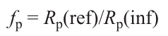
where Rp(ref) and Rp(inf) are the polarization resistance values for the reference electrode and the electrode, modified by infiltration. The use of the factor values allows a more precise evaluation of the results obtained with different backbones, infiltrate compositions, and infiltration techniques. Special attention has been given to short- and long-term stability issues as they are most prominent in nanoscale systems. Scalable infiltration methods have also been briefly considered as a solid base for the implementation of this advanced technique in commercial devices.
2. LSM-YSZ nanocomposite electrodes prepared by infiltration
2.1. Impact of infiltration types, additives, loading level and sintering conditions on the electrode performance
The infiltration technique, which involves the formation of the micro-sized electrolyte backbone followed by loading it with a catalyst, typically electronic or MIEC material, on the submicron level, is a frequently utilized technique that offers several advantages. Firstly, elevated sintering temperatures of the electrolyte backbone ensure optimal adhesion between the electrode/electrolyte interface and structural stability of the electrode. Secondly, this method circumvents the challenge of CTE matching between the cathode and the electrolyte. Thirdly, the size of infiltrated catalyst particles can be controlled at the nanometer level, allowing for the generation of numerous reactive zones which can enhance electrode performance significantly. Furthermore, the fabrication by infiltration significantly reduces the percolation threshold of the electronic (MIEC) phase, enabling the attainment of the desired electrical properties with reduced catalyst loadings.[147][148] Taking into account these advantages, the most recent works were directed to the formation and study of the infiltrated electrodes based on YSZ backbones.[89][90] [149][150] However, since electrolyte backbone provides only an ion-conducting pathway, thus the infiltrated material should enable global electron supply as well as electrocatalytic sites within the bulk of the electrode.[145]
The standard cathode material used in SOFCs with YSZ electrolytes is Sr-doped LaMnO3 (LSM) because of its high electronic conductivity (200 – 500 S cm–1 at 800°C (Ref. [151])) and CTE values (11.4 – 13.2 × 10⁻⁶ K–1 (Ref.[152])) the closest to those for YSZ and ScSZ. However, the lack of ionic conductivity of LSM (10–4 – 10–8 S cm–1 (Ref.[153])) limits the overall reaction rate due to a restricted length of the triple phase boundary (TPB). Consequently, the development of LSM-YSZ composite electrodes was seen as one possible way to increase TPB and enhance the electrochemical performance of manganite-based electrodes.[45] In particular, infiltrating LSM into a porous YSZ structure has been used for the modification of air electrodes of symmetrical,[91]fuel,[92] [154-162] electrolysis[95] [163][164] and reversible[98] cells.
The critical factors that influence the improvement of electrode performance using the infiltration strategy include the catalyst loading level, catalyst composition and particle size, surface decoration with discrete particles or films, and the uniformity of the catalyst distribution throughout the backbone volume.[130] There have been three basic methods for infiltrating a catalyst into the electrolyte backbone presented in literature. The most common method is infiltration with metal-salt nitrate solutions with or without various additives (surfactants such as Triton X-100,[154][165][166] Triton-X-45,[92] Pluronic P123;[167] organic fuels such as citric acid,[163] [166] [168-170] ethylenediaminetetraacetic acid (EDTA),[171]glycine,[172]ethylene glycol[155] [173] and their mixtures). To minimize deposition nonuniformity, a secondary material such as urea, a highly dissolvable organic compound, can be added to the metal salt solution to induce precipitation before evaporation of the solvent.[130][142][143][174] Zhu et al.,[175] Burye and Nicholas,[165]Dowd et al.[176] studied the effect of various surfactants, chelating agents, and pH on the performance of infiltrated SOFC cathodes. Ethanol can also be added to the infiltration solution to improve the wetting ability of the electrolyte backbone.[177][178] Alternatively, internal electrode surfaces can also be treated to promote infiltration with various catechol surfactants such as poly-norepinephrine,[179] poly-dopamine,[180] etc.
Two other less developed methods are impregnation with nanoparticles from a suspension[156][181] and molten salt impregnation.[156-158] [182][183] Using concentrated precursor solutions reduces the number of infiltration cycles. However, this strategy has the potential disadvantages of inhomogeneous deposition and pore-clogging, which result in gas diffusion limitations in the electrode.
In 2005, Huang et al.[91] were the first to describe the properties of LSM-YSZ nanocomposites, prepared by infiltrating an aqueous (La, Sr, Mn) nitrate solution into a YSZ backbone. The impregnation steps were repeated 4 – 5 times with the intermediate sintering at 450°C to achieve the loading of 40 wt.% of LSM. The resulting composite, sintered at 850°C, consisted of small crystallites of the impregnated phase (< 0.1 mm) covering the YSZ pores. The polarization resistance (Rp) measured at 700°C, increased with the increasing the final sintering temperature of the nanocomposite from 0.48 Ω cm2 (900°C) to 4.6 Ω cm2 (1100°C), and to 6.4 Ω cm2 (1250°C). This was due to a decrease in the electrode surface area and, finally, due to the appearance of a dense LSM layer (which has a poor ionic conductivity [153]) on the electrolyte surfaces, restricting the diffusion of oxygen ions. The interfacial reaction between LSM and YSZ at 1250°C with the appearance of a La2Zr2O7 insulating phase was also observed. The polarization values decreased to 2.6 and 3.8 Ω cm2 after reduction in humidified H2 or by cathodic polarization due to the introduction of microporosity in the LSM films.
Furthermore, Huang et al.[156] compared the above method with two alternative approaches to achieve a loading of about 40 wt.% LSM. It was found that the impregnation with a colloidal dispersion of LSM nanoparticles in 1,4 butanediol required an even greater number of impregnation steps (14 – 20). The final sintering temperature of the composite was chosen to be 1050°C. The use of molten nitrates for the impregnation allowed the attainment of a loading of 35 wt.% LSM precursor to be achieved in only two impregnation steps. The final calcination temperature was also 1050°C. The authors suggested that the relatively high mobility of LSM on YSZ, coupled with surface interactions, causes the final composite structures to be essentially identical irrespective of the method by which LSM was introduced (Fig. 5a). The anode-supported cells comprising the cathode, although made using different infiltration techniques, demonstrated approximately the same power output (Fig. 5b). All the infiltrated LSM-YSZ composites exhibited polarization resistance between 0.4 and 0.5 Ω cm2 (at 700°C). However, the absence of a solvent in the infiltration of molten salts eliminates the necessity for solvent removal, thereby ensuring a more uniform LSM particle distribution within the YSZ backbone and, consequently, better performance stability.
![[{"id":"uLqUDnrU8G","type":"paragraph","data":{"text":"(<i>a</i>) SEM images of the LSM-YSZ nanocomposites prepared by infiltration of the metal nitrate solutions, LSM nanoparticle suspension and molten salts.<sup>91, 156</sup> Copyright belongs to the Electrochemical Society; (<i>b</i>) the electrochemical properties of the composites tested at 700°C on the anode-supported cell with a 60 μm YSZ electrolyte.<sup>156 </sup>Copyright belongs to the Electrochemical Society; (<i>c</i>) SEM image of the structure of the MS-SOFC of symmetrical design, consisting of a thin electrolyte and two porous cathode and anode backbones for subsequent cathode and anode impregnation, sandwiched between porous metal support layers.<sup>157 </sup>Copyright belongs to Wiley; (<i>d</i>) XRD patterns of the decomposition products from LSM precursors sintered at 800°C for 1 h with and without Triton X-100 additive. Peaks corresponding to the perovskite phase are indicated by dotted lines.<sup>154 </sup>Copyright belongs to the Electrochemical Society; (<i>e</i>) average particle size of infiltrated LSM nanoparticles, sintered at 900 and 1100°C before and after polarization at 0.5 A cm<sup>–2</sup> at 800°C for 100 h.<sup>163 </sup>Copyright belongs to Elsevier."}}]](/storage/images/resized/oaKgrPVW3fJ6moEelqOrSADGEcMwvLhuvCir7SWG_xl.webp)
The molten salt infiltration was further developed for anode-supported SOFCs [159] and metal-supported SOFCs (MS-SOFCs) of symmetrical design (see Fig. 5c).[92][158][160][161] For instance, Tucker[57] reported peak power density (PPD) values of 0.44, 1.1, and 1.9 W cm–2 achieved at 600, 700, and 800°C, respectively, for an optimized cell with the LSM-YSZ nanocomposite cathode obtained by molten salt infiltration.
Preparation and long-term stability of nanocomposite Ni-YSZ and LSM-YSZ electrodes prepared by infiltration of polymeric precursors were investigated by Buyukaksoy et al.[155] Particularly, the LSM precursor was prepared by the addition of ethylene glycol and 2-butoxyethanol to a metal nitrate aqueous solution in a molar ratio to the metal cations equal to 0.04 : 0.04 : 1. Interestingly, the LSM precursor was infiltrated through the Pt layer, pre-deposited on the YSZ backbone (15 mm) and sintered at 800°C. Twenty infiltration steps were performed to obtain a sufficiently high LSM content (~ 35 wt.%). The single cell with the supporting YSZ electrolyte (170 mm) and infiltrated cathode achieved PPD of 0.49 W cm–2 at 800°C and showed degradation of about 15% in the first 60 hours and no further degradation up to 110 hours.
Sholklapper et al.[154] showed that the addition of Triton X-100 to the nitrate solution allows a reduction in temperature of the single-phase LSM phase formation in the YSZ-based composite down to 800°C (Fig. 5d ) and obtaining enhanced electrode performance after a single infiltration step. Despite the low LSM loading (6 wt.%), PPD of the anode-supported cell with a thin-film YSZ electrolyte (13 mm) and the infiltrated cathode reached 0.27 W cm–2 at 650°С. For the cathode performance of the developed cell, a factor fp equal to 37.9 was achieved compared to that of a Pt cathode. In a follow-up study,[159]the authors used a vacuum-assisted single-step infiltration of a highly concentrated LSM nitrate solution with Triton X-100 additive to obtain Zr0.9Sc0.1O1.95 (SSZ)-LSM nanocomposites with final sintering at 900°C. The resulting electrode showed stable performance over 500 h of operation at 650°C, under a nearly constant applied current density of 0.15 A cm–2, with minimal coarsening of the impregnated nanoparticles.
Tucker et al.[92] achieved the high PPD values for tubular MS-SOFCs by infiltrating a porous YSZ backbone on both the anode and cathode with nitrate salt solutions (Ni, Ce) and (La, Sr, Mn) with the addition of Triton-X-100 or Triton-X-45 at a surfactant loading of 0.3 g per 2 g of resulting catalyst particles. The impregnation steps were repeated ten times on the anode. Only two infiltration cycles were required to obtain the optimum LSM loading of 15 vol.% (~ 35 wt.%). Power densities of 0.726, 0.993 and > 1.3 W cm–2 were achieved at 0.7 V at 650, 700, and 750°C, respectively, using pure oxygen as the oxidant and wet hydrogen as the fuel. The air-supplied cell exhibited 0.233 W cm–2 at 0.36 A cm–2. In practice, SOFC power systems experience constant fluctuations in operation due to varying power demands. The developed tubular MS-SOFCs with the infiltrated YSZ-LSM air electrode were tested in a dynamic temperature operation mode, in which the cell temperature varies rapidly from 675 to 800°C or from 670 to 720°C.[162] The current density increased from 0.82 to 1.95 A cm–2 in 6.6 min at 675 – 800°C and from 1 to 1.63 A cm–2 in 5.4 min at 670 – 720°C. The cells were subjected to continuous dynamic temperature cycling for more than 100 cycles. The degradation rate was 1.5 and 0.25% h–1, respectively, over the entire operating time. It should be noted that the degradation rate of LSM-YSZ composites is strongly dependent on the applied current, therefore, it can be substantially decreased at lower current densities[93] [184]
The sintering and grain growth of LSM particles behave very differently under cathodic and anodic polarization conditions.[185] It is known that under cathodic polarization, the performance of the LSM cathode improves due to surface and phase boundary activation, enhanced surface exchange kinetics, and expansion of the active reaction zone. In contrast, under anodic polarization, performance degrades due to the oxidation of manganese ions and the formation of manganese cation vacancies, leading to lattice shrinkage, which may cause excessive internal stress and electrode delamination.[186-188] It was shown that infiltration is a promising technique to solve the existing delamination problem of LSM-based electrodes in SOEC mode. Yang et al.[95] were the first to investigate the LSM-YSZ nanocomposite oxygen electrode prepared by cyclic infiltration of aqueous nitrate solution (40 wt.% loading) for the high-temperature water electrolysis. No deterioration of the electrochemical performance was observed after electrolysis at 800°C and a current density of 0.330 A cm–2 for 50 hours at 50 vol.% humidity.
Chen et al.[163] studied the stability of the nanostructured LSM-YSZ electrodes prepared by infiltrating a YSZ backbone with a LSM nitrate solution with the addition of citric acid (~ 45 wt.% loading) under a constant anodic current of 0.5 A cm–2 at 800°C for 100 h. It was found that the microstructural stability of LSM nanoparticles is governed by two opposite effects: one is the grain growth by the thermal coarsening effect and the other is the LSM lattice shrinkage under the anodic polarization. The dominant process is defined by the initial particle size of the infiltrated LSM. As shown in Fig. 5e, for the electrode, heat-treated at 900°C and having an initial average nanoparticle size of 66 ± 18 nm, the thermal coarsening effect is dominant, as indicated by the increase of LSM nanoparticles after an anodic polarization test. On the other hand, for the electrode heat-treated at 1100°C with an initial average nanoparticle size of 157 ± 34 nm, the lattice shrinkage effect is dominant, supported by the decrease of the LSM particle size after anodic polarization. In both cases, the infiltrated electrodes showed excellent stability during 100 h compared to the conventional LSM-YSZ electrodes, which revealed a significant increase in the electrode polarization and ohmic resistances under similar anodic current loading conditions during 48 h.[186]
Furthermore, it was shown that GDC infiltration into the LSM anodes not only enhanced the electrocatalytic activities for the oxygen reduction reaction (ORR), but also effectively inhibited the delamination of the LSM electrode at the LSM/YSZ interface.[189]According to the authors, the infiltrated electrode is supposed to behave as a mixed ionic electronic conductor rather than an electronic conductor (EC). The oxygen diffusion and formation processes take place mainly on the impregnated GDC phase, while LSM plays a role mainly for the electron transfer path. This idea was supported by the stability of the ohmic resistance values of the GDC-LSM anodes under the current density of 0.2 and 1 A cm–2 for 22 h.
Fan et al.[164] observed an insignificant voltage increase (0.24 mV h–1 at 800°C during 900 h) without delamination for SOEC with the conventional LSM-YSZ electrode infiltrated with SrFe2O4 – δ , while the reference cell showed a voltage increase of 1.68 mV h–1 during the first 200 h of the SOEC operation. However, a sharp voltage increase was observed after 300 h of operation, until complete delamination after 350 h. The difference in Rp between the reference and infiltrated cells became as high as 20 times after 240 h of operation. SrFe2O4 – δ infiltration was shown to significantly mitigate the formation of secondary phase particles and the associated delamination at the LSM/YSZ interface. It was also observed to lead to the formation of Fe-doped LSM catalytic nanoparticles on the surface of the LSM and YSZ backbone, introducing additional new triple phase boundaries to expand the electrochemical reaction sites.
Fan and Han[98] explored the application of LSM-infiltrated YSZ oxygen electrodes for reversible SOCs. In a fuel cell mode, the cell with a thin-film YSZ electrolyte (20 μm) exhibited PPD of 0.726 W cm–2 and Rp of 0.21 Ω cm2 at 850°C. In an electrolysis mode, the current density of 1 A cm–2 was achieved at an electrolysis voltage of 1.35 V. The performance of the fuel cell (1 h)/water electrolysis (1 h) cycle showed only slight degradation over 6 cycles.
2.2. Impact of the electrolyte backbone microstructure
The microstructure of the electrolyte backbone determines both the distribution of the solution and the size of the resulting infiltrated particles.[190] In addition, the network of the electrolyte particles also controls the transport of oxygen ions from the electrolyte and oxygen molecules in the porous electrode.[191] Higher porosity has been shown to facilitate deep penetration and uniform distribution of the infiltrated catalyst, thereby increasing the active surface area and the TPB density. However, excessive porosity has been found to decrease ionic conductivity due to a reduction in electrolyte material volume and to degrade the mechanical integrity of the electrolyte backbone. Reduced porosity improves ionic conductivity and mechanical strength, although it can impede catalyst infiltration and gas diffusion which could potentially limit the electrode performance. Therefore, it was critical to maintain the optimal pore characteristics for the electrolyte backbone to balance the competing requirements as provided in studies.[192-200]
The effect of the YSZ backbone microstructure on the performance of the infiltrated LSM electrodes has been investigated by Torabi et al.[192] The porosity of the electrolyte backbone reached 50 – 55% using both as-received (YSZ (Tosoh), 12.3 m2 g–1) or calcined-milled YSZ (CYSZ, 3.2 m2 g–1) powders, pore formers (polymethyl methacrylate (PMMA), graphite and carbon black), and the sintering conditions (1200 – 1350°C). Infiltration was carried out from the nitrate solution with addition of citric acid and ethylene glycol taken in the ratio of 4 : 4 : 1 to metal cations. The single-phase LSM was thus obtained at 700°C. Examples of the electrode structures before and after infiltration are shown in FIg. 6a. It was found that the electrodes with PMMA based on the calcined powder CYSZ showed a more uniform morphology with spherical pores of PMMA interconnected with randomly shaped cavities of calcined YSZ particles. The addition of mixtures of micro- and nano-sized pore formers improved the electrode performance due to the extended TPB. The lowest Rp value of 0.06 Ω cm2 at 800°С was obtained for the YSZ-PMMA-G electrode. The authors noted that the use of a pre-calcined YSZ powder was advantageous in terms of better adhesion to the electrolyte and stability of the electrode performance. It was also shown that infiltrated cells with cathode thicknesses of 20 – 40 μm worked better than those with 10 – 15 μm thickness, despite having a similar LSM-YSZ weight ratio, probably due to the additional reaction zone available.[168]
![[{"id":"0b1BqNbU9e","type":"paragraph","data":{"text":"(<i>a</i>) SEM images of the electrolyte backbones prepared using as-received YSZ (Tosoh, 12.3 m<sup>2</sup> g<sup>–1</sup>) or calcined-milled YSZ (CYSZ, 3.2 m<sup>2</sup> g<sup>–1</sup>) powders and different pore formers (polymethyl methacrylate (PMMA), graphite (G) and carbon black (C) (top line), sintered at 1200 – 1300°C, and the electrodes on their base infiltrated with LSM (bottom line).<sup>192 </sup>Copyright belongs to the Electrochemical Society; (<i>b</i>) directional pattern formation and particle segregation during freeze-casting of a ceramic slurry. The ice platelets grow in a direction perpendicular to the c-axis of the hexagonal ice. The wavelength of the structure is defined by the parameter λ.<sup>199 </sup>Copyright belongs to Acta Materialia Inc.; (<i>c</i>) SEM image of the unit cell of a SOFC/SOEC stack designed by NASA using freeze-tape-cast YSZ electrodes 200; (<i>d</i>) the schematic of the fabrication process of the nanostructured cathode and (<i>e</i>) cross-sectional SEM images of the entire single cell with zoomed-in LSM-infiltrated YSZ nanofibers (yellow) and LSM-infiltrated YSZ powder layer (blue).<sup>196 </sup>Copyright belongs to Wiley."}}]](/storage/images/resized/z5xfXdCNhiAtDfx9h62oSQfw2woL6dy9h1ck69dY_xl.webp)
Cassidy et al.[197] regulated the porosity of YSZ electrode backbones fabricated via aqueous tape casting using various combinations of rice starch, PMMA (8 μm), polyethyl methacrylate (PEMA) (35 – 45 μm) and latex. The total pore area of the samples sintered at 1400°C was found to increase from 6.5 to 17% with the addition of 20 vol.% rice starch. However, it was unsuitable for the infiltration. The optimal porosity of 53.3% was achieved using a combination of 14 vol.% of rice starch, smaller PMMA (15 vol.%) and large PEMA (15 vol.%) particles and addition of 20 vol.% of latex. This work demonstrates that targeted porosity comes from the pore formers rather than residual porosity. However, using finer YSZ powder results in tighter and stronger sintering of the ceramic phase around the pores.
Maide et al.[198] studied the conditions for forming three-layered structures comprising a thin-film, dense ScCeSZ electrolyte layer sandwiched between two porous electrolyte backbones, which are suitable for infiltrating anode and cathode catalysts. The authors combined two different approaches to prepare backbones of various porosities: (1) pre-sintering the electrolyte powder to influence its particle size distribution and (2) adding a controlled amount of carbon-based pore formers with different particle size distributions. For a 59% porous backbone obtained from untreated commercial ScCeSZ powder with the addition of 15 wt.% lamellar graphite and 15 vol.% activated carbon, the loading of 30 wt.% of catalyst resulted in limited gas transport, indicating the potential presence of closed pores and/or small pores that are virtually inaccessible for infiltration. Substituting 90 wt.% of unsintered electrolyte powder with pre-calcinated one (at 1300°C) increased the porosity of the scaffold by approximately 10%. However, using pre-calcinated electrolyte powder with the increased particle sizes decreased the specific area of the electrolyte backbones and catalytic activity of the related electrodes at low catalyst loadings (10 – 20 wt.%).
Guillon et al.[201] performed the optimal selection of the microstructure and thickness of ZrO2-based functional layers (both dense and porous) using conventional and advanced coating technologies. Reszka et al.[202] presented a mechanistic model for the predicting the total and active TPB density and the effective conductivity of infiltrated electrodes. The use of this model showed that the backbone : infiltrate particle size ratio has the greatest impact on the TPB density, followed by the porosity and then the pore : infiltrate size ratio. The TPB density is shown to monotonically decrease with increasing backbone : infiltrate and pore : infiltrate size ratios. However, it shows a maximum with respect to porosity. For instance, at 45% porosity, the maximum active TPB density occurs at the loading of 28 vol.%, at 65% porosity — at an infiltrate loading of 34 vol.%, and for 85% porosity — at an infiltrate loading of 43 vol.%. The effective conductivity that corresponds to the maximum active TPB density ranges from 3 to 6% of the bulk conductivity of the electronic conducting material used for infiltration. Decreasing the infiltrate particle size increases the TPB density. For example, a particle size decrease from 100 to 25 nm will increase the TPB density by a factor of 16. However, an increase in the nanocatalyst surface area also increases the driving force for coarsening and sintering mechanisms. Therefore, nanoparticle stability during operation is a major challenge for infiltrated systems.
In 2025, Yildirim et al.[193] carried out a comprehensive study on the influence of various parameters such as the YSZ backbone thickness (25 – 75 mm), infiltration solution concentration (0.5 M – 2 M), the number of infiltration cycles (up to 5 for 2 M, 10 for 1 M and 20 for 0.5 M), and infiltrate sintering temperature (800 – 1000°C) on the microstructure and electrochemical performance of the YSZ-LSM nanocomposite electrodes. Maximum total LSM loadings of 6.1 and 13.7 mg cm–2 were obtained for 25 and 50 mm thick porous electrolytes, respectively. The increased LSM catalyst content enhanced the TPB density. However, thicker backbones resulted in higher ohmic and cathode gas diffusion resistances and relatively lower cell performances. Therefore, the optimal results based on electrochemical performance (0.546 W cm–2 at 800°C) were achieved with 13 infiltration cycles of a 0.5 M LSM solution into a 25 μm thick, porous YSZ backbone, with a final sintering temperature of 1000°C. The reference cell with the conventional YSZ-LSM cathode exhibited only 0.172 W cm–2 under the same conditions.
The number of infiltration cycles can be substantially decreased using modified backbone structure. For example, freeze-casting has been shown to be a viable method for fabricating electrodes with hierarchical porosity, thereby increasing the TPB area while ensuring sufficient gas flow.[194][200][203-206] FIg. 6b shows the patterns of directional porous structure formation during the process.[199] In the freeze-casting process, the particles in suspension within the slurry are ejected from the moving solidification front and subsequently accumulate between the growing columnar or lamellar ice. Since solidification tends to be directional, the porous channels are oriented from the bottom to the top of the samples. Therefore, freeze-cast structures offer several advantages, including low tortuosity and high porosity, which allows for rapid gas diffusion. They have straight pore channels, which makes them very suitable for infiltrating catalysts.[207]
Cable and Sofie[194] reported a bi-electrode supported cell with porous YSZ backbones fabricated using freeze-tape casting on each side of a 10 – 20 mm electrolyte. The symmetrical cell design offered several notable advantages. For example, it simplified the co-firing process by creating a uniform stress field for the thin electrolyte in the centre. Because fuel and air circulate through thick scaffold electrodes, the interconnect does not require integral gas flow channels, and its thickness can be greatly reduced. The thick YSZ electrode scaffolds with graded porosity require multi-stage infiltration. However, it can be performed with the reduced intermediate (400°C) and final (600°C) sintering temperatures. The SEM image of a bi-electrode supported cell with porous YSZ backbones is given in FIg. 6c. Details on the formation of the freeze-cast YSZ pore network can be found in the study.[200]
Wu et al.[208] utilized freeze casting and infiltrating to fabricate a novel biomimetic honeycomb SOEC air electrode with low tortuosity factor, combining high porosity (75%) and excellent structural strength. At the freezing temperatures of –60°C, the YSZ backbone possessed less than 4 μm thick fine pores in the bottom and more than 10 μm thick large pores in the top, resulting in an ideal gradient honeycomb morphology. The ultimate compressive strength of the honeycomb electrode exceeded 502.9 N, which was 13 times higher than that for the conventional electrode. With 27 wt.% lanthanum strontium cobaltite (LSC) loading, the nanocomposite LSC-YSZ electrode demonstrated Rp equal to 0.0094 Ω cm2 with fp of 11.7 compared to the blank LSC electrode. A three-electrode cell with the developed honeycomb composite electrode showed stable current density of 1.5 A cm–2 for 4 hours, and no obvious performance degradation at 2.0 A cm–2 for 6 h at 800°C.
Electrodes based on one-dimensional (1-D) nanofibrous structures were shown to exhibit outstanding performance, providing new ideas for developing electrode materials suitable for intermediate and low temperatures.[209-211] In particular, such materials can be obtained by electrospinning.[212-214]
Zhi et al.[195] synthesized 1-D YSZ nanofibers by electrospinning, to be used for the YSZ electrolyte backbone formation with the following infiltration with LSM. The use of 1-D fibres offers several advantages. First, the nanofibres naturally form a highly porous scaffold without further addition of pore formers. Second, only a single infiltration step is required to achieve a high loading level in the nanofiber backbone. Third, the interconnected LSM nanoparticle network is easily formed on the YSZ nanofibres, resulting in a nanoporous LSM shell on the YSZ nanofiber core. The YSZ nanofibers were deposited on the YSZ electrolyte and sintered at 800°C to obtain a backbone structure. LSM was infiltrated from a 1 M solution of (La, Sr, Mn) acetates in N,N-dimethylformamide with the addition of 6% polyacrylonitrile. After infiltration, the samples were rapidly heated to 280°C, held for 1 h and finally sintered at 650°C. Loadings of 25, 50 and 75 wt.% were achieved after 1, 2 and 3 infiltration cycles. The fast ion transport in the continuous fiber network and an increased number of triple-phase boundary sites were considered to be the reasons for the high performance of the infiltrated LSM-YSZ composite electrode with 50 wt.% LSM loading (0.48 and 0.27 Ω cm2 at 700 and 800°C, respectively).[195]
Kim et al.[196] designed nanostructured cathodes with exceptional performance using a YSZ nanofiber backbone. The schematic of the formation of the anode-supported cell with nanofiber-based cathodes and the SEM image of the cell are shown in FIg. 6d and FIg. 6e, respectively. The bonding layer between the electrolyte and the nanofibre backbone with a sintering temperature of 800 – 1200°C allowed sufficient adhesion of the entire electrode structure to the electrolyte, while the calcination of the LSM solution was performed at 800°C. The nanocomposite electrode with the lowest sintering temperature (800°C) exhibited specific surface area and oxygen vacancy concentrations 8.1 and 1.6 times higher than those sintered at 1200°C, respectively. The cell with optimized cathode parameters showed PPD of 2.11 and 1.09 W cm–2 at 700 and 600°C, respectively, and excellent stability for 300 hours under 1.5 A cm–2 at 750°C.
2.3. Microtubular cells with YSZ-LSM nanocomposite electrodes
Among various SOFC configurations, microtubular SOFCs (μT-SOFCs) stand out with their distinctive features: easy sealing, quick start-up, good thermo-cycling behaviour and high thermal shock resistance. They combine the advantages of a tubular geometry and compact size. Because the active surface area per unit volume is inversely proportional to the cell diameter, μT-SOFCs have a remarkably high volumetric power density, making them an appealing choice for portable power generation. However, μT-SOFCs face main challenges: their low current collection efficiency and reduced performance at decreased temperatures, particularly when employing conventional Ni-YSZ, YSZ and LSM cell components. To improve the μT-SOFC performance, the infiltration technique was successfully applied to cathodes,[215][216] anodes,[217][218] both electrodes[96][168] [219] and current collectors.[220] The presence of finely dispersed infiltrates enhances catalytic activity, while the interconnected particles with a large surface area act as conductive pathways. This improves the cell performance and reduces the operating temperature. This, in turn, reduces degradation. Additionally, the reduced amount of catalyst needed for the effective operation of infiltrated nanocomposite electrodes, compared to traditional counterparts,[221] helps to significantly reduce stress in the μT-SOFC structure, thereby minimizing delamination issues.
For example, Howe et al.[168] managed to improve the performance of the anode-supported μT-SOFCs with a 10 mm thick YSZ electrolyte via infiltration of different cathodes and anodes. Particularly, the LSM-YSZ nanocomposite cathodes were obtained by a hot infiltration technique into the porous YSZ backbone (15 – 30 mm thick) with different porosity controlled by using graphite or PMMA. Triton X-45 was added as a dispersing agent to an aqueous nitrate solution heated to 100°C prior to infiltration. The process was repeated twice with an intermediate calcination at 150°C. The total LSM loading varied from 26 to 35 wt.% depending on the backbone thickness and pore former used. Cells with the cathodes formed with PMMA exhibited slightly lower cell resistance (0.48 – 0.54 Ω cm2, at 700°C) than those formed with graphite (0.49 – 0.62 Ω cm2). This study also showed that even a small quantity of SDC (2.5 wt.%) or Ni-SDC (3.5 wt.%) infiltrated to the anode resulted in a significant increase in power density and cell stability. Thermal cycling at 100°C min–1 resulted in an average power degradation of 10% over 56 cycles, while the reference cells showed a degradation of 13%. The power degradation was shown to be mainly due to electrode changes, rather than electrolyte cracking, as the OCV did not decrease significantly.
Laguna-Bercero et al.[215] investigated the effect of the LSM loading to the YSZ backbone on the performance of the anode-supported μT-SOFCs. Graphite (20 vol.%, 8.6 wt.%) was added to the YSZ slurry to ensure sufficient porosity (50%) of the YSZ backbone (~ 40 µm), which was deposited on the sintered YSZ electrolyte (~ 15 mm) by dip coating followed by a step calcination at 300, 700 and 1350°C. The infiltration was performed according to the well-developed hot infiltration procedure.[97][168] Two cells were prepared with 22 vol.% and 35 vol.% infiltrated LSM. These loading levels resulted in a reduction of the cathode layer porosity down to 36 and 23%, respectively. The cells with infiltrated electrodes showed 0.230/0.615 and 0.245/0.700 W cm–2 at 0.7 V and at 700/800°C, which was up to 50% higher compared to the reference cell.
However, due to their tubular geometry, μT-SOFCs require a more complex infiltration process than planar SOFCs. This process generally requires a vacuum chamber and related accessories.[222][223] Both the infiltration and sintering steps must be repeated several times to achieve the adequate amount of loading. To simplify the infiltration procedure and reduce it to a single cycle, without using expensive vacuum equipment, Timurkutluk et al.[219] proposed a dip coating to enable a sol-gel based infiltration of the YSZ-LSM nanocomposite cathodes for μT-SOFCs. The corresponding solution was prepared by using (La, Sr, Mn) nitrates and citric acid. The pH value was adjusted with NH4OH to achieve complete complexation of citric acid with metal ions without precipitation (pH » 1 – 2). The optimal time for dip-coating was found to be 45 min. It was found that the cell with the LSM-infiltrated porous YSZ backbone (15 μm) co-sintered with the anode functional layer (45 μm) and YSZ electrolyte (12 μm) performed better than that with the YSZ backbone deposited with a sintered dense YSZ layer. The PPD of 0.828 W cm–2 was achieved for the optimized cell with the YSZ-LSM nanocomposite electrode compared to 0.558 W cm–2 for the reference cell with a conventional YSZ-LSM composite electrode. In the follow-up study,[217] the authors applied the developed method to enhance the performance of the μT-SOFC by decorating with GDC nanoparticles both anode and LSM-YSZ/LSM cathode.
3. Infiltration of conventional and nanocomposite LSM-YSZ electrodes
Composite backbones already possess built-in electronic and ionic percolation networks through the electrode volume, therefore, in contrast to the electrolyte backbone, the infiltrated nanoparticle network does not need to be continuous, since only short-range TPB extension at the local grain level is needed.[145] This significantly decreases the dependence of cell performance durability on the morphological stability of the nanoparticle network. Infiltration in this case will provide additional pathways through the electrodes, producing an increase in overall cell reaction area.
3.1. Infiltration with mixed ionic-electronic conductors (MIECs)
To enhance the performance of the conventional composite LSM-YSZ electrodes for the intermediate-temperature SOFC applications, the infiltration technique has been applied using various catalysts: mixed ionic-electronic conductors,[174][224-227] ionic conductors,[228-231] catalytically active oxides[94][222] [232-234] and nanocomposites.[171][235][236]
Lu et al.[174] modified the conventional LSM-YSZ composite cathode through the incorporation of samarium strontium cobaltite (SSC) perovskite nanoparticles. The addition of urea into the aqueous nitrate precursor solution facilitated the formation of the Sm0.6Sr0.4CoO3 – δ perovskite phase at 800°C, thereby preventing its interaction with the YSZ particles. The infiltrated SSC particles ranged in size from 20 to 80 nm, and when heated at 700°C for 750 h, gave no evidence of coarsening. The SSC infiltration increased the PPD of the anode-supported cell with the YSZ electrolyte (10 µm) from 0.80 to 0.153 W cm–2 at 600°С. The promotion factor fp equal to 2.3 was obtained for the infiltrated electrode compared to the blank LSM-YSZ electrode.
Zhang et al.[224] found that the PPD of the anode-supported cell with thin-film YSZ electrolyte (15 μm) and LSM-YSZ cathode after infiltration of a solution containing bismuth nitrate and a lanthanum-strontium cobaltite-ferrite (LSCF) precursor increased from ~ 0.10 to 0.32 W cm–2 at 700°C.
In a series of papers, Zhang et al.[225][226][237] studied the properties of SOFCs with thin YSZ electrolyte (10 μm), Ni-YSZ anode and LSM-YSZ cathode infiltrated with a SrTi0.3Fe0.6Co0.1O3 – δ (STFC) mixed conductor. The PPD of the anode-supported cell after four infiltration cycles reached 2.20 and 0.52 W cm–2 at 800 and 650°C, respectively, which was 1.5 and 2 times higher than the values of the blank cell. The STFC infiltration not only decreased the polarization resistance but also increased the stability of the cell operation (Fig. 7a,b).[225]The performance of the LSM-YSZ cathode-supported cell was much lower (0.88 W cm–2 at 800°C) due to increasing diffusion limitations while increasing the STFC content in the thick cathode support (700 μm).[226] Cell performance was increased to 1.37 W cm–2 in oxygen, with the limiting current increased from 1.7 to more than 5.60 A cm–2. This allowed to explore a possible reversible solid oxide cell system configuration where oxygen produced during electrolysis was stored and subsequently used during fuel cell operation.[237]
![[{"id":"f35jFK_I4I","type":"paragraph","data":{"text":"(<i>a</i>) Temperature dependences of the polarization resistance and (b) stability under 0.5 A cm<sup>–2</sup> loading of the conventional LSM-YSZ electrode and electrode infiltrated with SrTi<sub>0.3</sub>Fe<sub>0.6</sub>Co<sub>0.1</sub>O<sub>3−δ</sub> (STFC).<sup>225 </sup>Copyright belongs to Elsevier; (<i>c</i>) degradation of the polarization resist ance (upper line) and microstructure (after 1000 h at 800°C) (lower line) of the LSM-YSZ electrode, infiltrated with 1 wt.% and 2 wt.% PrO<sub>2 </sub>(calcined at 450°C, 0.5 h).<sup>166 </sup>Copyright belongs to Elsevier; (<i>d</i>) spectra measured for the conventional LSM-YSZ electrode and the electrode infiltrated with lanthanum chloride (method 1), ammonium chloride (method 2) and zirconium chloride-yttrium nitrate solutions (method 3).<sup>239 </sup>Copyright belongs to the Electrochemical Society; (<i>e</i>) Temperature-programmed desorption of O<sub>2</sub> curves obtained for Ce<sub>0.7</sub>Bi<sub>0.3</sub>O<sub>1.85</sub>, LSM-YSZ and LSM-YSZ infiltrated with 10 and 20 wt.% Ce<sub>0.7</sub>Bi<sub>0.3</sub>O<sub>1.85</sub> and (<i>f </i>) DRT data for the corresponding electrodes in the NiO-YSZ anode supported cell with a thin-film YSZ electrolyte (10 μm). P1C-P3C and P1A-P2A belong to the cathode and anode processes, respectively.<sup>228 </sup>Copyright belongs to Elsevier."}}]](/storage/images/resized/cJpozb19AbnbvrdddbBLsWdJfMm3SvfJ7uX7f6nR_xl.webp)
A similar scheme was used by Yang et al.[166] to construct LSM-YSZ : PrOx|YSZ|Sr0.95(Ti0.3Fe0.63Ni0.07)O3 – δ reversible cell. The LSM-YSZ infiltration was carried out in one cycle using the aqueous Pr(NO3)3 · 6 H2O solution modified by the addition of citric acid and Triton X-100, which allowed the calcination to be performed at 450°C for 0.5 h. The loading amounts were 1 wt.% (0.01Pr) and 2 wt.% (0.02) PrO2 for 1M and 2M Pr-ion solutions, respectively. The infiltration dramatically improved the performance of the LSM-YSZ electrode (1.18 Ω cm2 at 700°C), with the fp value being 10.4 and 20.1 for electrodes infiltrated with 0.01Pr-LSM-YSZ and 0.02Pr-LSM-YSZ, respectively. The distribution of relaxation times (DRT) calculation revealed that PrOx affects the surface exchange between adsorbed/desorbed oxygen and lattice oxygen, and the dissociative adsorption/desorption of oxygen. The Rp value of the 0.02Pr-LSM-YSZ electrode degraded more slowly than that of 0.01Pr-LSM-YSZ at 800°C and remained 3 times lower than Rp of LSM-YSZ for 1000 hours (Fig. 7c, upper line). The SEM images of the infiltrated electrodes after preparation and after the life test showed a morphology transition of PrOx from initially discrete surface nanoparticles on LSM-YSZ surfaces to flatter surfaces with barely discernible surface particles (see Fig. 7c, lower line).
3.2. Infiltration with ionic conductors and catalytically active oxides
Doped ceria is typically used for the infiltration of ZrO2-based composites, as a conventional electrolyte material for SOFCs with reduced operating temperatures, which exhibits higher ionic conductivity compared to YSZ and lower reactivity towards perovskite electrodes.[238] A number of studies have been reported on the infiltration of Gd- or Sm-doped ceria into LSM or LSM-YSZ backbones.[189][230][239-242]
Klemensø et al.[230] investigated the infiltration process parameters of GDC-infiltrated 50LSM-50YSZ composite electrodes. The authors used (Gd, Ce) nitrate water solutions with low and high concentration with additives (Triton X100, Pluronic P123, Triton X-45, 04 – 0.6 g per 10 g water (in 10/100 time above a critical micelle concentration) or without additives. The GDC phase was obtained at 300°C. GDC (3 or 12 wt.%) was introduced during one infiltration cycle for low- and high-loaded solutions, respectively. No significant effect of the additives on the loading level was observed. However, the additives allowed to reduce the final sintering temperature of the GDC formation and to obtain finer particles. Surface area measurements indicated the formation of a coat-like GDC layer at about 10 wt.% loading. The composite conductivity was improved significantly by increasing the GDC loading, which correlated with the density and connectivity of the GDC phase. At a high loading level, the GDC network formed a complete ion-conducting bypass around the zirconate phase.
A new strategy to reduce the polarization resistance of the LSM-YSZ composite electrodes was proposed by Taylor et al.[239] Cathodes were infiltrated with (1) lanthanum chloride, (2) ammonium chloride and (3) zirconium chloride-yttrium nitrate solutions, followed by heating to 850°С under nitrogen flow and calcination in air at 700°С for 2 h. All methods of infiltration resulted in the formation of a lanthanum oxychloride (LaOCl) nano-sized phase, which improved the oxygen adsorption kinetics compared to a conventional LSM-YSZ cathode and reduced the low-frequency resistance by 30% (Fig. 7 d ). Lanthanum scavenging from LSM (method 2) resulted in a 40% reduction in high-frequency impedance and a 19% improvement in serial ohmic resistance. Finally, YSZ nanoparticles (method 3) reduced the high-frequency impedance and ohmic resistance by 45% and 23%, respectively.
Ternary cathodes of Ce0.7Bi0.3O1.85 (BDC)-infiltrated LSM-YSZ were developed by Shang et al.[228] BDC was impregnated from the 0.5M aqueous nitrate solution with the addition of ammonium citrate as a complexing agent (10 wt.% BDC (0.1BDC) and 20 wt.% BDC(0.2BDC)). The appearance of a cubic BDC phase was registered after calcination at 600°C for 2 h. According to the temperature-programmed desorption of O2 (Fig. 7 e), both BDC-infiltrated samples exhibited more pronounced peaks for the surface oxygen desorption and lattice oxygen evolution, reflecting their enhanced redox properties. At 600°C, the fp values for the LSM-YSZ cell (with the initial Rp = 4.44 Ω cm2) reached 3.2 and 5.1 Ω cm2 for 0.1BDC and 0.2BDC, respectively, and the cell performance increased by factors of 3.7 and 4.9. The DRT analysis (shown in Fig. 7f ) revealed a sharp decrease in the R3С process related to the charge transfer for the infiltrated cathodes, caused by extended BDC-LSM-oxygen TPB length, as well as higher oxygen ion conductivity of BDC compared to that of YSZ. The reduced peak areas of P2C on 0.1BDC-LSM-YSZ and 0.2BDC-LSM-YSZ cells indicated accelerated oxygen diffusion.
Ren et al.[229] proposed modification of the YSZ-LSM composite cathode performance by infiltrating of Pr-doped ceria (PDC) nanoroads into their structure. First, 1M nitrate water/ethanol solution corresponding to 20 mol.% PDC was infiltrated into the electrode backbone. Second, the electrodes were hydrothermally treated in an 8M NaOH aqueous solution at 100°C for 12 h. The cubic phase of PDC was obtained after calcination at 500°C. The Rp value of 1.3 Ω cm2 at 700°C was observed for the electrode impregnated with ~ 20 vol.% PDC, with fp equal to 3.5 and 2.6 relative to the reference YSZ-LSM and that, treated with NaOH.
Yamahara et al.[243] improved the performance of fuel cells with a thin-film (Sc2O3)0.1(Y2O3)0.01(ZrO2)0.89 (ScYSZ) electrolyte (~ 20 µm) by infiltrating the LSM-ScYSZ cathodes with an aqueous cobalt nitrate solution followed by thermal aftertreatment directly under the operating conditions. For the LSM-ScYSZ cathode that was sintered under optimal conditions (1150°С), the PPD value increased from 0.244 to 0.386 W cm–2 at 650°С, and from 0.554 to 0.646 W cm–2 at 700°С. However, at higher temperatures, the effect of infiltration was insignificant or even negative.
Based on the above study, Imanishi et al.[232] proposed a method to enhance the performance of YSZ-LSM electrodes by simultaneous infiltration of 1M cobalt and ceria nitrate aqueous solutions followed by treatment at 600 – 800°C. It was shown that ceria particles suppressed the aggregation of fine Co3O4 particles, which significantly improved the oxygen reduction catalytic activity of the electrode. For this reason, the interplay between multiple infiltrated phases is highly significant for maintaining the small size of the metal catalyst particles compared to that obtained by only metal impregnation. The anode-supported cell, consisting of a thin-film YSZ electrolyte (~ 15 mm) and an impregnated LSM-YSZ cathode (0.4 : 1.6 Co/Ce atomic ratio), exhibited exceptional PPD values of 0.72 W cm–2 at 700°C and 0.21 W cm–2 at 600°C, which were 2.3 and 3.1 times higher than those without Co3O4 and CeO2, respectively. In addition, FeOx infiltrated into the LSM/YSZ cell enhanced its performance over 400 h at 750°C. This was probably due to the formation of Fe-Mn spinel.
Increased cell performances were achieved by infiltrating Co1.5Mn1.5O4 (CMO) spinel oxide as an alternative electrocatalyst directly into the YSZ electrolyte backbone[244] and into the YSZ-LSM cathode.[233] In the latter case, the effect was more pronounced due to the combination of high catalytic activity of CMO nanoparticles for ORR and high electronic conductivity of LSM for electron delivery. The anode-supported cell with a thin-film YSZ electrolyte (10 μm) and YSZ-LSM cathode infiltrated with 4.8 wt.% CMO exhibited the PPD values of 0.986 and 0.401 W cm–2 at 0.7 V at 700 and 600°C, respectively.
Palladium infiltration has been proven to enhance the electrochemical performance of SOFC cathodes.[245] For example, a LSM-YSZ cathode modified by Pd solution infiltration showed a polarization resistance of 0.09 Ω cm2 at 750°C, with fp equal to 25 compared to the conventional LSM-YSZ.[246] The conventional LSM-YSZ, LSM-impregnated YSZ (LSM-YSZ) and Pd-impregnated LSM-YSZ (Pd-LSM-YSZ) cathodes were compared by Liang et al.[247] The introduction of nano-sized LSM into the porous YSZ structure enhances the performance of the LSM-based composite cathode due to the extended TPB, while Pd introduced in the form of nano-sized particles facilitates the electrochemical reaction by promoting oxygen dissociation and diffusion processes. Power densities as high as 1.42 and 0.83 W cm–2 at 750°C were achieved from single cells with a YSZ electrolyte (~ 10 μm) and the Pd-LSM-YSZ and LSM-YSZ cathodes, respectively, in contrast to 0.20 W cm–2 from the single cell with a conventional LSM-YSZ cathode.
First-principles calculations based on the density functional theory performed by Jia et al.[248] confirm that the presence of Pd on the LSM surface enhances the adsorption capacity by increasing the number of adsorption sites and lowering the energy barrier. The promoting effect of Pd is most significant on the (110) orientation of LSM. On the bare (100) surface of LSM, the adsorption energy of O2 molecules near Mn atoms equal to –0.63 eV. After Pd infiltration, O2 molecules can be adsorbed on either Mn atoms or O atoms with adsorption energies of –1.43 and –1.42 eV, respectively. The bond length of the adsorbed O2 molecule increases from 1.28 to 1.36 Å, making it the molecule more prone to dissociation.
Despite the advantages of Pd infiltration, significant agglomeration and grain growth of the infiltrated Pd catalyst under SOFC operating conditions raises concern about the performance durability of the infiltrated cathode. Simultaneous infiltration of alloying elements such as Ag, Co, Mn is one of the possible ways to stabilize the Pd particle size without reducing the catalytic activity of the cathode.[245] [249]Elemental alloying causes a chemical shift of the d-band and a reduction in the Fermi level which weakens the adsorption of atomic oxygen on the surface sites of Pd to promote ORR.[250][251]
Wang et al.[171] carried out Pd-Zr (0.8 : 0.2) co-infiltration from a hydrochloric solution with the addition of EDTA and citric acid, followed by calcination at 750°C for 2 h, in order to achieve high and stable performance of the LSM-YSZ cathodes at reduced temperatures. The loading of PdO – ZrO2 was determined to be 11.6 vol.% (15 wt.%) of the infiltrated cathode. PdO particles were uniformly deposited on the surface of the LSM-YSZ and surrounded by nano-sized ZrO2 particles, which hindered their agglomeration. Rp decreased accordingly to 0.40 Ω cm2 at 600°C with fp equal to 10 compared to the reference LSM-YSZ cathode, and was only slightly higher than that of the PdO-LSM-YSZ cathode (0.32 Ω cm2). The PdO – ZrO2 infiltrated cathode was polarized at 750°C under 0.4 and 0.8 A cm–2 for up to 250 and 240 h, respectively, and the polarization resistance was fully stabilized at the level of 0.36 and 0.34 Ω cm2 for less than 200 h, respectively.
A similar co-infiltration strategy was used to prevent the agglomeration of other catalysts. Such co-infiltrated systems often demonstrate synergetic influence, exciding impact of single catalysts. For, example, Shen et al.[236] introduced nanocomposite catalysts of RuO2 and SDC into the LSM-YSZ backbone using one-pot infiltration technique. Based on the DRT analysis of the spectra obtained in symmetrical cells, it was found that RuO2-SDC nanoparticles contributed remarkably to the charge transport compared to SDC. Both significantly accelerated the adsorption/dissociation of gaseous oxygen. A single SOFC consisting of a porous LSM-YSZ oxygen electrode support impregnated with RuO2-SDC, a thin dense YSZ electrolyte (10 μm) and thin, porous SSZ backbones impregnated with La0.3Sr1.55Fe1.5Ni0.1Mo0.4O6 catalysts exhibited the PPD of 0.7 W cm–2 at 750°C. Electrolysis current density of 2.31 A cm–2 at 1.3 V was reached at 800°C.
3.3. Effect of infiltrates with different conductivity nature on the LSM-YSZ electrode performance
A series of comparative studies were provided to ascertain the impact of infiltrates with varying conducting properties on the performance of LSM-YSZ.[167][252] [253]
The introduction of the specific promoters such as Pd, CeO2 (or SDC), CaO, K2O and YSZ on the performance of nanocomposite LSM-YSZ and LSF-YSZ electrodes, prepared by infiltration (40 wt.% LSM loading) on the YSZ backbone has been studied.[252] It was shown that the polarization resistance of LSM-based nanocomposites depends on both the sintering temperature and the current treatment. The microstructures of LSM-YSZ sintered at 850 and 1100°C differed significantly. At a low sintering temperature, the infiltrated nanometer-sized particles are clearly visible on the walls of the backbone. At a higher temperature, the infiltrate appears as a dense film. Therefore, at 700°C, the initial Rp values for these electrodes were 0.8 and 2.3 Ω cm2, respectively, and decreased after polarization to 0.6 and 0.7 Ω cm2. The most pronounced positive influence of the additives was found for the electrodes that had a higher sintering temperature. For example, the fp values for 10 wt.% CeO2 , 0.5 wt.% Pd, 10 wt.% YSZ infiltrated LSM-YSZ were 4.6, 2.9, 3.5 Ω cm2, respectively. However, they decreased significantly for the polarized electrodes, down to 1.4, 1.3, and 1. It was found that the addition of each promoter to the electrode sintered at 1100°C caused it to perform almost as well as the electrode sintered at 850°C.
The results of Bidrawn et al.[252] revealed that the electrode impedance of LSM and LSF electrodes can be reduced by the addition of Pd, CeO2 (or SDC), YSZ, CaO and K2O. This suggests that the effect does not primarily enhance either catalytic or ionic conductivities. This observation indicates that the effect of the promoters is more closely related to the structure, and possibly the surface area, of the cathode than to their catalytic activity. Increased temperatures of the composite backbone formation may be more favourable due to both its superior adhesion to the electrolyte and structural stability, as well as its potential to be improved through the infiltration of various promoters.
Kiebach et al.[167] conducted a comparative study of the LSM-YSZ electrodes infiltrated with LSM as EC, LaCo0.6Ni0.4O3 – δ (LCN) as MIEC, and GDC as the ionic conductor. The conventional LSM-YSZ composite, screen-printed on the 8YSZ electrolyte and sintered at 1000°C was used as a backbone. All the promoters were impregnated with 0.3M aqueous metal nitrate solutions with the addition of Pluoronic P123. It is of interest that the impregnated samples were only dried at 350°C before being used for the impedance spectroscopy study. During the measurements, the temperature was gradually increased from 550 to 800°C. For the LCN infiltrated samples, separate nanoparticles (up to 70 nm) and their clusters disappeared at 750°C, possibly due to the dissolution of LCN in the LSM backbone to minimize the surface energy (Fig. 8a1, a2). Therefore, for the LCN-infiltrated electrodes, a significant decrease in Rp (up to 80%) was observed in the initial low-temperature range. However, LCN infiltration became less effective with increasing the temperature and was not observed in cooling mode (Fig. 8b). For LSM infiltrated samples structural changes were less pronounced (Fig. 8a3, a4), therefore, a relatively constant positive effect on the Rp was observed over the entire temperature range (see Fig. 8b). Upon heating, Rp decreased by 60 – 70% relative to the blank LSM-YSZ. However, after reaching 800°C and in a cooling mode, the performance improvement was partially lost. Conversely, for the GDC-modified samples, well-dispersed nanoparticles were preserved at 750°C regardless of the solution concentration (Fig. 8a5, a6). The cell infiltrated with 3M GDC exhibited superior electrochemical performance, especially at temperatures below 700°C and after high temperature treatment compared to the cells infiltrated with 0.3M GDC and other cells. The relative degradation rates were determined to be 6.8%/100 h for the LCN-impregnated electrode and 6.0%/100 h for the 0.3M GDC-impregnated electrode, which were similar or slightly lower than the non-infiltrated reference cell (7.2%/100 h). However, 3M GDC-impregnated electrode showed higher degradation rate (23.4%/100 h). The highest degradation rate was observed for the LSM-impregnated electrode (31.6%/100 h), indicating that the use of this material despite its good initial performance, could be problematic in the long term. The authors finally concluded that the electrical conduction properties (EC, ionic conductor or MIEC) of the infiltrated materials appear to have a minor influence on the reaction mechanism. However, electronic conducting materials may be advantageous at lower temperatures. When considering long-term stability, infiltrated doped ceria (ionic conductor) appears to be the superior option.
![[{"id":"7VOLdBDtCh","type":"paragraph","data":{"text":"(<i>a</i>) SEM images of fracture surfaces of LSM-YSZ composites infiltrated with LCN (Figs 8 <i>a1</i> and 8 <i>a2</i> correspond to 0.3M LCN nitrate solution and sintering temperatures of 550 and 750°C, respectively), LSM (Figs 8 <i>a3</i> and 8 <i>a4</i> correspond to 0.3M LSM nitrate solution and sintering temperatures of 550 and 750°C, respectively), or GDC (Fig. 8 <i>a5</i> corresponds to 0.3M GDC nitrate solution and sintering temperature of 750°C; Fig. 8 <i>a6</i> corresponds to 3M GDC nitrate solution and sintering temperature of 750°C). Possible reaction mechanism of LCN nanoparticles with LSM-YSZ backbone structure at different temperatures is shown schematically.<sup>167 </sup>Copyright belongs to Elsevier; (<i>b</i>) decrease in R<sub>p</sub> of the LSM-YSZ cells infiltrated with LCN, LSM and GDC compared to the reference cell (in%) at different temperatures, in heating and cooling modes.<sup>167 </sup>Copyright belongs to Elsevier; (<i>c</i>) Ohmic resistance, polarization resistance, and PPD of commercial SOFCs with YSZ-LSM electrodes infiltrated with LSCF, Pr<sub>0.5</sub>Ba<sub>0.5</sub>CoO<sub>3−δ</sub> (PBC), and nanoYSZ. All fuel cell performance data were collected at 750°C.<sup>253 </sup>Copyright belongs to the Electrochemical Society."}}]](/storage/images/resized/QpMmiP2zeqlosKOwfyPk0ot6s9vh3idA9Aydjg62_xl.webp)
Muhoza et al.[253] performed a comparative analysis of the effect of different types of the infiltrates on the performance of a commercial anode-supported SOFC with a 10 μm thick YSZ electrolyte and an LSM-YSZ cathode with a 40 μm thick current collector layer and a 10 μm thick functional layer. One cell was modified with nanoYSZ by infiltrating the cathode once with an aqueous solution of ZrCl4 , Y(NO3)3 · 6 H2O and glucose. The LSCF-modified cell was prepared by infiltrating an aqueous solution of metal nitrates, glucose and propylene oxide. The Pr0.5Ba0.5CoO3 – δ (PBC)-modified cell was prepared by infiltrating an aqueous solution containing metal nitrates and citric acid (1 : 2). The loading of nanoYSZ, LSCF, and PBC in the cathode was 4.2, 2.6, and 10.0 wt.%, respectively. Interconnected networks of YSZ nanoparticles dramatically enhanced both the electrocatalytic activity and bulk charge transport of the cathode, while the presence of highly active MIEC catalysts only enhanced the electrocatalytic activity. As a result, the performance of the cells was enhanced by 90% (nanoYSZ), 50% (LSCF) and 10% (PBC) (Fig. 8c). The PBC-modified cell exhibited the lowest Rp due to the higher ORR activity.
Notably, nanoYSZ lowered Rp more effectively than LSCF. The distinctive morphology of nanoYSZ, characterized by its minimal average size (10 – 20 nm) and the formation of a percolated particle network, was the underlying factor contributing to the observed phenomenon. This unique structural feature of nanoYSZ led to an increase in the density of active TPB sites and a concomitant broadening of the O2− conduction pathways within the cathode functional layer. Finally, the performance of the nanoYSZ cell was found to be three times more stable than that of the PBC cell.
Infiltration has been shown to modify the local morphology of the electrode, thereby positively affecting the number of electrochemical reaction sites and/or on mass and charge transport. However, it is challenging both to ascertain experimentally how the local electrochemistry is affected and to control the microstructural distributions of different phases to directly compare different types of infiltrates. Computational methods, however, allow the simulation of local electrochemical behaviour within fully resolved three-dimensional microstructures.
Several theoretical models have been proposed to predict the performance of infiltrated SOFC cathodes. These models include a simple theoretical model to estimate the TPB length in nanocomposites by Zhu et al.,[254] a finite element model of an idealized infiltrated composite cathode by Nicholas and Barnett,[255] a continuous model, particularly suitable for simulating a cathode with a high density of impregnated particles by Enrico and Costamagna,[256] a 1-dimensional model by Samson et al.,[148] a 2D model for shape optimization of SOFC cathodes,[257] advanced 3D models taking into account the particle geometry by Schenider et al.,[258] Abbaspour et al.,[259] Bertei et al.,[260][261] which are able to predict the performance of both nanocomposite and graded electrodes. In addition, in 2022, Setevich and Larrondo[262] provided a 3D resistive network model to calculate the effective conductivity or Rp taking into account the charge transfer process.
In 2020, Hsu et al.[263] developed an open-source high-throughput simulation code called ERMINE (electrochemical reactions in microstructural networks) based on a finite element framework. The ERMINE code was further used to quantify how nanoscale infiltrations of perfect ECs affect electrode performance.[264] The results of this study included the following observations: (1) the uniformly distributed infiltrates increased the TPB density monotonically with loading; (2) the performance improvements were linearly correlated with the increased TPB densities; (3) no new ionic transport pathways of significance were introduced; and (4) initial backbones with superior performance were usually more likely to achieve a similar TPB density than backbones of inferior performance. Some of the authors’ conclusions, however, are highly controversial. In particular, Kim et al.[265] demonstrated the advantages of ionic conductors over electronic conductors for infiltrating SOFC cathodes using high performance finite element simulations on 51 different cathode microstructures. Five cathode backbones reconstructed from a commercial SOFC were infiltrated with a varying number of densities of nanoscale electronically or ionically conducting particles. It was shown that infiltrated ionic conductors enhance performance more effectively than electronic conductors. This enhancement is attributed to the creation of new ionic transport pathways which redistribute current throughout the cathode thereby increasing (decreasing) the available local activation (Ohmic) overpotential at TPBs and making them more active than using ECs as infiltrates. These findings correlate with experimental studies and provide insight into the design of improved electrodes for SOFCs via infiltration with surface active nanoparticles.
4. Nanocomposites based on ZrO2 backbones infiltrated with various MIEC materials
4.1. Impact of the infiltrate and backbone conducting properties on the nanocomposite performance. Stability issues
Alternative perovskites with mixed ionic-electronic conductivity, such as La1 – xSrxFeO3 – δ (LSF) or La1 – xSrxCo1 – yFeyO3 – δ (LSCF), have also been proposed as cathode materials for SOFCs, especially for operation in the intermediate temperature range (600 – 750°C). The ionic conductivity of LSF is significantly higher than that of LSM (8.3 × 10⁻⁴ S cm–1 at 700°C), so that oxygen adsorption and reduction need not be spatially restricted to the TPB sites. Nevertheless, its ionic conductivity is still lower than that of solid electrolytes, so the fabrication of composite electrodes based on it would be favourable.
Wang et al.[266] performed a comparative study of nanocomposite electrodes based on the YSZ backbone impregnated with LSM, LSF, and LSC (40 wt.% loading). The total impedance values measured in a SOFC mode under open circuit voltage conditions were 1.0, 0.7 and 1.3 Ω cm2 for LSF-YSZ, LSC-YSZ, and LSM-YSZ cells. Unlike LSM-based electrodes, LSF-YSZ and LSC-YSZ electrodes exhibited a nearly constant impedance, independent of current density, during both SOEC and SOFC operations. Later, Fan et al.[177] studied the long-term durability of the LSF-infiltrated YSZ cell in both SOFC and SOEC modes. The cathode was prepared by infiltration of water/ethanol (1 : 3) nitrate solution to improve the wettability of the YSZ backbone with the addition of glycine as a chelating agent. The infiltration was carried out in several cycles up to 40 wt.% loading with intermediate calcination at 450°C and final sintering at 850°C for 5 h. The resulting LSF particles were fine (50 – 100 nm of the average size) and continuously coated on the inner surface of the porous YSZ backbone. The PPD values for the anode-supported cell with YSZ electrolyte (20 µm) reached 0.365 and 0.611 W cm–2 at 700 and 800°C, respectively. The obtained values were lower than those for LSCF-YSZ electrodes obtained by the same research group[267] with similar LSCF loading (0.640 and 0.900 W cm–2 at 700 and 800°C), suggesting a lower electrocatalytic activity of LSF for ORR compared to LSCF. In a SOFC mode, the cell with the nanocomposite LSF-YSZ cathode experienced rapid degradation during the first 20 h and then stabilized. No changes in characteristics were observed during the next 100 h.[177] The coarsened LSF particles decreased the TPB number, which may cause performance degradation and the corresponding decrease in cell power, which reached 6.6%. Conversely, the reversible cell with the LSCF-YSZ infiltrated electrodes showed approximately similar degradation rates of 3.4% and 4.9% for the SOFC and SOEC modes, respectively, under galvanostatic charge/discharge polarization (± 0.6 A cm–2 and 750°C).[267]
Adijanto et al.[268] studied the chemical stability of composite electrodes prepared by infiltrating La0.8Sr0.2CoxFe1 – xO3 (40 wt.% loading) into the YSZ backbone in dependence on Fe content and sintering conditions in the cells with and without SDC buffer layers, prepared by infiltration prior to the addition of LSCF. To avoid chemical interaction in the infiltrated electrodes without the SDC layer, the sintering temperature ≤ 850 – 900°C were recommended depending on the Fe content. Unexpectedly, Rp of the electrodes without SDC measured at 700°C slightly decreased with Fe doping from 0.21 Ω cm2 (LSC) down to 0.18 Ω cm2 (LSF), probably due to elimination of interfacial reactions. For the electrodes with pre-infiltrated SDC layer, there was no visible changes found for Fe-containing electrodes, while for the LSC-infiltrated electrode the impact of SDC buffering was dramatic in decreasing Rp from 14 Ω cm2 down to 1.5 Ω cm2 for the electrodes sintered at 1100°C.
The authors[269] also investigated the electrochemical stability of Sm0.5Sr0.5CoO3 – δ (SSC)-infiltrated YSZ nanocomposite cathodes. Due to the low SSC loading (30 wt.%), the cell performance with YSZ-SSC nanocomposite electrodes was relatively low, ranging from 0.204 W cm–2 to 0.776 W cm–2 in the range of 650 – 800°C. In addition, the cell experienced a high degradation rate at 700°C at 0.7 V from 0.33 to 0.20 A cm–2 during 100 h of power generation operation in the SOFC mode. The post-test SEM cell images revealed that agglomeration of the infiltrated SSC particles may be the cause of performance degradation, as in the case of previously studied LSCF[267] and LSF [177] nanocomposites.
Chen et al.[270] obtained nanostructured LSCF-YSZ nanocomposite cathodes. To reduce the YSZ particle size in the backbone, it was deposited from 26 nm YSZ slurry and pre-sintered at 1200°C for 1 h. The LSCF nitrate solution was prepared in the mixture of isopropanol and deionized water with the addition of a fluorocarbon surfactant. Infiltration was performed under the ultrasonic treatment for 10 min. The impregnated composite was sintered at 700°C, which allowed any chemical interaction of LSCF and YSZ to be avoided. Using this method, the nano-sized LSCF particles were well dispersed in the porous YSZ structure, which significantly increased the TPBs and created close contact between the LSCF catalyst particles and the YSZ electrolyte. Consequently, a lower than usual polarization resistance for O2 reduction reactions, such as 0.089 Ω cm2 at 700°C, was achieved.
A study on LSCF-YSZ cathodes performed by Chen et al.[271] in 2018, was devoted to establishing a relationship between the LSCF loading level, nanocomposite microstructure and electrochemical performance. The polarization resistance of the electrodes (Ω cm2) at 750°C changed with the loading as follows: 0.54 (5.7 wt.%), 0.40 (11 wt.%), 0.22 (17 wt.%), 0.04 (20 wt.%), 0.05 (28 wt.%), 0.2 (32 wt.%). A schematic illustration of the microstructure for LSCF-YSZ composite cathodes with low and high LSCF loadings is given in Fig. 9a.[271-274] The authors[271] have concluded that the rate-determining steps for ORR change with the amount of LSCF loading: the charge transfer process for 12 wt.% LSCF loading (separate, unconnected LSCF particles), the dissociation of oxygen molecules and adsorption-diffusion of oxygen atom for 20 wt.% LSCF loading (continuous network of LSCF) and the Knudsen diffusion of molecular oxygen for 32 wt.% LSCF loading (due to overloading with LSCF, the pore size is comparable to or smaller than the mean free path of the oxygen molecules involved).
![[{"id":"I9hrvir-m5","type":"paragraph","data":{"text":"(<i>a</i>) Schematic illustration of different microstructures for the LSCF-YSZ composite cathodes with low (left) and high (right) LSCF loadings.<sup>271 </sup>Copyright belongs to Elsevier; (<i>b</i>) The cross-section SEM images of microstructure with YSZ backbone (9 <i>b1</i>) and La<sub>2</sub>NiO<sub>4 ± δ</sub>-YSZ (9 <i>b2</i>), La<sub>3</sub>Ni<sub>2</sub>O<sub>7 ± δ</sub>-YSZ (9 <i>b3</i>), La<sub>4</sub>Ni<sub>3</sub>O<sub>10</sub> <sub>± δ</sub>-YSZ (9 <i>b4</i>) nanocomposites (45 wt.% loading) after the final sintering step at 850°C.<sup>273 </sup>Copyright belongs to the Electrochemical Society; (<i>c</i>) SEM images of the porous YSZ backbone before infiltration (9 <i>c1</i>), SEM images of the LSF/YSZ composite cathode surface (9 <i>c2</i>), SEM images of the LSCF/LSF/YSZ composite cathode surface (9 <i>c3</i>), and cross section SEM image of the LSCF/LSF/YSZ composite cathode (9 <i>c4</i>).<sup>274 </sup>Copyright belongs to Elsevier."}}]](/storage/images/resized/iF4MFUZpMudtzrjfMzd0WhAAyDIUMN0pvGgR2SKC_xl.webp)
Nanocomposite cathodes, obtained by LSCF infiltration into the YSZ backbone, have been tested in large-scale anode-supported SOFCs with an active area of 81 cm2.[272] The PPD values of 0.437 and 0.473 W cm–2 at 750°C were achieved by loading 17 and 37 wt.%. Degradation tests were performed on both the large-scale cell and a small cell on the supporting YSZ electrolyte with the same infiltrated cathode. It was found that the performance of the LSCF cathode simultaneously degraded by about 3.4% during the first 5 h of the test. The total degradation within the 100-h test was 15.6%. Microstructural coarsening of the impregnated LSCF in the composite cathode was the main reason for the performance degradation of the cells.
Cheng et al.[275] investigated porous highly conductive backbones based on YSZ, LSF and LSF-YSZ (50 : 50) for further LSCF infiltration. A major goal of this study was to increase the electronic conductivity of the backbone so that the infiltration of LSCF would only be required for catalytic purposes. The highest electronic conductivity values of the dense LSF and LSF-YSZ samples were 160 and 1.2 S cm–1, respectively, at 700°C, while the ionic conductivities were 0.072 and 0.06 S cm–1, and the YSZ conductivity was 0.019 S cm–1. The decrease in the ionic conductivity of the LSF-YSZ composite was probably due to the Zr doping of the perovskite phase during composite sintering, which could decrease the ionic conductivity of both phases. To achieve Rp of 0.1 Ω cm2 at 700°C, eight infiltration cycles were required for the LSCF-YSZ electrode, while only two were required for the LSCF-LSF-YSZ electrode. However, the LSCF-LSF electrode showed higher polarization, due to lower porosity, caused by increased sinterability of LSF compared to YSZ.
To investigate the influence of the backbone ionic conductivity, Küngas et al.[276] studied nanocomposite cathodes prepared by infiltration of 35 wt.% LSF into tape-casted YSZ, ScSZ and 3 mol.% Y2O3-20 mol.% Al2O3-doped zirconia (YAZ) backbones of identical microstructure (65% porosity). Infiltrated electrodes were sintered at 850 and 1100°C, resulting in the formation of discrete LSF particles (~ 50 nm) or a uniform thin-film LSF coating on the backbone walls, regardless of the content. The key finding of this study is that the ionic conductivity level of the backbone electrolyte (YAZ < YSZ < ScSZ) has a significant influence on the electrode performance. At 700°C, the Rp values of the symmetrical cells with the YAZ-, YSZ-, and SSZ-based nanocomposite electrodes sintered at 850°C were 0.06, 0.14, and 0.72 Ω cm2, respectively. The same trend was observed for the cells with electrodes sintered at 1100°C. SOFCs with the YAZ, YSZ, and SSZ membranes of about 100 μm in thickness achieved the PPD values of 0.090, 0.280, and 0.790 W cm–2 at 700°C, respectively, which correlates well with conductive properties of the electrolytes.
Yuan et al.[277] proposed a novel cathode structure with La0.6Sr0.4Fe0.9Sc0.1O3 – δ (LSFSc)-infiltrated YSZ as the cathode active layer for the LSM cathode-supported SOFC. The polarization resistances of 0.83, 0.303, 0.282, 0.275 and 0.27 Ω cm2 were obtained with LSFSc loadings of 2.8, 8.1, 10.6, 13.5 and 15.8 wt.%, respectively. For the cell with the optimum loading of 15.8 wt.%, the PPD values of 0.574, 0.733 and 0.835 W cm–2 at 750, 800 and 850°C, respectively, were superior to those obtained for the reference cell without the LSFSc-YSZ active layer (0.479 W cm–2 at 800°C) and the cell with the LSF-infiltrated YSZ supporting cathode (0.620 W cm–2 at 800°C).[278]
It is known that layered nickelates belonging to the Ruddlesden-Popper (RP) phases react with YSZ electrolytes and doped ceria used as a buffer layer for zirconia-based cells at the sintering temperatures for conventional electrodes.[279][280] This reactivity may be avoided by infiltration of salt precursors to form the nickelate phase in the electrolyte backbone at reduced sintering temperatures (below 900°C).
Laguna-Bercero et al.[281] employed this method to obtain microtubular cells with Nd2NiO4 + δ (NNO) infiltrated YSZ-based cathodes. Due to the decreasing electrolyte/electrode interaction, the anode-supported microtubular cell using this cathode exhibited the PPD value of 0.760 W cm–2 at 800°C. No degradation was observed after 24 h under current load, indicating reasonable cell stability.
Nicollet et al.[282] studied cathodes consisting of La2NiO4 + δ (LNO) infiltrated on the porous gadolinia-doped ceria (GDC) backbone on a YSZ electrolyte, on a YSZ electrolyte with the GDC buffer layer deposited, and on a GDC electrolyte. To improve the current collection, a 10 μm LaNi0.6Fe0.4O3 – δ (LNF) layer was screen-printed on top of the infiltrated GDC backbone. The authors investigated the influence of parameters such as electrode thickness, the concentration of the infiltration solution, the LNO loading and the annealing temperature on the cathode resistance. Optimization of these parameters resulted in a reduction of the polarization resistance to 0.38, 0.29, and 0.15 Ω cm2 on YSZ, YSZ/GDC, and GDC, respectively, at 600°C.
Choi et al.[273] evaluated the performance of the anode-supported cells with a thin-film YSZ electrolyte (15 mm) and Lan + 1NinO3n + 1-YSZ nanocomposite cathodes prepared by infiltration. After infiltration, the composites were calcined in air at 450°C to decompose nitrates and citric acid. Multiple infiltration (20 – 30 cycles) was required to reach the final loading of 42 wt.%. These composites were heated in air at 850°C for 4 h to form the single-phase RP structure. The PPD values obtained for the resulting cells depending on the RP phase order (n = 1, 2, 3) in the composite cathode were 0.717, 0.754 and 0.889 W cm–2 at 750°C, respectively. By comparing the electrode microstructure, it was found that the grain size of the RP phase became smaller with increasing n, resulting in an increase in the electrochemical reactive sites (Fig. 9b). The BET surface area measurements also confirmed that the surface areas of the n = 1, 2, 3 nanocomposites were 0.54, 0.79, and 2.06 m2 g–1, respectively. Another factor that influences the cell performance is increasing the electronic conductivity value of the RP-based composites by increasing n (1.5, 5.5 and 11.6 S cm–1 at 750°C, respectively).
In the follow-up study,[283] electrochemical properties of PrBaCo2 – xFexO5 + δ (PBCFO, x = 0, 0.5, 1) nanocomposite electrodes prepared by infiltrating double perovskites into the YSZ backbone were represented. Fe-doping was found not only increased material’s thermodynamic stability at low oxygen partial pressure but also resulted in increasing the cell performance despite decreasing the conductivity of PBCFO-YSZ composites. For the anode-supported cell with 15 µm thick YSZ electrolyte, the PPD values of 0.68, 0.71 and 0.91 W cm–2 at 700°C. The high entropy changes for the composition with x = 1 can indicate the high probability in the formation of highly mobile interstitial oxygen at approximately the same p(O2), thus facilitating cathode and, as a result, the cell performance.
Kim et al.[284] reported Rp as low as 0.006 Ω cm2 at 700°C for the nanocomposite electrode prepared by infiltrating GdBa0.5Sr0.5CoFeO5 + δ (GBSCFO) to the YSZ backbone (45 wt.% loading) with a final sintering temperature reduced down to 700°C. The villus-like structure composed of nanoparticles, obtained under mild sintering conditions, was found to accelerate the diffusion of oxygen in the cathode. The PPD value obtained for a single cell GBSCFO-YSZ/YSZ/Ce – Pd – YSZ, was 0.593 W cm–2, with the cell possessing excellent stability without any detectable cell degradation (1.8 %) over 200 h.
In 2025, Wang et al.[170] selected four types of double perovskites LnBa0.5Sr0.5Co2O5 + δ (LBSCO, PBSCO, SBSCO, GBSCO for Ln = La, Pr, Sm, Gd, respectively) to fabricate infiltrated ScSZ-based air electrodes for metal-supported solid oxide electrolysis cells (MS-SOECs). Their catalytic activities for oxygen reduction and evolution reactions decreased in the order PBSCO > SBSCO > GBSCO > LBSCO. The Rp values measured for the PBSCO-ScSZ cell were as low as 0.11 and 2.25 Ω cm2 at 600 and 500°C, respectively. MS-SOECs with impregnated PBSCO catalysts produced a steam electrolysis current density as high as 1.49 A cm–2 and 1.3 V at 650°C. This value was much higher than that obtained at 650°C for MS-SOECs with Nd2O3-NNO-ScSZ nanocomposite electrode (0.6 A cm–2 at 1.3 V (Ref.[285])) and comparable to that of SOECs with ScSZ-based air electrode impregnated with PrOx-SDC (1.62 A cm–2 (Ref.[161])).
4.2. Buffer layers for a ZrO2-based electrolyte/cathode interface prepared by infiltration
Buffer layers between a zirconia-based electrolyte and reactive perovskites can be introduced into the electrolyte backbone by a sequential infiltration of protective and catalyst materials.[268][286-288] For instance, to stabilize a solid oxide fuel cell with LSC cathodes prepared by infiltration into a porous YSZ backbone, Küngas et al.[288] proposed a SDC coating to be first deposited on the YSZ backbone particles. The dense SDC coating was prepared by infiltration with aqueous solutions of Ce and Sm nitrates, followed by calcination at 1200°C. The SDC coating prevented solid-state reactions between LSC and YSZ, when sintered at 1100°C after infiltration. LSC-SDC/YSZ electrodes exhibited Rp of 0.02 Ω cm2 at 700°C with acceptable degradation after heating to 1100°C.
Nie et al.[287] infiltrated a LSCF backbone with a SDC buffer layer to prevent interaction of the LSCF electrode with YSZ. A propanol – water mixture was used to improve the wetting properties of the Sm3+ and Ce3+ nitrite solution on the porous LSCF backbone. The morphology of the infiltrate after single infiltration followed by sintering at 900°C was dependent on the concentration of the nitrate solution used. When the concentration of SDC was 0.05 mol L–1, uniformly distributed SDC nanoparticles were observed on the surface of the LSCF grains with a relatively narrow size distribution and the average particle size being approximately 40 nm. By increasing the concentration of SDC to 0.25 mol L–1, both the number and the size of the nanoparticles continued to increase and a well-connected porous SDC film was formed. The average size of the SDC nanoparticles was ~ 60 nm. At concentration of 0.35 mol L–1, a continuous film of SDC particles with a grain size of ~ 80 nm was formed. The optimal concentration was found to be 0.25 mol L–1, and this infiltration resulted in a significant reduction of Rp of the blank LSCF cathode (0.15 and 1.09 Ω cm2 at 750°C and 650°C) down to 0.074 and 0.44 Ω cm2, respectively. The cell voltages of anode-supported SOFCs with LSCF and SDC-infiltrated LSCF cathodes showed 5% and 2% degradation rates respectively, when subjected to 0.4 A cm–2 loading at 750°C. While long-term performance degradation of catalysts is usually associated with the coarsening of the microstructure or decomposition of the cathode material, the SEM analysis of the SDC-infiltrated LSCF cathodes revealed no observable evidence of particle growth or agglomeration during cell operation.
High-performance oxygen electrodes for reversible SOFCs prepared by infiltration of the YSZ backbone with GDC and LaNi1 – xCoxO3 – δ (LNC, x = 0.4 – 0.7) catalyst were reported by Chrzan et al.[289] The symmetrical cell, fabricated by tape casting and lamination, consisted of 47 µm thick, porous YSZ backbones on both sides of the 100 µm thick YSZ electrolyte. As additives, 0.5 wt.% Triton X-100 and urea at a molar ratio of 1.25 : 1 to the metal cations were added to the nitrate solutions. The backbones were infiltrated with 2.5M GDC nitrate solution and then 9 times with 1M LNC nitrate solution (up to 4.5 mg of LNC per 1 cm2). At 600°C, the electrodes showed Rp ranging from 0.067 (x = 0.5) to 0.092 Ω cm2 (x = 0.6). The developed electrodes were tested in 16 cm2 anode-supported cells. The voltage measured during the steam electrolysis under 1 A cm–2 at 800°C degraded approximately linearly at a rate of 125 mV h–1. A significant difference was observed between the impedance spectra before and after the electrolysis test, the total cell polarization resistance increased from 0.55 to 0.79 Ω cm2. However, the contribution from the oxygen electrode was found to be small both before and after the electrolysis test. In contrast, the contribution from the fuel electrode increased significantly, resulting in a deterioration of the overall cell performance.
Wang et al.[161] proposed to enhance a MS-SOEC’s performance by using a special ABAA layer arrangement for the air electrodes, where A corresponds to LSM, LSCF or PrOx , while B corresponds to an ionic conductor SDC. The layers were obtained by sequential infiltration into the porous ScSZ backbone. The first infiltrated layer of any catalyst was followed by sintering at 850°C to improve the particle percolation which can lead to improved electronic conductivity of the electrode. The subsequent infiltrated catalyst layers were sintered at 600°C to provide a high surface area of the electrodes. At 1.3 V, the cells with LSM-SDC-ScSZ, LSCF-SDC-ScSZ, and Pr6O11-SDC-ScSZ nanocomposite electrodes provided current densities of 0.94, 1.16, and 1.93 A cm–2, respectively, demonstrating 18%, 26% and 71% improvement over to the corresponding single-catalyst infiltrated electrodes.
The LSCF-LSF-YSZ composite cathode was obtained by Wu et al.[274] using multiple impregnations of the LSF nitrate solution into the YSZ backbone with intermediate calcinations at 450°C to achieve LSF loading of 25 wt.%, and final sintering at 850°C. The aqueous LSCF solution was then impregnated into the LSF-YSZ nanocomposite to achieve 20 wt.% LSCF, followed by sintering at 850°C. SEM images of the electrode structure obtained during the stepwise infiltration are shown in Fig. 9с. The YSZ backbone is a net of well-connected particles with an average size of 1 μm as shown in Fig. 9с1. The LSF protective layer is uniformly adhering to the YSZ backbone and is nearly dense as shown in Fig. 9с2, which is beneficial in protecting the YSZ layer from reacting with the LSCF deposited over the LSF layer. As shown in Fig. 9с3, the LSCF layer has a net of particles which are uniformly adhering to the LSF layer with an average particle size of 100 nm and are well interconnected with each other. The higher porosity of the LSCF layer is favourable for air diffusion into and out of the cathode and exhibits an increased surface area compared to the single LSF layer which is critical for the enhanced electrode performance. The thicknesses of the LSF and LSCF layers ranged from 80 to 110 nm (Fig. 9с4). The symmetrical and single cells with the developed LSCF-LSF-YSZ electrode showed superior performance (1.05 and 0.52 Ω cm2 at 600°C) compared to LSCF-YSZ (2.25 and 0.72 Ω cm2 at 600°C) and performance stability for at least 200 h at 600°C.
4.3. Advanced techniques to increase infiltration efficiency
The primary objective of the research in this area is to modify the infiltration procedure to a minimal cycle repetition, thereby reducing the material and temporal demands. Furthermore, as previously stated, innovative infiltration techniques should ensure a uniform distribution of infiltrated particles of smaller size to impede their rapid growth and consolidation into a film.
Choi et al.[290] proposed a highly efficient layer-by-layer (LbL) assisted infiltration procedure for the low-cost fabrication of nanocomposite electrodes composed of YSZ, GDC and Pr0.7Sr0.3CoO3 – δ (PSC). LbL assembly is known as a highly versatile method for fabricating controlled layered structures from different types of component materials, typically based on the sequential adsorption of materials with complementary functional groups using electrostatic interactions, hydrogen bonding, or covalent interactions.[291] It allows higher loading levels to be achieved per one infiltration step, thus significantly reducing the time of the process. A schematic of this method compared to the conventional infiltration is shown in Fig. 10a. To form an LbL-assembled polyelectrolyte multilayer on a GDC-YSZ electrolyte substrate, it was alternately immersed in aqueous solutions of positively charged polyallylamine hydrochloride and negatively charged polyacrylic acid. The (Pr, Sr, Co) nitrate solution was then infiltrated onto the LbL multilayer, followed by calcination in air at 450°C to decompose the polyelectrolyte and nitrate ions. The conventional infiltration procedure was performed without the LbL multilayer on the cathode backbone. When the loading level reached 45 wt.%, the composites were fired at 850°C. It was found that the LbL assembly allowed a higher loading (11.8 vs. 1.82 wt.%) per cycle due to the improved wettability of the backbone surface, which resulted in a 6.5-fold reduction in the electrode formation time. The SEM images shown in Fig. 10a demonstrate that PSC particles after the conventional infiltration process are larger (150 nm) compared to those obtained by the LbL-assisted procedure (70 nm). The relative surface areas of the nanocomposites were measured to be 3.88 and 5.14 m2 g–1, respectively. Increased TPBs resulted in lower ASR values of PSC-GDC-YSZ nanocomposites prepared by LbL-assisted infiltration procedure compared to the conventional one (0.054 vs. 0.083 Ω cm2 at 700°C) and by 20% enhanced PPD of the YSZ electrolyte (170 µm) supported cells (0.502 vs. 0.349 W cm–2 at 700°C).
![[{"id":"U7d8C4EZPz","type":"paragraph","data":{"text":"(<i>a</i>) Schematic illustration of the LbL-assisted infiltration technique compared to the conventional one and SEM images of YSZ-SDC-PSC nanocomposites obtained by these techniques.<sup>290 </sup>PAH is poly(allylamine hydrochloride), PAA is negatively charged poly(acrylic acid). Copyright belongs to the American Chemical Society; (<i>b</i>) SEM images obtained for the LSCF-ScCeSZ nanocomposite electrodes after a certain number of urea-assisted infiltration steps followed by intermediate drying at 100°C and a single calcination at 900°С for 1 h with schematic illustration of the loading level on each infiltration step;<sup>142 </sup>(<i>c</i>) XRD patterns of SSC obtained using urea (10 : 1 to metal cations) and urea+glycine (10 : 1 : 1) additives after calcination at 80°C, and sintering at 650°C and SEM images of SSC particles infiltrated into the LSCF backbone after 1 ho and 100 h thermal treatment at 650°C. Impurity phases facilitate microstructural degradation of infiltrated particles.<sup>143 </sup>Copyright belongs to Elsevier."}}]](/storage/images/resized/AMwblE8YsIahIXqUWkk8O96YbL6eyXLqMXMmbCo1_xl.webp)
Namgung et al.[292] adopted the cetrimonium bromide (CTAB)-glycine route to infiltrate SSC particles into the LSCF porous backbone with proper stoichiometry due to the ability of the amino acid to form a 3D network in the zwitterionic form. To prepare the glycine-based solution, (Sm, Sr, Co) nitrates were dissolved in water (0.5M) and then glycine was added in a 2 : 1 cation ratio. Ammonium hydroxide was added until pH = 5.96 was reached. Next, after mixing for 1 h, CTAB was added at a cation ratio of 0.25 : 1 and stirred until a homogeneous dispersion was obtained. Prior to the infiltration, the anode-supported cell with deposited and sintered anode functional layer, YSZ electrolyte (2.5 µm), GDC buffer layer (~ 11 µm) and LSCF porous cathode (~ 10 µm), was heated up to 100°C. Then, the glycine-based solution was infiltrated in the amount of 10 µL. The cell was dried at 150°C for 1 h and sintered at 800°C. Adjusting the pH value to 5.96 was found to play an important role in the synthesis of single-phase SSC particles, since at this pH the amino acid exists in a zwitterionic form, which helps to stabilize the metal cations by electrostatic interaction within the 3D network. As a result, very fine and homogeneous SSC particles with an average size of ~ 50 nm were deposited on the LSCF backbone in a single infiltration step. The infiltrated cathode cell exhibited 1.57 W cm–2 at 700°C.
Rehman et al.[142] developed a simple and cost-effective urea-assisted ultrasonic spray infiltration technique for the fabrication of LSCF-Sc0.10Ce0.01Zr0.89O2 (ScCeSZ) and LSCF-GDC nanocomposite electrodes. The LSCF nanolayer was deposited in 5 infiltration steps from a metal nitrate solution in a water/ethanol mixture with the addition of urea at a urea/metal ratio of 10 : 1. Typically, intermediate calcination of the infiltrated electrodes at 450 – 600°C is required in addition to drying at room temperature prior to the next infiltration step.[91] Using urea as a precipitating agent, the intermediate calcination step following each infiltration cycle can be omitted and the subsequent infiltration step can be carried out after a drying step (at ≤ 100°C). Therefore, the authors performed intermediate drying at 100°C after each infiltration step, which was followed by a single calcination at 900°С for 1 h to obtain various loading level of single-phase LSCF in the electrolyte backbone (Fig. 10b).
The authors of the study [142] have found that increasing the LSCF loading ensured reduction of the polarization resistance from 6.41 (1 infiltration) to 1.36 (5 infiltrations) Ω cm2 at 750°C. The flat tubular anode-supported SOFC with the impregnated LSCF-ScCeSZ cathode exhibited the PPD value of 0.71 W cm–2. The authors reported stable cell performance for approximately 400 h followed by a rapid degradation of the cell voltage, probably due to Sr segregation.
Yoon et al.[293] proposed an advanced infiltration technique that allowed elevated temperature nanoscale control of highly active and stable SSC catalysts infiltrated into the conventional LSCF-SDC cathode of the complete anode-supported cell. A water/ethanol-based nitrate solution (1M) containing urea with concentration ratios of 6, 8, 10 to metal cations (urea/cations, U/C) was used for infiltration. After the infiltration step, the thermal treatment was performed at 80°C for 1 h. Then electrode sintering was performed in operando at 800°C for 1 h during the initial stage of the cell operation. The cells were tested in both fuel cell and electrolysis modes at 700 – 800°C.
Urea played a special role in providing homogeneous precipitation of precursors on the backbone walls over the entire electrode volume at relatively low temperatures during its decomposition prior to solvent evaporation. Thus, the Rp values of the electrodes infiltrated with the solution with U/C 6, 8, 10 were 0.059, 0.041, and 0.029 Ω cm2 at 750°C, respectively, compared to that of the LSCF-SDC non-infiltrated electrode (0.111 Ω cm2). In fuel cell mode, the PPD values of the reference and infiltrated (U/C = 10) cells were 1.04 and 1.60 W cm–2, respectively, while the current density at the thermal-neutral voltage (1.29 V at 750°C) increased from 0.95 to 2.1 A cm–2. The long-term stability of the full cell with the SSC-infiltrated air electrode was evaluated at 750°C in both fuel cell and electrolysis modes. The cell was first operated in the SOFC mode at a current density of 0.5 A cm–2, and then the operation mode was switched to the electrolysis mode at a current density of 1.8 A cm–2. There was almost no performance degradation in the SOFC mode for 200 h and in the SOEC mode for 300 h.
Despite the advantages of the dual role of urea in the infiltration process, obtaining a high purity multiply perovskite phase at a reasonably low processing temperature remains challenging due to the difference in hydration, complexation, and precipitation behaviour of different cations in complex oxides. Recently, Park et al.[143] reported a simple way to reduce the final sintering temperature to obtain a single-phase SSC nanocatalyst infiltrated into the LSCF backbone through the combined use of urea and glycine additives. The precursor 0.5M nitrate solution was prepared in a mixed water/ethanol medium (55/45) with the addition of urea and glycine in ratios to the metal cations equal to 10 and 1, respectively. After the infiltration the samples were treated at 80°C for 1 h. The process was repeated 3 times to obtain SSC loading of 2.4 × 10⁻⁵ g cm–3. Then, the cells were sintered at 650°C for 2 h. It was shown that the addition of glycine affords the single-phase nanosized particles with uniform distribution of the backbone wall at 650°C, while the use of urea alone resulted in incomplete synthesis and rapid particle degradation under the treatment at 650°C for 100 h (Fig. 10c).
With the sake of better comparison, the performances of the SOFC/SOEC cells with air electrodes obtained using infiltration of YSZ-based backbones with various catalysts, presented in Sections 2 – 4, are summarized in Fig. 11. It has been demonstrated that at the same YSZ electrolyte thickness, variation of the catalysts infiltrated into the electrolyte backbone has no significant effect. However, the implementation of advanced infiltration techniques in conjunction with the modification of the backbone microstructure enables the attainment of exceptional performance for cells with a conventional YSZ electrolyte infiltrated with LSM.[196] In addition, enhanced performance and stability were achieved through the utilization of a combination of catalysts. This was accomplished, e.g., by sequential infiltration of a buffer layer material (doped ceria, LSF) and a MIEC.[274] [289]
![[{"id":"LTnsDYOKrR","type":"paragraph","data":{"text":"Overview of the performance at 700°C of the SOFC/SOEC cells with YSZ electrolyte membranes (the thickness of the membranes is shown at the bottom of columns, µm) and air electrodes obtained using infiltration of YSZ or YSZ-LSM backbones (composite backbones are marked with an asterisk in the figure capture) with various catalysts (from the left to the right): LSM,<sup>193 </sup>LSF,<sup>276 </sup>GBSCFO,<sup>284 </sup>LSM,<sup>156 </sup>LSF,<sup>177 </sup>LSCF,<sup>267 </sup>PBCFO,<sup>283 </sup>LSF+LSCF,<sup>274 </sup>LSM,<sup>215 </sup>Co<sub>2</sub>O<sub>3</sub>/CeO<sub>2</sub>*,<sup>232 </sup>LNO,<sup>273 </sup>La<sub>3</sub>Ni<sub>2</sub>O<sub>7 ± δ</sub>,<sup>273 </sup>La<sub>4</sub>Ni<sub>3</sub>O<sub>10</sub><sub> ± δ</sub>,<sup>273 </sup>LSM,<sup>219 </sup>LSM,<sup>157 </sup>LSM,<sup>246 </sup>Pd+LSM,<sup>246 </sup>STFC*,<sup>225 </sup>CMO*,<sup>233 </sup>GDC + LNC,<sup>292 </sup>LSM.<sup>196 </sup>Copyright belongs to Russ. Chem. Rev., 94 (11), RCR5186 (2025)."}}]](/storage/images/resized/kJvkvaFgvC6eYBsdKDIFJNkkwHaU9x060nCmCLIr_xl.webp)
4.4. Long-term stability of the infiltrated electrodes
Although a significant progress has been made in improving the peak performance of the cells with infiltrated electrodes, long-term stability of such the electrodes is a critical issue before the successful commercialization of the infiltration technology.[99][294-297] It is especially important in the case of MIECs, which demonstrate enhanced chemical interaction with ZrO2-based materials.
Zhan et al.[295] investigated long-term stability of infiltrated La0.8Sr0.2CoO3 – δ (LSC), LSCF and SmBa0.5Sr0.5Co2O5 + δ (SBSCO) cathodes for low-temperature solid oxide fuel cells. Precursor nitrate solutions of LSC, LSCF and SBSCO were infiltrated into the porous ScSZ backbone up to 30 wt.% loading followed by calcination at 700°C. The initial Rp values of SBSCO-ScSZ, LSC-ScSZ and LSCF-ScSZ were 0.054, 0.084 and 0.14 Ω cm2 at 700°C, respectively. The authors argue that the difference in the performance is caused by higher level of ionic conductivity of LSC and SBSCO compared to LSCF, which facilitates the charge transfer process at the cathode/electrolyte interface. The LSC-SSZ and LSCF-SSZ samples were tested at 620°C for 1400 h, while the SBSCO-SSZ sample was tested for 820 h. Across the entire testing time, the average degradation rates were 179, 53.9, and 93.1%/1000 h, respectively. The SEM study revealed that drastic morphological changes of LSC, LSCF, and SBSCO decreased the surface areas of the infiltrated phases. This, in turn, decreased the TPB lengths and electrode porosity, hindering gas transport processes and thereby increasing the Rp values.
Zhou et al.[296] reported on the performance and stability of metal-supported SOFCs with Co-free La0.6Sr0.4Fe0.9Sc0.1O3 – δ (LSFSc)-YSZ nanocomposite cathodes and Ni-SDC infiltrated 430L anode. Particular attention was paid to preventing oxidation of the 430L stainless steel substrate. For this purpose, LSFSc particles infiltrated into the porous YSZ backbone were obtained by decomposition of nitrates at 850°C in a reducing atmosphere of 5% H2/95% N2 . The lowest Rp of 0.024 Ω cm2 at 850°C was registered at 30 wt.% loading. An increase in the loading up to 35 wt.% and 40 wt.% enlarged both intermediate-frequency and high-frequency impedance. This phenomenon can be attributed to the fact that when the loading is less than 30 wt.%, the amount of the infiltrated particles is insufficient to create enough surface areas for surface oxygen adsorption and pathways for electron transfer, while when the loading exceeds 30 wt.%, the aggregated LSFS particles reduce the effective TPB length of the nanocomposite electrode. The short-term test of the single cell at 600°C at 0.7 V showed a stable current density of about 0.6 A cm–2 (0.42 W cm–2) for 190 h.
In the follow-up study, the authors[297] carefully studied the performance of a similar metal-supported cell with Ni-SDC infiltrated 430L anode, but with a ScSZ electrolyte (17 µm) and an infiltrated LSFSc-ScSZ nanocomposite cathode (30 wt.% loading). As demonstrated in Fig. 12a, the performance degradation exhibited a strong correlation with the operating temperature. A rapid decrease in voltage and PPD (from 0.804 to 0.645 V and from 0.72 to 0.62 W cm–2, respectively) was observed at 700°C during approximately 70 h of operation. However, at 650°C, during the 1500-hour durability test conducted at 0.9 A cm–2, the cell exhibited a degradation rate of 1.3% 1000 h–1 with a voltage decrease from 0.70 to 0.694 V during the initial 500 h, and stable voltage during the next 1000 h. Coarsening of the particles and cracking of the infiltrated coatings were clearly observed for the anodes, SEM-controlled after the stability tests. In contrast, no obvious changes in the morphology of the LSFSc-ScSZ nanocomposite cathodes were observed.
![[{"id":"7dPckZgg4u","type":"paragraph","data":{"text":"(<i>a</i>) Time dependences of the voltage of the MS-SOFCs with the LSFSc-ScSZ infiltrated cathodes measured at the varied current densities and temperatures.<sup>297 </sup>Copyright belongs to Elsevier; (<i>b</i>) short-term operation of two groups consisted of six cells with the YSZ/LSF infiltrated cathodes in a stack (CH<sub>4</sub>, internal reforming, 25 A).<sup>294 </sup>Copyright belongs to the Electrochemical Society; (<i>c</i>) DRT spectra of the anode-supported cells with a thin-film YSZ electrolyte and the infiltrated GDC-LCN cathode (infiltrated cell) and the conventional LSCF-GDC composite cathode (reference cell).<sup>99 </sup>Copyright belongs to the Electrochemical Society; (<i>d</i>) high magnification SEM images of fracture cross-sections of LCN/YSZ electrodes before and after aging: (1) after the pre-aging heat-treatment at 850°C for 6 h, (2) after 5000 h at 750°C, (3) after 4250 h at 850°C, (4) after 4200 h at 900°C.<sup>99 </sup>Areas without particles correspond to YSZ fracture surfaces. Copyright belongs to the Electrochemical Society; (<i>e</i>) in-plane electronic conductivity of LCN/YSZ electrodes prepared by infiltration, as a function of aging time and temperature.<sup>99 </sup>The lines correspond to either linear (750°C data) or exponential (850 and 900°C) data fits. Copyright belongs to the Electrochemical Society."}}]](/storage/images/resized/UQaLDcEDyvZ5ceKbrpiEipi7FHx1VAxH3gFJ0Ara_xl.webp)
It should be noted that degradation of conventional Ni-YSZ electrodes is a very important issue. It can be reduced, for instance, by infiltrating doped ceria particles, as demonstrated in the studies by Chen and co-workers.[298][299] Recently, this research group enhanced long-term stability of the 4 × 4 cm2 electrolysis cell using two infiltrated electrodes, a GDC-modified Ni-YSZ fuel electrode and an air electrode prepared by infiltrating LSC + Gd,Pr-co-doped ceria (GPDC) to the GDC scaffold formed on the YSZ/GDC electrolyte.[300] The resulting cell exhibited an initial current density exceeding 1.2 A cm–2 at 1.3 V and 750°C for steam electrolysis while also offered excellent long-term durability over 900 h of 0.024 V 1000 h–1 at 1 A cm–2 and 90% H2O/10% H2 fed to the fuel electrode and pure O2 to the oxygen electrode. The cell with only one infiltrated air electrode, however, demonstrated degradation rate of 0.565 V 1000 h–1 (for 537 h). The low Rp of LSC-GPDC-GDC air electrode of 0.012 Ω cm2 after operation for 900 h (at 750°C) and no obvious change in the microstructure suggests that the developed nanocomposite is highly active and durable for the oxygen evolution reaction.
In 2025, Pei et al.[301] showed that a flat-tube commercial cell for seawater electrolysis (Zhejiang H2-Bank Technology Co., Ltd.) with a GDC-infiltrated Ni-YSZ anode exhibited stable operation for 500 h at 750°C with a degradation rate of approximately 0.015%/h, which is less than half that of a non-impregnated cell. Utilizing DRT technology, it was determined that the degradation correlated with the oxygen ion transport and charge transfer processes at the fuel electrode. Meanwhile, no significant changes were registered in the processes related to gas adsorption/desorption and at the air electrode.
Hertz et al.[294] presented physical characterization and stack testing of 12 × 12 cm2 planar cells with infiltrated LSF-YSZ cathodes fabricated on a pre-production scale (approximately 90 cells/batch). The anode-supported cells, consisting of a 10-μm porous Ni/YSZ functional anode layer, a 10-μm YSZ electrolyte layer, and a 40-μm porous YSZ backbone, were fabricated by tape-casting and sintered at 1250°C in a single step. The porosity of the cathode layer was adjusted by using graphite and PMMA as the pore formers. To form nanocomposite LSF-YSZ cathodes, a conventional multi-step infiltration process using LSF nitrate-water solution with the addition of citric acid, with intermediate calcination at 400°C for 30 min and final sintering for 4 h at temperatures of 700 – 1000°C was carried out. The catalyst loading after 10 and 15 cycles was 21.2 and 24.0 wt.%, respectively. The specific surface areas of the LSF phase were measured as 27.1, 14.0, 7.0, and 2.5 m2 g–1 after the sintering at 400, 700, 850, and 1000°C, respectively. Twelve infiltrated cells, divided into two groups, were tested in a 75-cell stack together with non-infiltrated (screen-printed) cells. The stack was operated steady-state with a mixture of CH4/H2/H2O/N2 fed to the anode and air fed to the cathode at 25 A with internal reforming, at 70% fuel utilization and 20% air utilization for a period of 300 h. The measured voltage of the infiltrated cathode groups converged after the initial 150 hours and then exhibited stable behaviour (Fig. 12b). The average degradation rate for the two cell groups was 2.7%/1000 h. The authors provided the following explanation for the degradation phenomena based on the extensive SEM studies. The rigid porous backbone exhibits no sintering activity, while the infiltrated perovskite coating tends to sinter. Consequently, tensile stresses develop within the cathode layer cause the formation of microstructural defects (microcracks). This results in a decrease in the in-plane conductivity in contrast to the conventional screen-printed cathodes, in which sintering leads to better interparticle connectivity via necking, thereby resulting in higher in-plane conductivity.
Kiebach et al.[100] studied the impact of infiltration of both cathode and anode on the performance of the stacks with ten commercial SOFCs (LSM-YSZ/YSZ/Ni-YSZ). As precursors for infiltration, 3M GDC and 3M Ni-GDC nitrate aqueous solutions with the addition of Pluoronic P123 were used. The improvement of the cathode microstructure by infiltration resulted in a significant enhancement in the electrical performance (by 14% at 20 A) and polarization resistance (17%), while the infiltration into the anode did not provide any additional advantages. After exposure to 860°C, however, ~ 53% of the performance gain was lost. This fact highlights the advantage of performing stack infiltration after their assembly and recovery, rather than on single cells before assembly.
In the follow-up study,[99] the authors clarified the factors that influence the lifetime and performance of the infiltrated electrodes. The aging processes in nanocomposite cathodes, consisting of a GDC buffer layer and an A-cite deficient LCN catalyst, consequently infiltrated into the YSZ backbone were studied. The final loadings of GDC and LCN in the porous cathode backbone were 13 and 45 wt.%, respectively. In the anode-supported reference cell, a GDC buffer layer was screen-printed on YSZ, and then LSCF-GDC was screen-printed, followed by sintering at 1250°C. This is a conventional composite cathode fabrication process. Both reference cells and infiltrated cells were tested long-term at 700°C under a constant current of 0.5 A cm–2. With a slightly higher initial performance of 0.847 V (0.422 W cm–2), the infiltrated cell showed a higher degradation rate of ~47 mV (or 5.5%/1000 h) for 1600 h compared to the reference cell (0.794 V, 0.395 W cm–2, ~23 mV or 2.9%/1000 h for 2000 h). According to the DRT data, the degradation of the anode was found to be 76% and 62.3% of the total degradation of the infiltrated cell and the reference cell, respectively (see Fig. 12c). The degradation of the infiltrated cathode has the second greatest contribution (14% of the total polarization resistance), related to the oxygen electrode. One possible explanation is the coarsening of the infiltrated electrocatalyst particles throughout the test. Comparing the elemental distribution in the cell before and after the test, it was established that the main reason for such a reduction was related to the coarsening and growth of LCN particles. Long-term exposure to 750°C leads to the growth of larger LCN particles at the expense of the smaller ones and to the loss of connectivity between particles (see Fig. 12d ), both indicative of the Ostwald ripening mechanism.[302] However, it is important to note that long-term exposure to higher temperatures (850 – 900°C) resulted in almost complete wetting of the YSZ surface by LCN, probably due to the chemical interaction between LCN and YSZ. Therefore, the aging at elevated temperatures does not follow the power-law behaviour predicted by the coarsening theory.
After ~ 1500 h of aging, the specific surface areas of the LCN/YSZ electrodes were measured as 1.6, 1.1, and 1.0 m2 g–1 for the cells tested at 750, 850, and 900°C, respectively. Importantly, even after 5100 h of aging, the BET surface area of the 750°C sample retained almost 88% of the original surface area. Coarsening also leads to the loss of percolation in the electrodes and a decrease in the in-plane conductivity (see Fig. 12e). The initial conductivity of 7.5 S cm–1 decreased down to 5.4, 2.4 and 1.7 S cm–1 at 750, 850, and 900°C, respectively.
Based on these results, Kiebach et al.[99] formulated some recommendations to enhance durability of infiltrated electrode performance:
(1) A sufficient amount of electrocatalyst should be introduced into the backbone (typically no less than 30 wt.%) to ensure a required degree of percolation during the particle coarsening/growth. This helps to maintain a high surface area and active areas of the electrodes during long-term operation;
(2) Operating and exposure temperatures should be as low as possible to avoid surface area loss due to the surface wetting. This approach helps maintain high catalyst activity and prevents accelerated aging;
(3) For best stack performance, infiltrated electrodes should be used with contact (collector) layers to ensure uniform current distribution over the entire electrode surface. This ensures uniform current distribution over the entire electrode surface, reducing local overvoltage and response degradation.
The phase field modelling of the microstructure evolution of electrocatalyst-infiltrated SOFC cathodes was performed by Liang et al.[303] Two-phase YSZ and LSM backbones consisting of 0.5 – 1 µm particles were first generated and then seeded with an infiltrate with the initial particle diameters of 5 nm and 10 nm. The lifetime of the calculated TPB density of the infiltrated cathode was then compared to that of the cathode backbone. The initial coarsening of the infiltrated nanoparticles was found to be the main contributor to the TPB reduction. However, the infiltrated aged cathode was shown to have a significantly greater TPB length than the non-infiltrated backbone. The cathode with smaller infiltrate particles (5 – 10 nm) provided higher TPB density over time than that with larger infiltrate particle (10 – 50 nm), suggesting that the small and uniform particle size can produce cathode performance with both better initial performance and long-term stability. In other words, to maintain the stability of the cell during operation, the infiltrate particles should be deposited uniformly and discretely, with little contact with adjacent nanocatalyst particles, to limit the coarsening/sintering processes.
Some advanced infiltration techniques aimed to minimize infiltration/co-firing cycles with the optimum concentration of the catalytically active nanoparticles within the active electrode area in a manner that enhances and stabilizes the performance, are discussed in Section 4.3.
5. Activation of various air electrodes for ZrO2-based electrochemical cells with PrOx catalysts
The attention to the PrOx as a catalyst for air SOFC electrodes for solid oxide cells is due to its very high electrocatalytic activity at reduced temperatures. In fact, the high values of the oxygen surface exchange coefficient, k*, and the oxygen diffusion coefficient, D*, amounting 5.4 × 10⁻⁷ cm s−1 and 3.4 × 10⁻⁸ cm2 s−1, respectively, have been reported for PrO1.833 (i.e. Pr6O11) at 600°C.[304] Praseodymium oxide exhibits a mixed ionic and electronic conductivity due to the presence of oxygen vacancies in its cubic fluorite structure because of two valence states, Pr3+ and Pr4+ (Ref.[305]). Nevertheless, the inherent limitations should be considered that preclude the direct utilization of PrOx as a cathode. The electronic conductivity of PrOx is insufficiently high (i.e., σ < 4 S cm−1) over the entire range of the SOFC operating temperatures compared to the state-of-the-art MIEC materials. Moreover, PrOx readily reacts with zirconia to form Pr2Zr2O7 at Т ≥ 1000°C.[306] It should also be noted that due to the numerous phase transitions of PrOx ,[307] it is difficult to obtain a pure Pr6O11 electrode with good adhesion to the electrolyte through the conventional sintering. Consequently, attention was focused on the utilization of PrOx as an active layer[308-313] or as an infiltrated catalyst[106][314-317] obtained at reduced temperatures. Numerous studies have shown a significant improvement in the performance of air electrodes in the cells with zirconia-based electrolyte membranes due to the infiltration with PrOx , including those based on Pt and electronic conductors, conventional MIEC electrodes, novel electrode materials of different structures, as well as composites.[94][158][222][304][318-330]
5.1. Influence of PrOx infiltration on the performance and electrode kinetics of various single-phase and composite electrodes for ZrO2 cells
Platinum, being a pure electronic conductor and recyclable material, is widely used as a universal electrode material in SOFCs, SOECs and gas sensors. For the Pt air electrode, the oxygen reduction reaction is confined to the triple phase boundaries where the electronic conductor (Pt), the ionic conductor (YSZ electrolyte) and the gas phase meet. Vshivkova (Kovrova) and Gorelov [324] studied porous platinum electrodes in a Pt|YSZ|Pt cell, impregnated with small amounts of praseodymium nitrate (PrOx concentration ~ 0.1 – 0.3 mg cm−2), followed by calcination at 850°C. It was found that when PrOx particles were formed, promoted by a rapid heating (200°C h−1), impregnation had little effect on the polarization characteristics of the electrode. Conversely, when a PrOx film was formed under the slow heating (60°C h−1), a significant increase in the polarization conductivity of several orders of magnitude was observed, which remained approximately constant with repeated impregnations. A model was proposed, in which the presence of a PrOx nanofilm expands the electrochemical reaction area over the entire electrolyte surface. Consequently, the ORR takes place at the film surface, specifically at the two-phase boundary, with the porous platinum layer acting as a current collector. The dense thin-film oxide electrode model, proposed by the authors, was confirmed by studies of the platinum electrode (Pt|YSZ) impregnated with films of various oxides (CeO2–x , PrOx , TbOx and Ce2Tb4O11 – x) with mixed ionic-electronic conductivity.[325] In addition, the influence of microquantities of PrOx (from 0.1 to 1 × 10⁻⁴ mg cm–2 impregnated on the porous Pt electrode on the electrode ORR mechanism was studied.[326] It was shown that the introduction of PrOx into the Pt backbone during film formation even in trace amounts, drastically increased the polarization conductivity of the Pt electrode. The improvement of the electrode performance showed an approximately linear dependence on the catalyst loading in the range of up to 3.3 × 10⁻³ mg cm–2, while the activation energy remained practically the same, equal to 1.6 eV, which corresponds to that of the oxygen exchange between the YSZ electrolyte and the gas phase, measured by the isotope exchange method (1.67 eV (Ref.[331])). The authors proposed an island model for the electrodes with PrOx loading below 0.1 mg cm–2, when the praseodymium oxide film becomes thinner and does not cover the entire electrolyte surface, locating around Pt particles. In the concentration range below 3.3 × 10⁻³ mg cm–2, the rate-limiting stage of the electrode process is the hole diffusion in the electrolyte, while with the appearance of the PrOx film at higher PrOx concentrations, it is replaced by the oxygen ion diffusion in the PrOx film as the rate-determining stage.
Yaroslavtsev et al.[94] showed that the electrochemical activity of modified LSM-SSZ composite cathodes is determined by the dispersity of the PrOx . Long-term experiments for 1000 h revealed the temporal behaviour of the infiltrated electrode characteristics when applied to YSZ and SDC electrolytes. The polarization resistance in contact with the YSZ electrolyte, being satisfactorily described by a parabolic dependence, increased by a factor of 4 – 5, while in contact with the SDC electrolyte, the time-induced Rp changes were well described by a damped exponent. The chemical interaction between LSM and YSZ was found to be the main cause of the observed degradation of the cathode characteristics in contact with the YSZ electrolyte. The main cause for the degradation of the electrodes in contact with the SDC electrolyte was sintering of electroactive PrOx particles, which reduced the reaction area and the number of active sites. Praseodymium oxide infiltration has been shown to improve the performance of various cathode materials, which will be discussed in the next Section.
In 2022, Orero et al.[222] reported on the performance enhancement of bi-layer composite electrodes consisting of 50LSM-50YSZ and 70LSM-30YSZ layers which were infiltrated with Ce, Mn or Pr nitrates in vacuo, followed by decomposition in order to obtain CeO2 , Pr6O11 or Mn3O4 loadings of 1 – 2.5 wt.% (Fig. 13a, upper image). The cell with a blank electrode exhibited a polarization resistance of 0.39 Ω cm2 at 700°C, which was enhanced by fp of 1.18, 1.17 and 1.82 with Ce, Mn and Pr infiltration, respectively. DRT analysis of the corresponding spectra revealed that metal oxide infiltration mainly enhanced oxygen dissociation and surface diffusion processes (R2C) rather than the charge transfer and/or oxygen ion migration (R1C) (see Fig. 13a, lower image). The oxygen deficiency of the CeO2–x structure is favorable for the oxygen adsorption/dissociation at the electrode surface, which has also been demonstrated for Gd-doped ceria (GDC) infiltrated LSM-YSZ.[230] The mixed electronic and ionic conduction of Pr6O11 is responsible for significantly decreasing R2C due to the creation of additional oxygen ion diffusion pathways to increase the oxygen surface exchange parameters.
![[{"id":"6rGrFPaCwe","type":"paragraph","data":{"text":"(<i>a</i>) Examples of the spectra at 760°C of the conventional LSM-YSZ electrode and electrodes infiltrated with Ce and Pr, shown with the equivalent circuit (upper image) and DRT fittings (lower image).<sup>222 </sup>Copyright belongs to the Royal Society of Chemistry; (<i>b</i>) arrhenius plots of the polarization resistance of Pt, LNF, and GDC backbones with various thicknesses infiltrated with Pr<sub>6</sub>O<sub>11.3</sub>0<sub>4</sub> Copyright belongs to Elsevier; (<i>c</i>) R<sub>p</sub> values for the symmetrical YSZ/GDC cells with PrBaMn<sub>2</sub>O<sub>5+δ</sub> (PBMO) electrodes, infiltrated with Pr nitrate at varying number of infiltration cycles (from 1 to 5 cycles, cell 1 – cell 5, respectively) measured in air and hydrogen at 800°C.<sup>329 </sup>The promotion factor f<sub>p</sub> values are shown. Copyright belongs to Elsevier."}}]](/storage/images/resized/cGqfOdRpnmaSX7mDDX6H5G7hyR8WHqi7ZtZ62tor_xl.webp)
Nicolette et al.[304] proposed an innovative cathode for YSZ-based cells consisting of a porous GDC backbone infiltrated with Pr6O11 . Electrochemical measurements were performed on symmetrical cells based on tetragonal 3% yttria-stabilized zirconia (3YSZ), with deposited GDC layers (7 or 14 µm thick). Additionally, the infiltration of Pt and LaNi0.6Fe0.4O3 – δ (10 µm) layers was considered. The infiltration with Pr nitrate (2M) with an intermediate firing at 420°C, 20 min, was repeated 3 – 4 times and the final sintering was performed at 600°C. The loading level reached 30 wt.%. A superior Rp of 0.028 Ω cm2 at 600°C was obtained for the Pr-GDC electrode compared to that of the Pr-Pt and Pr-LNF electrodes (for both Rp was approximately 0.072 Ω cm2) (Fig. 13b). Interestingly, the thickness of the GDC layer has an insignificant effect on the electrode performance. This value was up to one order of magnitude lower than Rp for LNO infiltrated into GDC (0.38 Ω cm2 (Ref. 282)), SSC infiltrated into SDC (0.10 Ω cm2 (Ref.[332])), and LSC infiltrated into GDC (0.44 Ω cm2 (Ref.[333])). An anode-supported single cell consisting of a commercial Ni-YSZ/YSZ half-cell with a 3 µm thick electrolyte membrane and a Pr-GDC cathode with a LNF collector layer exhibited PPD of 0.825 W cm–2 at 600°C. Long-term testing of the cell under 0.5 A cm–2 loading at 600°C for 840 showed a degradation rate <1%/1000 h.
It should be noted that Chiba et al.[318] obtained much higher Rp values for the LNF electrodes infiltrated with PrOx (0.19 Ω cm2 at 800°C) than those obtained in the study[304] that was probably due to the higher electrode thickness (30 µm) and lower Pr loading (3 wt.%). Nevertheless, the promotion factor fp = 17 was obtained with respect to the reference LNF electrode. Ding et al.[328] obtained Rp of 0.62, 0.75, 1.47, 2.38 Ω cm2 at 650°C for the LNF electrodes infiltrated with Pr6O11, Ba0.5Sr0.5Co0.8Fe0.2O3 – δ (BSCF), SDC and Ba0.9La0.1FeO3 – δ , respectively. The highest fp value of 4.3 was obtained for the Pr6O11 loading close to 20 wt.%. However, the infiltration efficiency decreased with a further increase in the catalyst content due to a decrease in the electrode porosity which prevents the diffusion of oxygen in its structure.
Navarrete et al.[327] carried out a comparative study of Pr, Zr, Co, Ce, Ba, Sm infiltrates introduced into a LSM-GDC cathode (2.5 wt.%) and found that the Pr-infiltrated sample exhibited exceptional promotion behaviour. Infiltration with Pr, Ce, Zr and Sm resulted in the electrode performance enhancement with fp values of 100, 10, 5 and 2 compared to the blank composite electrode. Conversely, Co and Ba infiltrates increased Rp. Moreover, the Pr-infiltrated LSM-GDC electrode demonstrated the lowest degradation rate compared to the other electrodes, except the Zr-infiltrated sample, in the stability test performed at 700°C (Table 1).
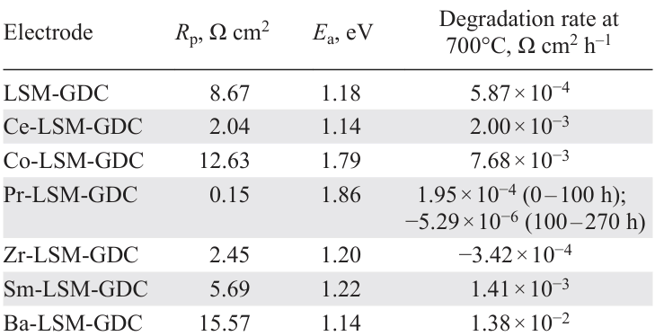
As a feature of the temporal behaviour of the Pr-modified electrode, it is worth noting that the highest degradation rate was observed in the first 10 h, followed by stabilization and a virtually constant Rp value up to 275 h. The application of the Pr-infiltrated cathode in the anode-supported tubular cell with the YSZ electrolyte of 10 µm in thickness allowed to obtain the superior current density of about 1.3 A cm–2 at 800°C and 0.7 V (using a fuel mixture of 50% H2/50% H2O) compared to the similar microtubular cells with the conventional LSM-YSZ (0.525 A cm–2 (Ref. 215)), Mn-infiltrated LSM-YSZ (0.7 A cm–2 (Ref.[222] )), 22 vol.% and 35 vol.% LSM-infiltrated YSZ (0.875 and 0.995 A cm–2, respectively[215]), and SDC/LSM infiltrated YSZ (0.842 A cm–2 (Ref. [334])).
In 2024, Kim et al.[322] investigated the influence of the concentration of the Pr nitrate water solution infiltrated into the conventional LSCF cathode on the performance of the YSZ electrolyte-supported cell (200 µm). Polyvinylpyrrolidone and glycine were added to the solution as a surfactant and a complexing agent, respectively. It was found that the use of 0.1M Pr6O11 precursor (0.8 at.% Pr loading according to the SEM study) increased the performance by 16.3%, while the infiltration of a higher concentration of 1M Pr6O11 precursor (12.4 at.% Pr loading) resulted in a 37.2% improvement.
Ge et al.[320] used an urea-assisted infiltration of PrOx to enhance the activity of LSM, LSCF and LSC electrodes. For the infiltration, urea was added to 1M Pr nitrate water/ethanol solution at a molar ratio of urea/cation equal to 10. Three infiltration cycles were performed followed by thermal treatment at 80°C for 2 h. Finally, the infiltrated samples were sintered in situ at 800°C for 1 h during the initial step of the cell operation. The fp values of 10, 2 and 4 were obtained for Rp of the infiltrated LSM, LSCF and LSC electrodes at 600 – 800°C. The PPD values obtained for the anode-supported cells with 15 µm thick YSZ electrolyte, 3 µm thick GDC buffer layer and with the infiltrated LSM, LSCF and LSC cathodes at 600°C were improved by 592, 122 and 90%, respectively. Caizán-Juanarena et al.[321] proposed a one-step effective infiltration of PrOx into GDC, LSM-GDC and LSM backbones through the spray-pyrolysis deposition.
Gu et al.[329] used activation with PrOx on both anode and cathode sides in symmetrical cells with YSZ/GDC electrolyte and PrBaMn2O5 + δ (PBMO) electrodes. The samples were infiltrated with 1M Pr nitrate aqueous solution (1 – 5 infiltration cycles, cell Nos 1 – 5, respectively), the sintering temperature in each cycle was 850°C. XRD analysis revealed the presence of PBMO of cubic structure and Pr6O11 in air, and PBMO tetragonal phase and PrO2 and Pr(OH)3 in the reduced samples. When the sample was re-oxidized in air at 800°C, only Pr6O11 and layered PBMO phases were observed. To evaluate the effect of the catalyst content on the electrode performance, the cells, obtained at varying number of infiltration cycles, were measured in hydrogen and air at 800°C. As shown in Fig. 13c, the ASR values dramatically reduced for all the infiltrated cells. The optimal Rp was observed for cell No. 3 equal to 0.20 Ω cm2 in H2 and 0.016 Ω cm2 in air at 800°C, demonstrating fp of 2 and 15, respectively. The PPD values of the electrolyte-supported cell with Pr-PBMO electrode reached 0.423 W cm–2 (170% improvement over the reference cell) in hydrogen and 0.227 W cm–2 in CH4 (70% improvement).
5.2. Enhancement of various catalyst impact on the electrode performance through the simultaneous impregnation with PrOx
Simultaneous infiltration of various catalysts with PrOx may be utilized for further improvement of the performance of various infiltrated electrodes even at low catalyst loading. For example, Javed et al.[330] investigated the influence of the catalyst nature on the performance of the MP-SOFC cathode. The authors compared two approaches to modifying the porous ScSZ backbone of the cathode: infiltration with a separate Nd0.6Sr0.4CoO3 – δ (NSC) catalyst and sequential infiltration with two catalysts, PrOₓ and NSC. Cells were infiltrated in three cycles to achieve an infiltrate loading of only 5 wt.%. After the first infiltration, the cell was heated to 800°C to achieve a good electronic network, while the subsequent infiltrations were followed by heating at 600°C to form smaller particles with a high surface area for TPB expansion. To prepare the composite electrodes, PrOx was infiltrated first, followed by infiltration with the NSC solution. The Rp values at 700/600°C were 0.1/0.37 Ω cm2 for NSC and 0.05/0.09 Ω cm2 for NSC-PrOx infiltrated cells. DRT analysis of the obtained spectra demonstrated that PrOx infiltration mainly enhances the electrode processes related to the surface exchange processes, such as oxygen dissociative adsorption/desorption, compared to the charge transfer processes. Moreover, the NSC-PrOx infiltrated cell had a lower activation energy (Ea) than the NSC infiltrated cell making the Pr-containing electrode more attractive for low-temperature applications. The PPD of the cell with the NSC-PrOx-ScSZ nanocomposite cathode reached 0.329 W cm–2 at 700°C, which is almost two times higher than that of the single cell without PrOx .
Research group led by M. Tacker[158] from the Lawrence Berkeley National Laboratory in the University of California, USA provided a comparative data on the infiltrated electrodes with variety of compositions for symmetrical MS-SOFCs consisting of a dense ScSZ electrolyte (7 and 12 µm) and porous ceramic ScSZ backbones (electrodes) (25 µm) sandwiched between porous stainless-steel metal supports. Several categories of cathode catalysts were infiltrated into the ScSZ cathode backbones, including perovskites with predominantly electronic conductivity, such as LSM, LSF, and LNF; MIEC perovskites LSCF, LSC, SSC; RP phases: Ln2NiO4 + δ (Ln = La, Nd, Pr); praseodymium oxide (PrOx); binary composites: LSM-SDC, PrOx-SDC, and SSC-SDC; ternary composites: LSM-SDC-PrOx and SSC-SDC-PrOx . The water-based metal nitrate solution with the addition of Triton-X 100 surfactant was used for the infiltration. The cathodes were infiltrated in three cycles, with intermediate firing at 850, 600, and 600°C. The anodes were infiltrated with SDC-Ni corresponding nitrates in four infiltration cycles with firing at 850, 600, 600, and 600°C.
For better comparison, the results of testing at 700°С of the cells with infiltrated single-phase catalysts along with electrical properties of the catalytic materials, as well as the data for the composite electrodes are summarized in Table 2[335-339] . Results for Pr2NiO4 + δ have been excluded from consideration as falling out of the overall picture, because of non-optimized sintering conditions.
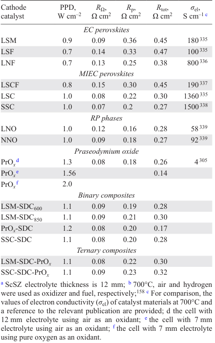
The cells with cathodes impregnated with SSC and LSC, which have superior electronic conductivity, exhibited the highest peak power among the perovskite materials (1 W cm–2 at 700°C), while the cells activated with LSM, LSF, LNF, and LSCF showed moderate performances of ~ 0.8 W cm–2 (Ref.[158]). SSC and LSC provided the lowest ohmic resistance RΩ , which may be attributed to higher ionic and/or electronic conduction of the catalyst, but may also indicate better infiltrate distribution in the electrode. In all cases, the total cell resistance was dominated by the polarization resistance, which was generally lower for the MIEC perovskites. The fast oxygen-ion transport characteristic of the layered RP phases (LNO, NNO) resulted in lower Rp values compared to those of perovskites and were approximately at the same level as those obtained for the composite materials containing an ionic conductor. This was the reason for the sufficiently high PPD values obtained for the RP and composite electrodes, despite the reduced electronic conductivity, as compared to perovskites. The highest PPD values were obtained for the cells with PrOx catalyst infiltrated as the first layer: PrOx (1.3 W cm–2) and SDC-PrOx (1.2 W cm–2) due to the superior oxygen transport properties of this catalyst. The rest of the cells with various binary and ternary composites demonstrated similar the PPD values of 1.1 W cm–2, and close RΩ and Rp values (0.8 – 0.9 and 0.28 – 0.32 Ω cm2). However, it should be noted that LSM-SDC composites, despite different sintering temperatures of the SDC infiltrate introduced as the first layer (600 or 850°C), provided approximately similar 38% increase in PPD when compared to LSM. Further optimization of the PrOx infiltrated cell by reducing the electrolyte thickness down to 7 µm allowed to obtain the PPD values of 1.56 and 2.85 W cm–2 at 700 and 800°C, respectively. The cell performance of 2 W cm–2 at 700°C was obtained using pure oxygen as an oxidant.
6. Infiltration of air electrodes with electron and mix-conducting backbones for SOCs with ZrO2-based electrolyte membranes
This Section briefly summarizes the studies on the infiltration of the electrodes with EC or MIEC backbones formed directly on ZrO2-based electrolyte membranes or on doped ceria buffer interlayers.[143][240][246][340-351] Pioneering study concerning infiltration of SOFC electrodes were presented by Watanabe and Uchida.[86][87] The authors improved the performance of LSM and LSC cathodes by infiltrating [Pt(NH3)4]Cl2 solution in 2-propanol/water mixture. For example, at a comparatively low Pt loading (0.1 mg cm–2), the current density of 0.6 A cm–2 was obtained for Pt-LSC electrode at η = −0.05 V at 800°C, which was 1.7 times higher than that without Pt catalysts. A large depolarizing effect was also observed with a Pt catalyzed LSM cathode, especially at high current densities. Silver was also considered as a good candidate for cathode infiltration in SOFCs operating below 800°C because of its excellent catalytic activity, high electrical conductivity and relatively low cost. Sakito et al.[352] infiltrated LSCF electrodes on anode-supported cells with YSZ electrolyte with Ag nitrate solution with hydroxypolycarboxylic acid (citric acid + glycine) in ethylene glycol. The infiltration of about 18 wt.% Ag fine particles into LSCF resulted in the PPD enhancement of the anode-supported cell with the YSZ electrolyte and GDC buffer layer (15/7 μm) from 0.16 to 0.25 W cm–2 at 630°C.
Electron-conducting backbones provide high electronic conductivity, and, in the case of MIEC electrode materials, sufficient electrocatalytic activity as well. Infiltration with an ion-conducting phase in this case results in an extension of the TPB density, thus increasing the surface area for the oxygen reduction reaction. The TPB length was shown to increase with increasing the electrolyte loading up to the percolation limit, which depends on both the particle size of the electrode backbone and the impregnated catalysts.[353][354] Jiang and Wang[343] investigated the influence of the GDC loading on the porosity and performance of the impregnated LSM electrode, which was formed on the YSZ electrolyte by screen printing, followed by sintering at 1100°C. The initial porosity of the LSM electrode decreased as 37.2% → 34.1% → 22.6% → 12% → 0% with increasing loading (vol.%) as 0 → 3.1 → 14.6 → 27.2 → 37.2. At 700°C, the Rp of the blank LSM electrode was 72.8 Ω cm2 and decreased to 11.7 Ω cm2 after cathodic polarization. Despite the reduced porosity, the lowest Rp among the infiltrated electrodes (0.21 Ω cm2) was observed at 37.2 vol.% loading (5.8 mg cm−2). The effect of the GDC infiltration was more pronounced on the low-frequency electrode process related to the dissociation and diffusion of oxygen on the LSM electrode surface. Wang et al.[341] demonstrated that the introduction of electrolytes significantly shortened the re-equilibration time and significantly promoted by the surface exchange kinetics. The authors showed that the surface exchange coefficient increased from 9.00 × 10⁻⁵ cm s−1 for the blank LSM electrode to 2.45 × 10⁻⁴ cm s−1 for the LSM electrode coated with YSZ and further increased to 7.92 × 10⁻⁴ cm s−1 for the SDC coated LSM.
Chen et al.[342][355] established 36 wt.% SDC infiltrated into the LSM backbone as the optimal. For the 42 wt.% infiltrated electrodes, a decrease in the cell performance at high current densities was caused by reduced porosity. Brito et al.[356] developed high-performance oxygen electrodes for reversible solid oxide cells. LSCF-SDC composite backbones were infiltrated with SDC nanoparticles. It was found that the amount of SDC from 10 to 20 vol.% did not greatly affect the morphology or size of the SDC nanoparticles. At 30 vol.% loading, SDC nanoparticles commenced agglomeration. Nevertheless, the average porosity of 30 vol.% SDC|LSCF-SDC was calculated to be 49%, which was sufficient for excellent gas diffusion. The SDC-infiltrated electrodes showed stable performance under anodic oxygen evolution operation at 0.5 A cm−2 at 750°C for 400 h.
Jiang et al.[340] observed separate infiltrated nanoparticles (~ 100 nm) at 20 wt.% Y-doped Bi2O3 (YDB) loading into the porous LSM backbone (average particle size 1 µm), while a continuous layer was formed at ≥ 40 wt.% YDB. Despite the denser electrode structure at high loading, the lowest Rp was observed at 50 wt.% loading (0.14 Ω cm2 at 700°C). Increasing the YDB loading increased the TPB length, providing more pathways for O2− incorporation and thus reducing high-frequency polarization resistance. The improved catalytic activity may be a result of the ‘spillover’ effect, since YDB is characterized by a higher surface exchange rate than YSZ. A similar loading level was found to be optimal[347] for the Er-doped Bi2O3 (EDB)-infiltrated LSM electrode with Rp equal to 0.22 Ω cm2 at 700°C on a ScSZ electrolyte.
Interestingly, relatively cheap materials that are also not noticeably conductive, such as CaO or BaCO3 can also be effective synergetic catalysts for ORR, being infiltrated in a small amount to LSCF-based electrodes (or other MIEC or composite electrode).[357][358] For example, BaCO3 infiltrated in amount of 9.2 wt.% into LSCF cathode not only increased the performance of the anode-supported cell with YSZ/SDC electrolyte from 0.66 to 0.73 W cm−2 at 700°C but also enhanced its stability in the 350 hour-test. Similar PPD enhancement from 0.71 to 0.8 W cm−2 was observed for 7.6 wt.% BaCO3 infiltrated LSCF-SDC electrode. Since BaCO3 can neither extend the reaction site nor offer additional oxygen ion vacancies because it is not an ionic conductor, the performance improvement was supposed to be caused by the synergistic catalytic activity of BaCO3 particles. It was found that BaCO3 helps to increase the surface exchange coefficient by a factor of about 10. At 700°C, Kchem for the blank LSF was 1 × 10⁻⁵ cm s−1, and it increased to 9.9 × 10⁻⁵ cm s−1 for LSF with BaCO3.
Infiltration of MIECs is a widely used practical method to improve the electrochemical performance of LSM oxygen electrodes. Infiltration with BSCF,[348] which has higher ionic conductivity and superior oxygen diffusion properties compared to LSM, was shown to improve the electrocatalytic activity of the BSCF-LSM nanocomposite electrode for ORR. However, the promotion factor value was significantly lower ( fp = 12) compared to that obtained for LSM impregnated with GDC ( fp = 56). A high promotion factor value ( fp = 78) was obtained at low temperatures for Pd-infiltrated conventional LSM/YSZ composite cathodes at low temperatures.[346] Pd nanoparticles were found to not only provide large electrochemically active sites, but also significantly promote the electrocatalytic activity of LSM-YSZ composite cathodes for ORR by facilitating the dissociation, diffusion, and exchange of oxygen species on the electrode surface, similar to that observed for the Pd-impregnated YSZ cathode.[359]
Wu et al.[356] enhanced the performance of the LSM air electrodes for reversible SOFCs with alternately infiltrated Sm0.5Sr0.5CoO3 – δ and Sm0.2Ce0.8O1.9 nanoparticles. Since the SSC was infiltrated first and then the SDC solution, the SDC nanoparticles had a significant inhibitory effect on the growth and coalescence of the SSC particles during sintering. In contrast, when the SDC was infiltrated first followed by the SSC solution, the sintering growth of the SSC particles was not suppressed, and larger SSC particles with a flocculent structure still existed in the LSM pores. The Rp values of the SSC-LSM electrode were apparently lower than those of the SDC-LSM, which was mainly due to the better oxygen adsorption and dissociation ability of Co-containing catalyst. Double infiltration further decreased Rp, but it was higher for the composite first infiltrated with SSC particles. The effect of the infiltration sequence on the electrode performance decreased with the number of infiltration cycles. The Rp values of the SDC-SSC-LSM electrodes with 1, 2, and 3 infiltration cycles were 0.5, 0.15, and 0.08 Ω cm2, respectively. The anode-supported cell with the YSZ electrolyte and SDC-SSC-LSM air electrode achieved PPD of 1.205 W cm–2 in the SOFC mode at 800°C, which was 8.73 times higher than that of the cell with the non-activated LSM electrode. The current density achieved 1.62 A cm–2 under 1.5 V in a SOEC mode, and the H2 generation rate was 3.47 times higher than that for the cell with the non-activated LSM electrode. Analysis of the spectra obtained under open circuit voltage conditions revealed that the high-frequency and mid-frequency polarization resistances were significantly decreased by alternating infiltration, indicating that the SSC and SDC nanoparticles significantly enhanced both the charge transfer and ion migration ability of the LSM electrode. The cathodic polarization potential of the SDC-SSC-LSM electrode remained stable during the test at the current density of ± 0.5 A cm–2 at 750°C, while the anodic polarization voltage first decreased and then slightly increased after 11 polarization cycles (44 h).
Exceptional electrode and cell performances were obtained by Park et al.[143] when SSC was infiltrated into the LSCF-SDC and LSC backbones using modified urea-glycine-assisted method. Two types of the commercial anode-supported cells were tested in the study: A-cell with a YSZ/GDC (7/3 μm) electrolyte and an LSCF-GDC/LSCF air electrode and B-cell with a YSZ/GDC (3/2 µm) electrolyte and an LSC air electrode. The developed technique was used to activate air electrodes. The SSC infiltration doubled the performance of the A-cell, reaching PPD of 0.8 W cm–2 at 650°C with a simultaneous decrease in Rp from 2.01 to 1.06 Ω cm2. The SSC infiltration applied to the B-cell allowed to obtain 1.4 W cm–2 and 0.67 Ω cm2. The large area A-cell (144 cm2) infiltrated with SSC nanocatalysts exhibited very stable behaviour at the cell voltage of ~1.25 V during constant current operation under 0.95 A cm–2 at 700°C for 200 h.
Hong et al.[354][355] studied the effect of the SSC infiltration to the LSCF cathode on its performance in the anode-supported SOFC with a 2.5 μm thick YSZ electrolyte and a GDC buffer layer (11.3 µm). The LSCF cathode (10.4 µm) was screen-printed over the buffer layer and sintered at 1100°C. The SSC infiltration was performed in a single infiltration step according to the sol-gel procedure described in Section 4.3.[292] The impedance spectra for reference and infiltrated electrodes were measured under a variety of thermodynamic conditions and comprehensively analyzed using a MIEC transmission line model (TLM). It was confirmed that infiltration decreased both the surface reaction resistance Rp (by ~ one order of magnitude) and the oxygen ion diffusion resistance Rs due to more diffusion paths and a wider TPB. After infiltration, the rate-determining step of surface reactions changed from the reduction reaction of the intermediate step of the electrode reaction to the dissociative adsorption reaction of the initial reaction step. It was concluded that the monodispersed SSC nanocatalyst enhances the electrocatalytic activity of ORR at the surface and contributes to the charge transfer through the surface rather than the bulk.
Zhao et al.[349] proposed the infiltration of the stable and active A-site deficient LNF over LSCF cathode (from 4.2 to 15.4 wt.% loading) to improve its long-term tolerance to CO2 and Cr poisoning. The electrode with 15.4 wt.% loading demonstrated the lowest Rp of 0.041 Ω cm2 at 800°C. The formation of numerous heterogeneous interfaces significantly improved the electron conduction and enhanced the dissociation of oxygen molecules, as evidenced by the energy band alignment of LSCF and LNF. The anode-supported single cell with the YSZ/GDC electrolyte and the LNF-LSCF infiltrated cathode achieved PPD of 1.08 W cm–2 at 800°C compared to 0.42 W cm–2 of the reference cell.
Chen et al.[360] presented an effective strategy to enhance LSCF tolerance to poisoning by infiltrating a hybrid catalyst composed of perovskite PrNi0.5Mn0.5O3 and exsolved PrOx nanoparticles. When subjected to an accelerated Cr poisoning test (direct contact with the Cr-containing alloy), the cells with a hybrid catalyst-coated LSCF cathode showed a superior PPD of 0.71 W cm–2 and a degradation rate of 0.04%/h at 0.7 V compared to those of the reference cell (~ 0.46 W cm–2 and a degradation rate of 0.4%/h at 0.7 V).
The dependencies of polarization resistance on catalyst loading of aforementioned cathodes, such as GDC-LSM,[343] YDB-LSM,[340] EDB-LSM,[347] LNF-LSCF,[349] BaCO3-LSCF,[357] as well as LSM-YSZ,[215] LSCF-YSZ,[271] LSFSc-YSZ[277] and PrOx-LSM-ScSZ [361] at T = 750°C, are shown in Fig. 14. As seen in the experimental data presented in the figure, the optimal level of catalyst loading aligns correctly with recommendations of Kiebach et al.[99] As it was mentioned in Section 4.5, the optimal amount of electrocatalyst to introduce into the backbone is ~ 30 wt.%, which is sufficient to build the effective TPB lengths.[296] For electrodes obtained through the MIEC catalyst infiltration (LSFSc, LSCF) into YSZ, the optimal loading level ranges 20 – 30 wt.%. This is due to the rising microstructural issues and, as a result, gas phase limitations with higher loading. Nevertheless, for electrodes produced by infiltrating ion-conducting catalysts into EC backbones, loadings up to 40−50 wt.% may be required to balance ionic and electronic conductivities. For electrodes activated by PrOx infiltration, the optimal catalyst loading level is below 10 wt.%, as further increasing the catalyst content not only reduces the electrodes’ porosity, but also affects the contact resistance.[328] Infiltration of various catalysts (both conducting and neutral) to MIEC backbones has also demonstrated higher efficiency at lower loading.
![[{"id":"KLZeddxKxk","type":"paragraph","data":{"text":"Dependencies of cathode polarization resistance on catalyst loading into corresponding backbones: PrO<sub>x</sub>-LSM-ScSZ,<sup>361 </sup>LSFSc-YSZ,<sup>277 </sup>LSCF-YSZ,<sup>271 </sup>LSM-YSZ,<sup>215 </sup>GDC-LSM,<sup>343 </sup>YDB-LSM,<sup>340 </sup>EDB-LSM,<sup>347 </sup>LNF-LSCF,<sup>349 </sup>BaCO<sub>3</sub>-LSCF <sup>357 </sup>at T = 750°C. Copy right belongs to Russ. Chem. Rev., 94 (11), RCR5186 (2025)."}}]](/storage/images/resized/fQDfOocr605k65zR3QWV0iHHK3hA4OBLtzL3X0J6_xl.webp)
When infiltrating a MIEC catalyst into an electrolyte baсkbone of doped ceria (usually formed on the buffer layer in SOCs with a YSZ electrolyte), the optimum can also be achieved in the range of 20 – 30 wt.% of the catalyst loading. For instance, Zhi et al.[362] improved performance of monolithic nanofiber LSCF electrode (75% porosity) by infiltrating 20 wt.% of GDC using related nitrate solution in N,N-dimethylformamide with 6 wt.% polyacrylonitrile. At 750°C, the power density of 1.07 W cm–2 was obtained for the anode-supported cell with 10 μm thick YSZ electrolyte and 7 μm thick GDC buffer layer and GDC-LSCF electrode, which was about 19% greater than that of the cell with the blank nanofiber LSCF.
La0.8Sr0.2Co0.8Ni0.2O3 – δ (LSCN) has been reported as a promising alternative cathode material for SOFCs with high electrocatalytic activity. Tan et al.[351] successfully applied this material for infiltration into the GDC buffer layer and Zheng et al.[350] used it with the LSM-SDC composite electrode. In the above works, thin-film YSZ electrolyte-supported anode cells were developed for high-efficiency steam and H2O/CO2 electrolysis, respectively.
Ai et al.[363] utilized infiltration technique to enhance catalytic properties of conventional Pt electrodes for SOFC with YSZ electrolytes using precursors such as CeO2 and GDC[364] and La0.8Sr0.2CoxMn1 – xO3 – δ (LSCM, x = 0, 0.5, and 1). For ORR under open circuit and at low current region, the promotion effect of both infiltrated CeO2 and GDC nanoparticles is almost the same, with Rp at 800°C for the infiltrated electrode equal to 0.92 and 0.78 Ω cm2 ( fp was 0.22 and 2.26 compared to pure Pt electrode), respectively. Under higher currents, the Pt electrode infiltrated with GDC exhibited much higher electrocatalytic activity. Under cathodic overpotentials of 50 mV, Rp of CeO2 – Pt changed to 1.10 Ω cm2 but in this case, the promotion factor fp also increased to 24.3 due to the high polarization of the reference Pt electrode under these conditions. For GDC-Pt at the same overvoltage, the increase in polarization resistance was significantly lower, to 0.81 Ω cm2, with fp = 33. It was suggested that lowering the partial pressure of oxygen with increasing polarization potential induced the partial reduction of ceria-based oxides, leading to an increase in the electronic and ionic conductivities, adding extra catalytic effect to facilitate ORR on the Pt electrode. No enhancement was observed under open circuit conditions, for the infiltrated LSC-Pt, LSCM-Pt and LSM-Pt electrodes, while at 100 mV, Rp values of 0.85, 1.71 and 4.37 Ω cm2 were obtained, respectively with corresponding fp equal to 35, 18 and 7. Greater enhancement for the LSC infiltrated electrode was explained its MIEC properties.
Several attempts were made to increase performance of full SOFCs based on commercial anode-supported half cells with YSZ or SSZ thin-film electrolyte and a GDC (SDC) cathode buffer layer.[365-368] For example, Zheng et al.[365] prepared a highly efficient and robust cathode with LSC-GDC functional layer by infiltrating a GDC scaffold formed on a GDC buffer layer (Tsint = 1200°C), with LSC nitrate solution with following thermal treatment at 800°C. Collector LSCF layer was then screen-printed and sintered at 1100°C. Infiltrated SOFC delivered PPD 1.2 W cm–2 at 750°C, which was 40% higher than that of the cell with a conventional GDC-LSC composite cathode, and an excellent long-term stability with a voltage degradation rate of 0.058%/100 h at 0.5 A cm–2 for 550 h. The DRT analysis of the infiltrated and conventional cells showed that infiltration fastened oxygen diffusion processes and accelerated chemical surface exchange of O2 and O2− bulk diffusion due to higher porosity and extended cathodic TPBs. It was observed that an electrode input associated with ORR process was dominant in the traditional cell, while in the infiltrated cell, the process related to H2 electrochemical oxidation becomes the rate-determining one.
Finally, it should be noted that infiltration of various air electrodes with PrOx catalyst is the most widely used method to increase performance commercial and non-commercial cells with ZrO2-based membranes.[111][314][321][323][369] For instance, Park and Barnett[369] obtained exceptional performance of the anode-supported cell with YSZ/GDC electrolyte (2.5 µm) and PrOx infiltrated LSCF-SDC cathode of 0.95 W cm–2 at 650°C. Osinkin et al.[111] observed gradual increase in PPD of the anode-supported cell with functionally graded anode and Zr0.84Sc0.16O1.92 electrolyte (30 µm) upon infiltrating cathode and anode with PrOx and CeO2 , respectively, from 0.4 W cm–2 to 1 W cm–2 (only cathode) and to 2.4 W cm–2 (both electrodes) at 900°C.
7. Comparison of the efficiency of the electrodes with various backbones
The following tables summarize the performance of SOCs with infiltrated air electrodes formed on a stabilized zirconia electrolyte backbone with a doped ceria buffer layer (Table 3,Table 4,Table 5)[370][371]; and on EC, MIEC, and composite backbones (Table 6)[372][373]. The tables also present data on the optimal loading level if the authors considered the dependence of cell performance on loading. For the electrolyte backbone, this level is rather high, typically amounting to 35 – 40 wt.%. However, this value is still lower than that for the conventional composites. To attain such high values, an ordinary infiltration protocol requires 20 – 30 cycles. However, the number of cycles can be substantially reduced using a concentrated nitrate solution or molten salts, and by adding ethanol, various surfactants and complexing agents. The use of backbones with structured porosity, obtained via innovative methods, allows for the introduction of approximately 25 wt.% of catalyst per cycle. At the same time, for ceramic bases with an open porosity of 55 – 65%, the loading level is 5 – 10 wt.% per cycle, further decreasing with an increase in the number of infiltrations performed.
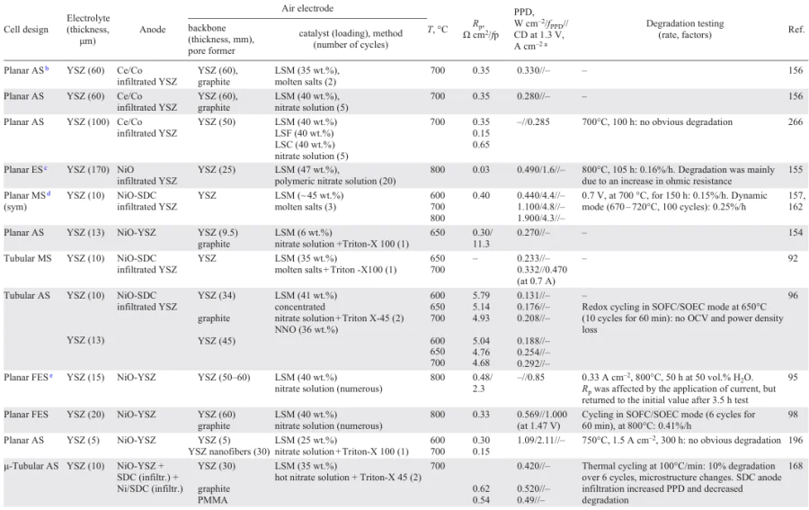
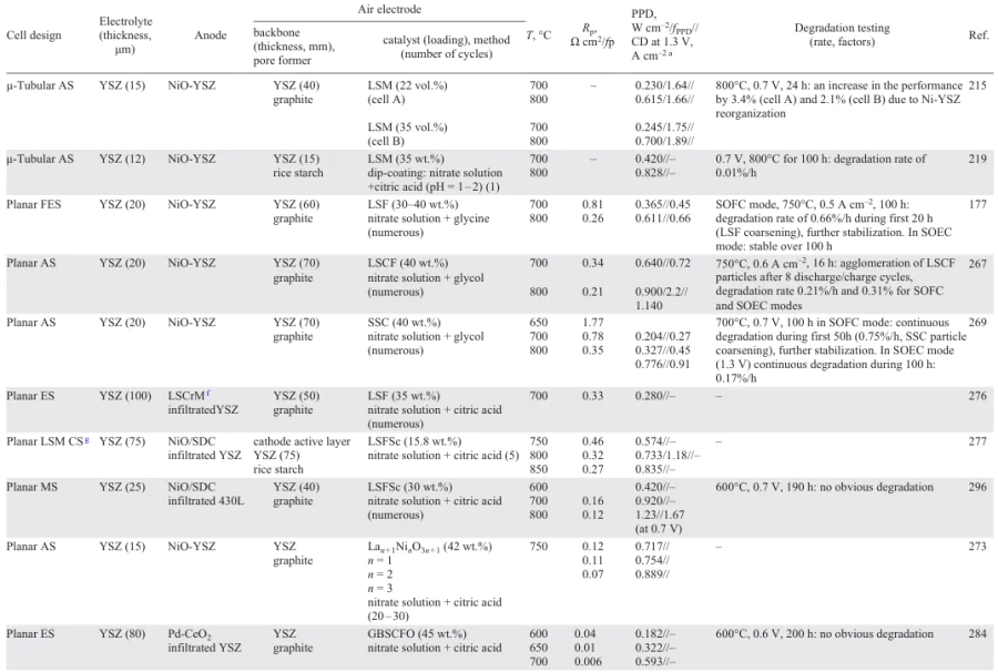
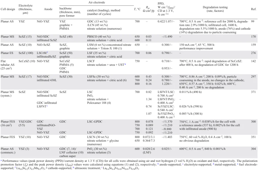
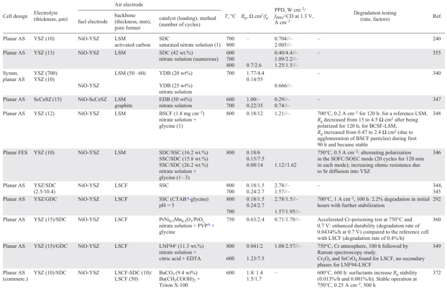

Along with the polarization resistance values, the promotion factor values, fp , are cited (Eq. 1). The highest fp values were obtained for the EC backbone (LSM) infiltrated with ionic conductors (up to 55) and MIECs (up to 12).
However, this factor cannot be used for electrodes with electrolyte backbones. In this case, we used the fPPD factor to compare the performance of cells with conventional composite electrodes to those obtained by infiltration.[370]
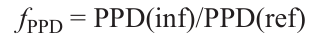
where PPD(ref) and PPD(inf) are the peak power densities of the reference cell with a baseline conventional composite electrode and the cell with a nanocomposite electrode obtained by infiltration, respectively.
Additionally, the tables comprise information on long-term testing conditions and calculated degradation rates. Clearly, degradation is primarily caused by particle coarsening in both the anode and the cathode. However, anode degradation is typically the dominant factor.
For cells with infiltrated air electrodes, the most promising performance values at 600°C (~ 0.4 W cm–2) were obtained for the symmetrical metal-supported cells due to the decreased thickness of anode and cathode and excellent ability for current collection.
The available literature data on the air electrodes with various backbones (MIEC, EC, electrolyte, composite) is summarized in FIg. 15. The criteria used to evaluate the total efficiency of a given backbone type are as follows: adhesion to the electrolyte (CTE mismatch); the necessary catalyst loading level to attain the required performance at decreased temperatures; the necessity of a collector layer in the case of a low electronic conductivity of a nanocomposite; the necessity of a buffer layer (in cases of increased chemical interaction with the electrolyte during the electrode backbone sintering); and, finally, the commercial availability of the cells with a given backbone type.
![[{"id":"xjM7q7s1J5","type":"paragraph","data":{"text":"Comparative analysis of various backbones based on literature review"}}]](/storage/images/resized/n2VYSFNHPIqs8iuqeLhedhPaxiXEYUFq566kUygJ_xl.webp)
Analysis of the literature indicates that composite backbones are the optimal choice for SOCs. These backbones exhibit superior compatibility with ZrO2-based electrolytes compared to single-phase EC or MIEC materials. They also require lower catalyst loadings than electrolyte-based backbones. In addition, composite backbones offer greater flexibility in catalyst selection, as microstructural factors play a more critical role than catalyst conductivity (see Section 3). Moreover, these backbones are readily available in commercial SOCs. Therefore, infiltration of composite backbones enables significant enhancement of SOC performance at reduced costs. However, challenges related to chemical reactivity with ZrO2-based electrolytes persist, limiting the range of materials suitable for composite backbone fabrication.
Electrolyte-based backbones show promise for ZrO2-based devices, particularly with scalable commercial production of three-layered structures comprising a thin-film electrolyte and porous backbones for subsequent electrode infiltration. Symmetric metal-supported cells integrated with these three-layered structures represent the most promising configuration for advancing infiltration technology applications.
8. Scalable infiltration techniques
Infiltration is a simple, however, rather ‘intuitive’ technique for creating nanostructured surfaces for electrodes and catalysts. This is typically performed on a laboratory scale using microliter syringes, pipettes, or brushes. The process is inefficient and time-consuming, often leading to two main problems: first, non-uniform distribution of precursors in the porous backbone, and second, aggregation of nanoparticles in the case of high weight loading infiltrations. When considering the development of large-scale SOCs,[13][361][374-377] the above problems of the infiltration technology may become more pronounced.
Several research groups have proposed a low-cost ultrasonic spray infiltration process with easily controlled parameters which allowed a one-step infiltration with satisfactory loading and uniform particle distribution throughout the backbone volume. Song et al.[378] used the ultrasonic spray equipment for the SSC infiltration of the conventional composite LSCF-GDC air electrodes in the flat tubular anode-supported SOFCs with a bilayer ScCeSZ/GDC electrolyte. The ultrasonic spray equipment consisted of a syringe feeder and an ultrasonic spray nozzle capable of moving along the length and width of the sample to be infiltrated. Schematic and actual images of the ultrasonic spray infiltration equipment are shown in Fig. 16a.
![[{"id":"yx-yIVTSsD","type":"paragraph","data":{"text":"(<i>a</i>) A schematic and an actual image of the ultrasonic spray infiltration equipment.<sup>378 </sup>1 — frequency source, 2 — syringe pump, 3 — spray nozzle, 4 — x-axis motor, 5 — z-axis motor, 6 — air flow meter, 7 — nozzle movement controller, 8 — SOFC. Copyright belongs to the Royal Society of Chemistry; (<i>b</i>) a schematic of the ultrasonic spray technique with urea-assisted infiltration.<sup>142 </sup>Copyright belongs to Elsevier; (<i>c</i>) customized inkjet printing system used for the infiltration experiment (the insets show the 16-nozzle Domino valve-jet print head and the commercial anode-supported SOFC).<sup>379 </sup>Copyright belongs to MDPI; (<i>d</i>) a schematic and SEM image of MS-SOFCs with symmetrical architecture suitable for scale-up.<sup>183 </sup>Copyright belongs to Elsevier."}}]](/storage/images/resized/scruGcYmjMmBnJVjwLD5RTbVuApOscQwREB9yse1_xl.webp)
Dowd et al.[176] developed an automated one-step infiltration process for SOFC wet impregnation using a Sono-Tek® ultrasonic spray nozzle. The authors optimized the content of chelating agent (citric acid) and various surfactants (Triton™ X-100, sodium dodecylbenzene sulfonate, and sodium dodecyl sulfate) to increase the backbone wetting properties and to achieve a maximum catalyst loading (~ 10 wt.%) during one infiltration step. Uniform droplet distribution was achieved by continuous ultrasonic vibration along the length of the nozzle. After infiltration, the cells were then placed in a non-convection oven at 850°C for 2 hours to calcine the electrocatalyst (LSC, PSC) within the porous LSCF cathode structure.
Rehman et al.[142] proposed a simple scalable urea-assisted ultrasonic spray infiltration technique. Using urea as a precipitant, the intermediate calcination step after each infiltration cycle can be omitted, and the subsequent infiltration step can be performed after a drying step (at ≤ 100°C). The desired catalyst phase can be obtained after all infiltration steps through a single calcination step. In addition, it has been demonstrated that the low calcination temperature of the cathode (≤ 900°C) can help reduce the degradation of ZrO2-based SOFCs even in the absence of doped cerium dioxide buffer layers. The integration of an ultrasonic spray technique with urea-assisted infiltration allowed this process to be scaled up to any desired cathode area (Fig. 16b).
Tomov et al.[379-382] chose drop-on-demand inkjet printing as a single processing technique for the fabrication of thin electrolyte layers, buffer layers, electrode layers and for infiltration of catalysts into the electrode backbone. Fig. 16c shows a schematic of the inkjet printing process, utilized for prototyping of high-quality LSCF cathodes on an anode-supported SOFC stack using a commercial low-cost inkjet printer HP Deskjet 1010. A HP61 black ink cartridge, which fits the HP Deskjet 1010 model and provides a 600 × 300 dpi resolution, was cleaned with ethanol by using an ultrasonicator and filled with the prepared LSCF inks using syringes. Drop-on-demand inkjet printing allowed reproducible droplet dispensing in the range of pL to nL volumes at high rates (kHz), provided excellent control of thickness and uniformity and introduced the ability to print 2D and 3D patterns, as well as deliver precursors into porous backbones with high accuracy. It could be concluded that the above technology is cost effective and environmentally friendly by minimizing waste of expensive precious or rare-earth metal-based precursors.
Shim and co-workers[383-385] also used lLow-cost commercial inkjet printers for the fabrication of the porous SOFC cathode backbones and their subsequent infiltration. Tarancón and co-workers[386] carried out the infiltration of the ceria scaffolds placed on YSZ electrolyte using a customized printer with a commercial cartridge C6602A from Hewlett – Packard (Palo Alto, CA, USA) with a nozzle diameter of ~ 60 µm. The motion of the 3-axis system was controlled by Arduino[387] and the printing process was controlled by Processing©.[388] Charalampakis et al.[389] successfully implemented inkjet printing of LSM-YSZ thin films as cathode layers using water-based nanoparticle inks.
Dogdibedovic et al.[183] proposed a scalable infiltration technology for MS-SOFCs with a symmetrical architecture with an effective area of up to 50 cm2. The symmetrical structure provides exceptional mechanical strength and enables welded electrical connections on both sides of the cell. The electrolyte and symmetrical backbone layers were debinded in air at 525°C and sintered in 2% H2/98% Ar at 1350°C, followed by infiltration of catalyst precursors which are then converted to the final catalyst composition by firing in air (Fig. 16d ). Instead of standard molten salt infiltration route previously developed by this research group, the cells were impregnated with 3.5M (Pr) and 3.2M (Ce, Sm, Ni) aqueous nitrate solutions, which were sprayed or dripped onto the cell surface, followed by vacuum evacuation. Instead of the standard ‘slow’ firing procedure involving heating at a rate of 3°/min to 850°C (first cycle) and 600°C (subsequent cycles), a ‘fast’ firing procedure was proposed in which a furnace was preheated to 500°C and the cells were placed directly in the hot furnace for 10 min, then removed from the furnace and cooled naturally in air. This modification drastically reduced the infiltration time and allowed numerous infiltration cycles to be performed in a single shift. Very fast thermal processing and perfect cell flatness during debinding and sintering were enabled using the symmetrical MS-SOFC architecture.
Detailed description of scalable techniques for the formation thin-film ZrO2-based electrolyte membrane simultaneously with porous backbones on both anode and cathode side suitable for following infiltration can be found in the number of studies for both planar[197][275][300][390][391] and tubular cells.[57][183][392] However, today, for the successful development of technology, several challenges must be addressed. Firstly, the level of sufficient porosity must be established. Secondly, the proper pore formers must be found to create a net of pores with sufficient strength and excellent gas permeability. Thirdly, the impact of final porosity on infiltrated electrode conductivity, TPB length, electrochemical performance and durability must be clarified.
9. Conclusion
This review implements for the first time an electrolyte-centered approach to summarize the extensive information on developing infiltrated electrodes for solid-state ceramic cells with Y2O3- or Sc2O3-stabilized ZrO2 electrolyte membranes, which are most widely used in commercial devices. Several research groups have made significant contributions to this field; therefore, the most-cited studies (more 50 citations) are shown in FIg. 17.[393-397] Analysis of the citation numbers between 2004 – 2020 years and 2021 – 2025 years shows that infiltration is still among the top technologies for the electrode modification for YSZ-based SOFCs.
![[{"id":"bxtLZs-LXl","type":"paragraph","data":{"text":"The most cited articles concerning infiltration technology for air electrodes in ZrO<sub>2</sub> based cells in 2004 – 2020 and 2021 – 2025 based on the search (YSZ AND (INFILTRAT* OR IMPREGNAT*) AND SOFC*) in the Scopus database. Sholklapper et al.,<sup>145 </sup>Tucker et al. (2007),<sup>92 </sup>Zhi et al. (2012),<sup>362 </sup>Tucker et al. (2008),<sup>93 </sup>Huang et al. (2005),<sup>91 </sup>Huang et al. (2004),<sup>89 </sup>Bidrawn et al. (2008),<sup>150 </sup>Chen et al. (2008),<sup>270 </sup>Cable and Sofie,<sup>194 </sup>Zhi et al. (2011),<sup>195 </sup>Huang et al. (2006),<sup>156 </sup>Sakito et al.,<sup>352 </sup>Yamahara et al.,<sup>243 </sup>Tong et al.,<sup>300 </sup>Nicollet et al.,<sup>304 </sup>Liang et al. (2009),<sup>247 </sup>Choi et al. (2011),<sup>273 </sup>Park et al,<sup>369 </sup>Fan et al.,<sup>267 </sup>Liang et al. (2008),<sup>359 </sup>Zhu et al.,<sup>393 </sup>Choi et al. (2012),<sup>283 </sup>Jiang et al.,<sup>340 </sup>Lu et al.,<sup>174 </sup>Liang et al. (2008),<sup>246 </sup>Chen et al. (2010),<sup>272 </sup>Adijanto et al.,<sup>268 </sup>Küngas et al.,<sup>394 </sup>Chen et al. (2007),<sup>355 </sup>Chen et al. (2014),<sup>286 </sup>Ai et al.,<sup>348 </sup>Kim et al.,<sup>284 </sup>Laguna-Bercero et al.,<sup>281 </sup>Huang et al. (2006),<sup>395 </sup>Bidrawn et al. (2011),<sup>396 </sup>Kim-Lohsoontorn et al,<sup>397 </sup>Chen et al. (2015),<sup>285 </sup>Tucker (2017),<sup>182 </sup>Hong et al.<sup>357</sup>"}}]](/storage/images/resized/dJPoFvC6tESDay8Dmyy6DR3PqfXXWQDJRIpfCpQs_xl.webp)
In this review, we briefly consider the main principles of the infiltration process and controllable parameters at each step. The key advantages infiltration has over conventional electrode formation methods and those using specialized equipment are its simplicity and the ability to separate the formation of a microsized backbone and nanosized infiltrate.
The porous backbone can be formed on the electrolyte surface either after being sintered separately, or by being co-sintered with the supporting electrode (typically anode) being formed through the use of conventional, scalable ceramic methods such as tape casting, screen printing, and tape calendaring. Because of the broad choice of pore formers and the ability to use high sintering temperatures, backbones with excellent adhesion and mechanical strength, as well as sufficient porosity (55 – 60 vol.%) can readily be formed. Typically, the pore former content varies within the range of 20 – 30 wt.%, since high temperatures (usually above 1400°C) are used for their sintering. For electrode bases based on an electronic conductor and MIEC, the content of the pore former is lower (5 – 10 wt.%), and bases with natural porosity formed by reducing the electrode sintering temperature can be used. Using mixtures of fine, carbon-containing pore formers and acrylic ones with larger particles enables the formation of well-developed, continuous networks of pores. Advanced methods such as freeze casting, electrospinning, etc., can be applied to obtain backbones with a structure highly suitable for subsequent infiltration and to significantly reduce the number of infiltration cycles. The typical thickness of the SOC electrode backbone ranges from 20 to 30 µm to cover the electrochemically active zone. However, when an expensive catalyst is used for infiltration, such as praseodymium nitrate, the thickness can be decreased down to 10 µm or even lower.
Because the uniformity and particle size of the infiltrated catalyst particles directly impact not only the electrode and the cell’s PPD but also its long-term stability, special attention should be given to methods that allow for their regulation. In this sense, using diluted solutions (0.5 – 1 M) based on water/ethanol, surfactants (e.g., Triton X-100) and complexing agents (e.g., citric acid, urea) is very useful. Additionally, some advanced infiltration methods are reviewed that make the infiltration process more effective by reducing processing time and the number of cycles while also avoiding intermediate calcinations.
Infiltration enables the fabrication of nanocomposite electrodes using various state-of-the-art electrode materials and oxide promoters with excellent catalytic properties. These materials cannot be applied directly to the ZrO2-based electrolyte due to thermomechanical or chemical incompatibility. Furthermore, the amount of catalyst can be significantly reduced compared to conventional composite electrodes, making it cost-effective. Special attention is given to the combined infiltration of buffer material followed by the loading of a perovskite catalyst to increase cell performance and durability and prevent nanoparticle coarsening.
Finally, a brief overview of the infiltration of air electrodes with EC or MIEC backbones used in SOCs with ZrO2-based electrolyte membranes is provided. The promotion factors fp and fPPD were used to evaluate the effect of infiltration on polarization resistance and PPD compared to the values for the reference (base) samples. In our opinion, his approach gave a higher degree of precision in evaluating the results obtained by different research groups for electrodes with various backbones, infiltrate compositions, and infiltration techniques. However, the factor values cannot be considered the main criterion for choosing backbone/catalyst materials. Clearly, the values will be higher when using a reference (backbone) material with poor performance at decreased temperatures.
Throughout the review, we have discussed short and long-term stability issues as being the most prominent in nanoscale systems. Scalable infiltration methods were also briefly considered as a solid foundation for implementing this advanced technique on a large scale.
Section 7 summarizes the main results and discusses the effectiveness of using a certain type of backbone.
To conclude, it is important to note that valuable experience has been gained during more than 30 years of studying infiltrated air electrodes in contact with ZrO2 electrolytes (reported in approximately in 400 publications). The principles that had previously been developed can certainly be applied to novel ZrO2-based materials with advanced properties that have been developed recently, as well as to other types of electrolytes, taking into account their inherent features. The remarkable performance results that been achieved for fuel, electrolysis, and reversible cells with infiltrated electrodes in contact with conventional YSZ electrolyte membranes will encourage still further achievements through the use of advanced electrolytes. The authors hope that this review will be useful for the research and development groups dealing with YSZ or ScSZ based electrochemical devices as the source of valuable information on the cost-effective method to improve their performance.
10. List of abbreviations
ASR — area specific resistance,
BDC — Bi-doped ceria,
BET — Brunauer – Emmett – Teller,
BSCF — Ba0.5Sr0.5Co0.8Fe0.2O3 – δ ,
C — carbon black,
CMO — Co1.5Mn1.5O4,
CTAB — cetrimonium bromide,
CTE — coefficient of thermal expansion,
DRT — distribution of relaxation times,
EC — electron conductor,
EDB — Er-doped Bi2O3,
EDTA — ethylenediaminetetraacetic acid,
ERMINE — electrochemical reactions in microstructural networks,
G — graphite,
GBSCFO — GdBa0.5Sr0.5CoFeO5 + δ ,
GBSCO — GdBa0.5Sr0.5Co2O5 + δ ,
GDC — Gd-doped ceria,
GPDC — Gd, Pr co-doped ceria,
LbL — layer-by-layer,
LBSCO — LaBa0.5Sr0.5Co2O5 + δ ,
LCN — nickel-substituted lanthanum cobaltite,
LNC — cobalt-substituted lanthanum nickelate,
LNF — lanthanum nickelate ferrite,
LNO — layered lanthanum nickelate,
LSC — lanthanum strontium cobaltite,
LSCF — lanthanum strontium cobaltite ferrite,
LSCM — lanthanum strontium cobaltite manganite,
LSCN — lanthanum strontium cobaltite nickelate,
LSFSc — strontium scandium substituted lanthanum ferrite,
LSM — lanthanum strontium manganite,
LSF — lanthanum strontium ferrite,
MIECs — mixed ionic electronic conductors,
MS-SOECs — metal-supported solid oxide electrolysis cells,
MS-SOFCs — metal-supported solid oxide fuel cells,
NNO — layered neodymium nickelate,
NSC — neodymium strontium cobaltite,
OCV — open circuit voltage,
ORR — oxygen reduction reaction,
PBC — Pr0.5Ba0.5CoO3 – δ ,
PBCFO — PrBaCo2 – xFexO5 + δ ,
PBMO — PrBaMn2O5 + δ ,
PBSCO — PrBa0.5Sr0.5Co2O5 + δ ,
PDC — Pr-doped ceria,
PEMA — polyethyl methacrylate,
PMMA — polymethyl methacrylate,
PPD — peak power density,
PSC — Pr0.7Sr0.3CoO3 – δ ,
RP — Ruddlesden – Popper (phase),
Rp — polarization resistance,
SBSCO — SmBa0.5Sr0.5Co2O5 + δ ,
ScCeSZ — Sc0.10Ce0.01Zr0.89O2,
ScSZ — scandium stabilized zirconia,
SDC — Sm-doped ceria,
SEM — scanning electron microscopy,
SOEC — solid oxide electrolysis cell,
SOFC — solid oxide fuel cell,
SOC — solid oxide cell,
SSC — samarium strontium cobaltite,
STFC — strontium titanate ferrite cobaltite,
SYSZ — (Sc2O3)0.1(Y2O3)0.01(ZrO2)0.89 ,
TPB — triple phase boundary,
μT-SOFCs — microtubular solid oxide fuel cells,
U/C — urea/metal cations ratio,
YAZ — Y2O3 and Al2O3-doped zirconia,
YDB — Y-doped Bi2O3 ,
YSZ — Y2O3-stabilized zirconia,
XRD — X-ray diffraction.
Acknowledgements
This work was financially supported by Russian Science Foundation (Agreement No. 25-23-00168). The authors are grateful to Mr. Peter R. Orman, Victoria University of Wellington, BA English Language and Linguistics (Wellington, New Zealand) for his valuable help in proof-reading our manuscript.
References