
Keywords
Abstract
Mechanical recycling of high-density polyethylene (HDPE) is already being carried out on an industrial scale, while extrusion-based 3D printing still relies on a few polymers that are easier to print but clearly less sustainable. In the present review, we bring together the experimental literature of 2013–2026 on printing this polymer, following the whole chain from virgin resin or washed post-consumer waste to the finished part: melt rheology and the workable melt-flow-index window, crystallization kinetics as the origin of shrinkage and warpage, filament extrusion practice and quality control, validated printing windows and bed-adhesion strategies, and the mechanical performance of printed parts against injection-molded (IM) baselines. A number of studies report that, under optimized conditions, tensile strength and stiffness of the resulting products approach those of IM HDPE materials, although performance varies widely with grade, formulation, and print parameters; adequately stabilized recyclate has been shown to retain most of its mechanical performance over 3–5 processing cycles in the systems studied, which supports distributed recycling into filament. Original processing maps, schemes and comparative tables gather the scattered numerical windows into design guidance, while the barriers that remain, namely standardization, long-term durability data and equipment availability, are set out as research priorities.
The bibliography includes 130 references.
1. Introduction
1.1. Background and context
Global plastics production has grown almost without interruption since the 1950s, a decade ago, the cumulative amount of polymer manufactured worldwide was already put at some 8300 million tonnes.[1] Annual output stands today at around 414 million tonnes, and polyolefins take the largest share of it.[2] High-density polyethylene (HDPE) on its own represents roughly 12 – 13% of the total, being the standard material for bottles, caps, crates, drums, pipes, household articles and a wide range of agricultural containers.[1, 3] Of this volume, only a small part is recovered: according to Geyer et al.,[1] about 9% of all the plastic waste generated up to 2015 had been recycled, and even though European collection rates have improved considerably since then,[2] most polyethylene (PE) still ends up in landfill or incineration. For this reason, any technology able to convert collected HDPE into higher value-added products impacts on one of the largest single-use plastic streams of the plastics economy.[4, 5]
Additive manufacturing (AM) followed an entirely separate trajectory. Ngo et al.[6] describe how layer-by-layer fabrication moved on from rapid prototyping to functional components for aerospace, construction and biomedical applications, while Attaran[7] puts its industrial attractiveness down to tool-free production, short design iterations and the economics of small series. Among the seven AM process categories defined in ISO/ASTM 52 900,[8] material extrusion is by far the most widespread; its filament-fed variant, known as fused filament fabrication (FFF) or fused deposition modeling (FDM), dominates the desktop and the small-industrial segment.[9, 10] Ford and Despeisse[11] argue that AM can support sustainable production because it reduces material waste and shortens supply chains; several groups have taken the argument a step further, noting that if the printer feedstock is made from post-consumer plastic, distributed manufacturing and distributed recycling merge into one local loop.[5, 12, 13] In our previous review,[14] we examined the viability of 3D printing as a recycling route for polymers in general, and identified the polyolefins as the least developed branch of that field.
The material base of FFF has remained, perhaps surprisingly, narrow. Polylactic acid (PLA) and acrylonitrile-butadiene-styrene (ABS) still cover most of the consumption, together with glycol-modified poly(ethylene terephthalate) (PETG) and, in the professional segment, polyamides and high-temperature polymers such as polyetherimide and polyether-ether-ketone.[10, 15] Tanikella et al.[16] measured the tensile strength of the commercial filament palette and confirmed that materials available to users maps, almost exclusively, onto amorphous or slowly crystallizing polymers. PLA is stiff and easy to print, but it is brittle, thermally limited and, in practice, rarely recycled.[14, 17] ABS tolerates higher service temperatures, at the cost of styrene-containing volatiles during printing and a dependence on well-ventilated or enclosed machines.[4, 18] HDPE, on the contrary, is cheap, tough, chemically inert and already collected at scale in the existing recycling streams; as virgin resin it costs roughly €1 – 2 per kilogram, far less as washed post-consumer flake, against €15 – 30 per kilogram for boutique commercial filaments.[3, 4, 12] Why a material with these characteristics is hardly used in extrusion-based printing is the question from which the present review starts.
1.2. The current state of HDPE in 3D printing
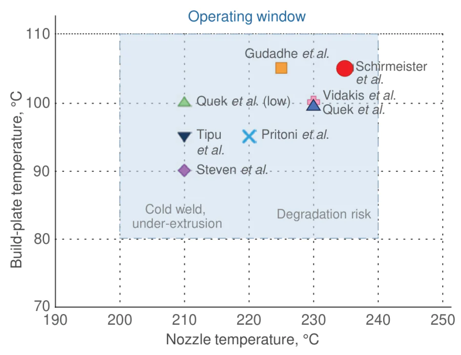
The reasons for this have been well documented; Schirmeister et al.[19] summarized them as massive shrinkage, warpage, void formation and poor adhesion, toward the common build plates as much as between the deposited strands. HDPE crystallizes to a degree of 60 – 80%, and the accompanying specific-volume contraction is several times higher than that of amorphous ABS or PLA, which remains largely amorphous under typical FFF cooling conditions.[3, 20] The latter polymers shrinkage is purely thermal, without a first order volume change on solidification, and residual stresses can build up only once the material cools below its glass transitions (105°C for ABS and 60°C for PLA). In HDPE, by contrast, crystallization causes a pronounced volume change already at 115 – 120°C. Measurements on printed polyolefins give coefficients of linear thermal expansion around 1.5 – 2.5 × 10\(^{-4}\) K\(^{-1}\), roughly twice those of the conventional FFF polymers.[21, 22] Each newly deposited layer is welded onto layers that have contracted already, so the accumulated residual stress is released as corner lifting, debonding or macroscopic distortion.[23, 24] There is also the non-polar HDPE surface, with a surface energy near 30 mN m\(^{-1}\), which wets neither glass nor the polyimide and adhesive-coated sheets that serve PLA so well,[3, 19] while the narrow crystallization window leaves no more than seconds for interlayer chain diffusion before the weld solidifies.[25, 26] Still, the past decade has given convincing demonstrations that none of these barriers is fundamental. Schirmeister et al.[19] printed HDPE whose tensile strength and modulus matched IM references, by combining polyolefin build plates, tuned nozzle temperatures and an extrusion-rate gradient that suppresses voids. Gudadhe et al.[24] turned waste-derived HDPE into a printable material with less than 0.5 wt.% of a sorbitol nucleating agent, about 10% linear low-density polyethylene (LLDPE) and a glued brim. Rigotti et al.[27] processed HDPE recovered from nautical waste, and Quek et al.[28] compared commercial and post-consumer recycled HDPE filament under identical printing conditions. Such reports, however, are scattered across journals of polymer science, manufacturing and waste management. Each one optimizes a particular grade, machine or additive package, and the numerical windows they establish were never collected in a single reference. The reviews that exist cover either recycled polymers in AM as a class[4, 5, 14, 18, 29] or PE material extrusion in the broad sense, including powder and pellet routes.[3] To our knowledge, no critical review of the last ten years is devoted specifically to HDPE in filament-based printing along the full chain from feedstock to printed part. The present review is intended to close that gap.
1.3. Scope, sources and objectives of the review
The experimental literature examined here was published, for the most part, between 2013 and 2026. Earlier sources appear only where the recent work builds on mechanisms they had established. As for the material scope, we consider HDPE- and HDPE-rich systems: virgin resin, post-consumer and post-industrial recyclate, HDPE blends with other polyolefins or polyethylene terephthalate (PET), and filled or fiber-reinforced HDPE composites. The process scope covers fused filament fabrication and the closely related screw-fed and pellet-fed material-extrusion platforms, plus the filament-extrusion step that comes before printing; powder-bed sintering of polyethylene and injection molding enter the discussion only as reference points.[6, 30] A literature search was conducted in the Scopus and supporting databases, using combinations of the terms ‘high-density polyethylene’ or HDPE with ‘fused filament fabrication’, ‘fused deposition modeling’, ‘material extrusion’ and ‘3D printing’, supplemented by the analysis of reference lists from the selected publications.
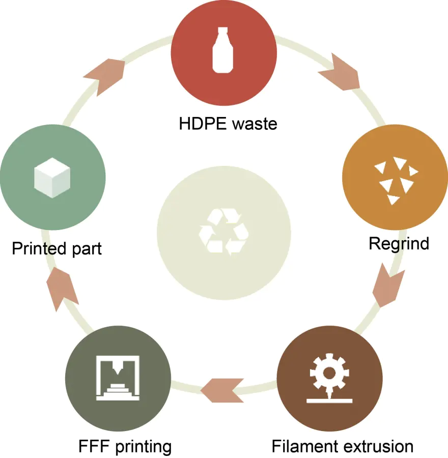
Within these boundaries, five questions are addressed. First, which properties of HDPE — specifically, its crystallization behavior, melt rheology and interfacial characteristics — control the response to the FFF process? Second, how to produce filament of adequate quality from virgin and recycled HDPE, and which extrusion variables matter most? Third, which printing windows and adhesion strategies have actually been validated in experiments, and to what extent warpage can be kept within acceptable limits? Fourth, what are the actual mechanical and physical performance of printed HDPE products compared with baseline IM samples, and how this performance changes with the incorporation of additives, fillers and blend partners? Fifth, how HDPE behaves over repeated recycling cycles, and what role it can play in distributed, closed material loops under the current European regulatory framework? Figure 1 shows the material chain around which the review is organized.
2. HDPE as a material for extrusion-based printing
2.1. Molecular architecture and crystallinity of the polyethylene grades
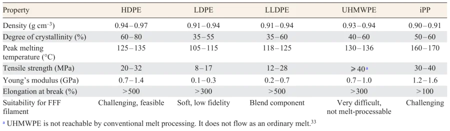
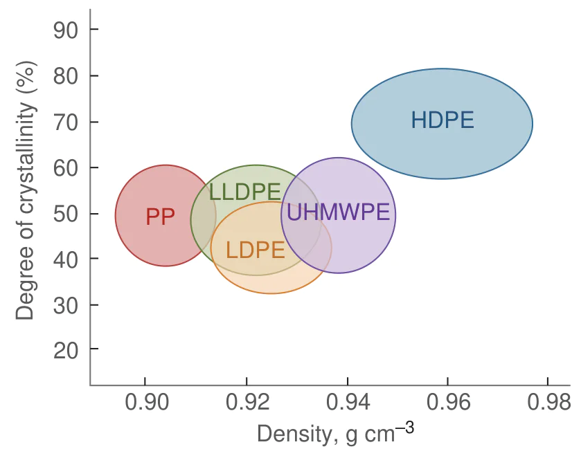
Polyethylene is not a single polymer but a family, whose members differ mainly in chain branching and molar mass; these two variables decide almost everything that matters inside a printer. HDPE consists of essentially linear chains with very few short branches. The chains pack into thick lamellar crystals; density rises this way to 0.94 – 0.97 g cm\(^{-3}\) and the degree of crystallinity to 60 – 80%, depending on grade and thermal history.[3, 20] Low-density polyethylene (LDPE) carries long-chain branches that disturb the packing and bring crystallinity down to roughly 35 – 55% at densities of 0.91 – 0.94 g cm\(^{-3}\); LLDPE reaches an intermediate order through controlled short-chain branching introduced by comonomers.[31, 32] Ultra-high-molecular-weight polyethylene (UHMWPE) lies at the upper extreme of the molar-mass scale, with weight average molar masses typically exceeding 3 × 10\(^6\) g mol\(^{-1}\); it does not flow as an ordinary melt and cannot be printed by conventional filament extrusion without profound modification, as Collins Rice et al.[33] discuss in their survey of UHMWPE processing strategies. Figure 2 places the main grades, together with isotactic polypropylene (iPP), on a density-crystallinity map, and Table 1 provides indicative property ranges relevant to FFF.
The crystallinity that gives HDPE its stiffness, chemical resistance and barrier performance is also direct origin of its poor printability. Melting stays confined to a narrow interval, with peak melting temperatures of about 125 – 135°C;[20, 34] a deposited strand therefore solidifies abruptly once it cools below the crystallization onset, and the crystallization step adds a large and sudden volume contraction on top of the ordinary thermal shrinkage of the cooling melt.[21, 22] An amorphous printing polymer spreads the same total contraction smoothly over a wide temperature range and, what matters more, stops contracting to any real extent once it vitrifies. The practical consequences of this difference, residual stress and warpage, run through Sections 4 and 5. On the positive side, the glass transition of PE lies far below room temperature; this is why printed HDPE parts stay ductile and tough at ambient conditions where PLA parts fracture in a brittle manner.[16, 17]
2.2. Melt rheology and the melt flow index window
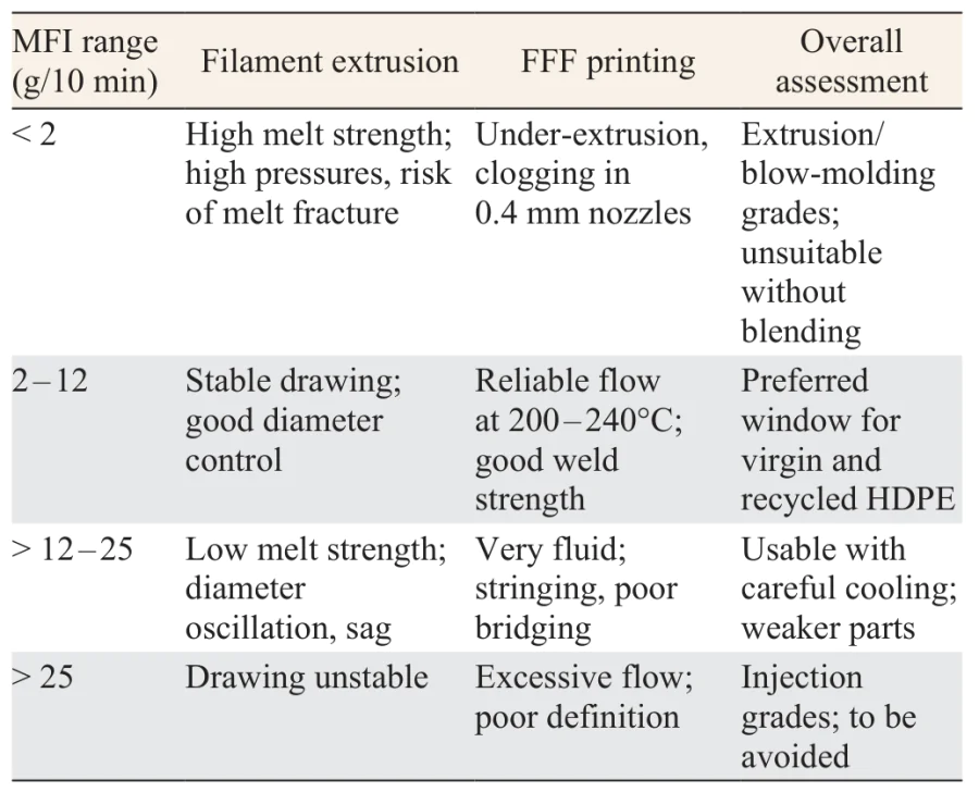
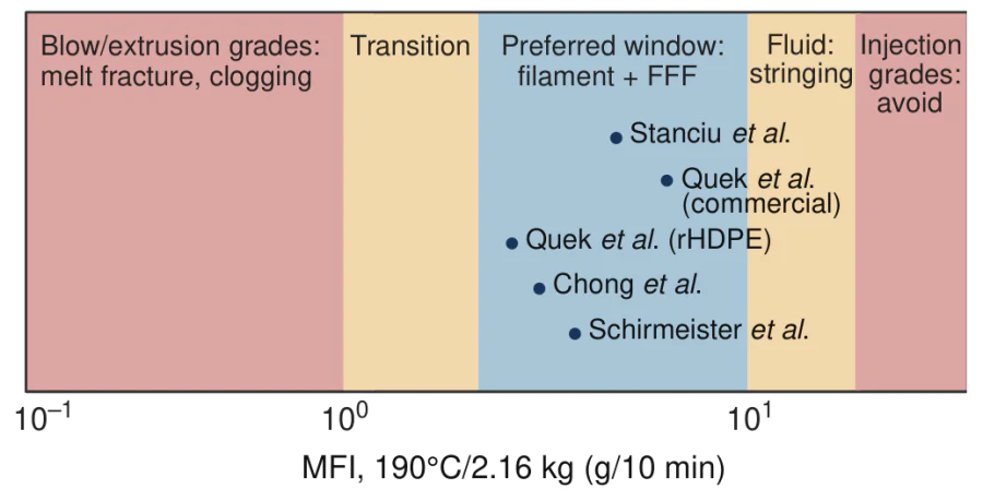
Practically every experimental paper on HDPE printing characterizes its feedstock through the melt mass-flow rate (MFR; commonly referred to as the melt flow index, MFI), measured for PE at 190°C under a 2.16 kg load, according to ISO 1133.[35] Commercial grades cover an enormous range, from below 0.5 g/10 min for blow-molding resins with high melt strength up to more than 20 g/10 min for the injection-molding grades.[3, 34] Filament production and printing place demands that pull in opposite directions, and they meet in an intermediate window. The melt has to pass through a 0.4 – 0.8 mm nozzle at the modest pressures a desktop extruder can generate, which argues for a high MFI; on the other hand, the freshly drawn filament must not sag or oscillate in diameter, and the deposited bead must hold its shape, which argues for a low MFI and high melt strength.[28, 32, 36] The feedstocks behind the successful printing studies fall, almost without exception, between about 2 and 12 g/10 min.[19, 28, 37] Figure 3 visualizes this window along the MFI scale, and Table 2 summarizes how the individual process steps respond across it.
A single-point index, of course, says nothing about elasticity, and the HDPE melt is strongly shear-thinning and viscoelastic. Die swell, the elastic recovery of the extrudate at the die exit, grows with molar mass and with extrusion rate; it alters the effective filament diameter during extrusion and the bead cross-section during printing.[38, 39] Liang[31] measured the melt strength and drawability of HDPE, LDPE and their blends and showed that adding LDPE stabilizes the drawing, an observation filament producers exploit directly. Within the usual processing window, the temperature sensitivity of PE viscosity is comparatively mild; the viscosity still falls noticeably between 190 and 230°C, however, and this lies behind the strong influence of nozzle temperature on extrudability and weld quality discussed in Section 4.[28, 34] Filled systems complicate things further, as montmorillonite and similar rigid fillers raise the low-shear viscosity and introduce yield-like behavior at loadings of only a few percent,[40] something that has to be compensated by a higher printing temperature or wider nozzles. Simulation work on strand deposition[41] and on flow and temperature history inside the hot end[42] shows that the printable window is set by rheology and heat transfer acting together, not by either of them alone.
2.3. Crystallization kinetics and shrinkage
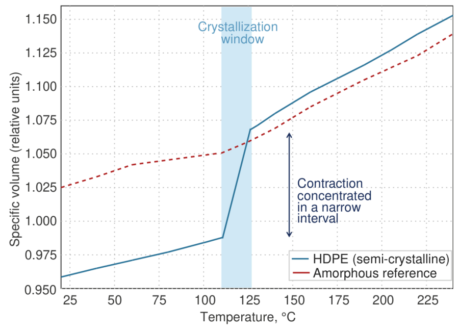
Crystallization deserves its own section, since it is the one phenomenon that separates HDPE most sharply from the amorphous polymers dominating FFF. On cooling from the melt, HDPE starts to crystallize at approximately 115 – 120°C, with most of the transformation completed within a narrow range, whose exact position shifts with cooling rate and nucleation density.[20, 34] The half-times involved run from seconds to minutes, which exactly matches the time scale of layer deposition in a desktop printer; modest changes in layer time, part size or cooling airflow are then sufficient to shift the process between a regime where each strand crystallizes almost at once and one where several layers crystallize together.[25, 43] Vaes et al.[25] demonstrated for polyamide copolymers that interlayer bond strength strongly depends on this interplay between thermal history and crystalline morphology; the same logic applies, to a greater extent, to the faster-crystallizing HDPE. Figure 4 sketches the specific volume – temperature behavior: the crystallization step squeezes most of the total contraction into a few tens of kelvins.
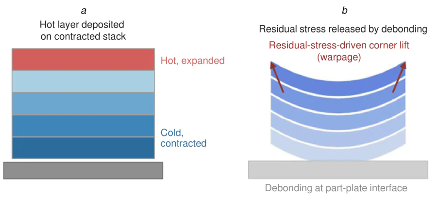
The deposited material is constrained by the layers beneath it; its contraction therefore cannot occur freely and turns into residual stress, which builds up layer by layer and ultimately manifests itself in corner lift, delamination or distortion once the part comes off the plate.[23, 24] Wang et al.[23] derived the basic proportionalities in an early analytical model of FDM warp deformation. Distortion grows with the in-plane length of the part, with the total shrinkage potential of the material and with the number of layers laid down under a thermal gradient. Faster cooling gives smaller spherulites and a somewhat lower final crystallinity, at the price of steeper gradients and more residual stress; slower cooling lets the stress relax, but the build takes longer and the microstructure coarsens.[20, 43] In practice, two further points are important. Nucleating agents raise the crystallization temperature and homogenize the spherulite size, so the interval over which shrinkage develops narrows; dimethyl dibenzylidene sorbitol (DMDBS) acts in exactly this way, both in fundamental studies on polyethylene[44] and printing practice.[24] Nor does crystallization end when the part leaves the printer. Secondary crystallization over hours to days adds a slow contraction of a few tenths of a percent, plus some drift in stiffness, and this is why annealing above the crystallization temperature is so often recommended before a printed HDPE part enters dimension-critical service.[20, 45]
2.4. Thermal degradation during processing and reprocessing
Under inert conditions HDPE is thermally robust; decomposition onsets in thermogravimetric analysis lie typically above 400°C.[34, 37] Real extrusion and printing, though, expose the melt to oxygen, shear and residence times of minutes, and thermo-oxidative degradation then proceeds at ordinary processing temperatures through two competing channels: chain scission, lowering molar mass and raising the MFI, and oxidation-induced branching or crosslinking, acting in the opposite direction.[3, 46] Which of the two channels wins depends on the grade, on the stabilizer package that remains and on the severity of the pass. Oblak et al.[46] put HDPE through one hundred consecutive extrusion cycles and observed the MFI first increasing and then decreasing as crosslinking took over, the mechanical properties degrading gradually rather than abruptly. Jin et al.[47] documented the analogous behavior of LDPE over one hundred cycles. A well-stabilized virgin resin survives a single pass at 180 – 220°C with only minor changes; every further cycle, however, consumes antioxidants and accumulates carbonyl-bearing oxidation products.[46, 48]
A recycled feedstock carries its service history with it into the extruder. Photo-oxidation during outdoor use brings surface embrittlement, carbonyl groups and pre-formed radicals that then accelerate thermal degradation, as the classic weathering studies of PE demonstrate;[49, 50] our group has reviewed the underlying radiation-aging mechanisms elsewhere.[51] Re-stabilization, that is, replenishing the hindered-phenol primary antioxidant and the phosphite secondary antioxidant, with hindered-amine light stabilizers (HALS) added for outdoor products, is for this reason standard advice in the recycling literature.[3, 4] Since degradation shifts the MFI, an incoming recyclate batch should be characterized at minimum by its MFI, and preferably also by differential scanning calorimetry and the Fourier-transform infrared carbonyl index, before it enters filament production.[37, 52] Such measurements cost little and, as Section 3 shows, they anticipate most of the trouble that recycled filament will later cause in the printer.
3. Filament production from virgin and recycled HDPE
3.1. Feedstock preparation
Virgin HDPE is delivered as pellets with certified MFI and density, so it needs little preparation. Polyethylene is not hygroscopic and does not hydrolyze. Surface moisture on regrind and flake still produces voids and diameter fluctuations in the extrudate, though, so a short drying step of 2 – 4 h at 60 – 80°C is common practice.[37, 53] The recycled route is considerably more demanding and the studies that describe it in detail agree on the sequence of collection, sorting away from other polymers, washing off product residues, labels and adhesives, shredding into flakes, drying and, if needed, re-pelletizing.[4, 5, 52] Sorting relies either on near-infrared identification at industrial scale or, in simpler setups, on float-sink separation, HDPE floating in water while PET and polyvinyl chloride (PVC) sink.[4, 54] Chong et al.[37] compared recycled pellets with directly shredded flakes as extruder feed and found both workable, the pellets giving a noticeably better diameter consistency; Angatkina[52] documented the same trend for HDPE recovered from municipal solid waste. Earlier, Hamod[54] showed that bottle-grade HDPE from household waste can become usable filament with laboratory equipment, an observation the distributed-recycling community later built into a system.[5, 55]
3.2. Single-screw vs. twin-screw extrusion
In most laboratory and community-scale studies HDPE filament is extruded on single-screw machines, among them open-source designs that descend from the RepRap ‘recyclebot’ concept.[53, 55, 56] Baechler et al.[56] demonstrated the principle of converting waste polymer into RepRap feedstock, and Woern et al.[55] reported a complete open-source extruder that produces filament from shredded plastic at a cost low enough for household operation. Setiawan et al.[57] designed a pellet-fed HDPE extruder with temperature and speed control aimed specifically at 3D-printing feedstock. A single-screw machine is simple and does the job for clean, single-grade feedstocks; it mixes poorly, though, so the batch-to-batch variability of a recyclate passes straight through into the filament.[36, 53] A twin-screw extruder homogenizes melts of mixed thermal history, disperses fillers and stabilizers and devolatilizes through its vent ports, at the price of a higher investment and more shear heating.[3, 58] The compounding studies reviewed in Section 6, whether with cellulose fillers[58, 59] or with recycled HDPE/PP and HDPE/PET blends,[60-62] rely on twin-screw or purpose-designed mixing screw systems almost without exception. Several groups report a pragmatic compromise, namely two-stage processing: twin-screw compounding into homogeneous pellets, then single screw filament extrusion under tight diameter control.[27, 58]
3.3. Temperature profiles, cooling and diameter control
In HDPE filament extrusion the reported barrel profiles climb from roughly 150 – 170°C in the feed zone up to 180 – 220°C at the die. A die temperature near the lower end of this range, several studies note, works in favor of melt strength and of diameter stability.[28, 32, 53] Stanciu et al.[32] fabricated both LDPE and HDPE filaments at around 160 – 200°C and characterized them for FFF use. Too high a die temperature thins the melt causing the extrudate to sag and the diameter to fluctuate; too low a temperature raises the die pressure and provokes melt fracture and surface roughness.[36, 38] HDPE crystallizes rapidly, so the cooling arrangement matters more here than it does for amorphous filaments. A water bath cools fast and gives good diameter control, but it also quenches a skin-core crystallinity gradient into the strand; air cooling is gentler, at the cost of longer lines and careful tension control.[52, 53] Haul-off speed sets the draw-down ratio together with die swell,[38] and closed-loop control from an in-line diameter measurement remains the most dependable route to the ±0.05 mm tolerance expected of commercial 1.75 mm filament.[4, 53]
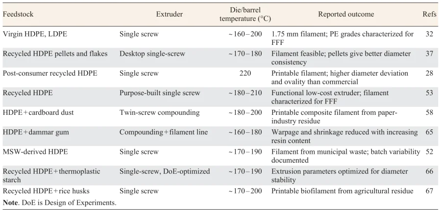
How much filament quality matters downstream, was quantified by Quek et al.,[28] who extruded post-consumer HDPE at 220°C and measured a clearly larger diameter deviation and ovality than in commercial HDPE filament; the irregularity carried through into unstable extrusion during printing and into lower printed-part properties. It follows that diameter statistics, and not only the mean value, form a key acceptance criterion for recycled filament.[5, 28] Woern et al.[63] pointed out a way to sidestep the problem altogether: fused particle (granular) fabrication feeds shredded material straight into a screw-equipped print head, so the filament stage and its tolerances disappear, at the cost of a more complex printer, an approach whose systematic possibilities have been reviewed by Justino Netto et al.[64] Table 3 compiles representative extrusion conditions and outcomes from the literature.
The PE filament-extrusion experience is broader than HDPE alone, and the neighboring studies are instructive. Devra et al.[68] recycled post-consumer LDPE film into printable feedstock and characterized it thermophysically. Wamuti et al.[66] optimized extrusion parameters for a recycled HDPE-thermoplastic starch composite filament by systematic design of experiments; and Andanje et al.[67] produced biofilaments from recycled HDPE and rice husks, showing that agricultural residues can enter the formulation at the extrusion stage. The parameters these groups converge on, feed zone temperatures well below the die, moderate screw speeds and a slow, tension-controlled haul-off, are the same ones the dedicated HDPE studies report, and this suggests the extrusion window of Table 3 holds across feedstock origins.[53, 66, 68]
3.4. Contamination and batch variability of recyclates
Post-consumer HDPE is never chemically pure. The contaminants that keep appearing are PP from closures and mis-sorting, LDPE and LLDPE film fractions, PET from multilayer packaging, pigments, inorganic fines and organic residues.[4, 60] Polyolefin cross-contamination is the mildest case. More than four decades ago, Bartlett et al.[69] established that unmodified HDPE/PP blends keep a near-additive stiffness but embrittle severely at intermediate compositions; morphological analysis of mechanically recycled HDPE/PP blends confirms that the phase structure, and with it the toughness, is highly sensitive to the composition and to the MFI contrast between the phases.[60] A few percent of PP in an HDPE stream costs mainly impact strength. PET is worse. Its melting point lies far above the whole HDPE processing window, so unmelted PET particles survive extrusion and act as stress concentrators, unless the blend is deliberately compatibilized and processed hot.[70, 71] Vaucher et al.[70] studied the mirror-image case of HDPE contamination in bottle-grade PET for printing and reached the same conclusion about mutual incompatibility.
Beyond composition, recyclate batches differ in thermal history, hence in MFI, color and volatile content, and the filament properties drift from spool to spool as a result.[28, 52] The mitigation strategies the literature reports are blending the recyclate with a virgin fraction to buffer the variability,[27, 72] melt filtration to remove solid inclusions,[4] and routine statistical control of MFI and diameter.[5, 53] Oussai et al.[73] and Zander et al.,[74] working with recycled PET, showed that a carefully characterized post-consumer feedstock can come close to commercial filament quality; the HDPE studies reviewed here indicate the same for polyethylene, provided the sorting and washing steps are taken seriously.[28, 37, 52]
3.5. Stabilizers, compatibilizers and chain extenders
Every remelting step consumes stabilizers. Readditivation is thus the cheapest effective intervention a filament producer working with recyclate has at hand. A standard package combines a hindered-phenol primary antioxidant with a phosphite hydroperoxide decomposer at total loadings of a few tenths of a percent, extended with HALS and carbon black or other ultraviolet (UV) absorbers when the printed product is to serve outdoors.[3, 49, 51] Reactive additives go further. Maleic-anhydride-grafted polyethylene (MAPE) couples polar contaminants and fillers to the non-polar matrix and serves as the standard compatibilizer of the wood-plastic literature;[75, 76] Krivoguz[76] reviewed how such compatibilizing agents simultaneously shape structure, flammability and mechanical properties in HDPE systems. For HDPE/PET recyclate, ethylene-glycidyl methacrylate copolymers turn brittle, phase-separated blends into printable materials of useful toughness.[61, 77] Chain extenders based on peroxides or on multifunctional epoxides can rebuild part of the molar mass lost to scission and pull an over-degraded recyclate back into the printable MFI window.[3, 77] What these studies consistently show is that additive investments of the order of a few percent of the material cost widen the processing window and stabilize the properties of recycled HDPE filament far out of proportion to their price.[3, 4]
4. FFF processing of HDPE
4.1. Nozzle, bed and chamber temperature windows
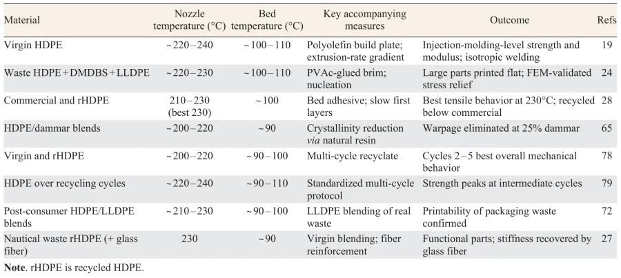
The successful printing reports converge on nozzle temperatures of roughly 200 – 240°C, that is, 65 – 115°C above the melting point: high enough for melt fluidity and interlayer reflow, and still below the onset of rapid thermo-oxidative damage.[19, 28, 65] Quek et al.[28] varied the nozzle temperature between 210 and 230°C and obtained the best tensile strength and modulus at 230°C, for commercial and recycled HDPE filament alike. Schirmeister et al.[19] varied nozzle temperature and diameter systematically; surface quality depended on both, whereas the mechanical properties responded most strongly to the extrusion rate, and deliberate over-extrusion closed the inter-bead voids. Build-plate temperatures of 80 – 110°C appear in almost every study; a hot bed keeps the first layers near the crystallization window, slows down their contraction and reduces the stress mismatch at the part-plate interface.[24, 78] Enclosures and heated chambers flatten the thermal gradient over the whole part. True chamber control is rare on desktop machines, yet several groups attribute their success with larger parts to at least a passive enclosure.[3, 27] Figure 5 brings the reported nozzle and bed combinations together into a single processing map, and Table 4 lists representative parameter sets along with the accompanying measures each study used.
Two more process variables deserve mention, being cheap to change and often decisive. The first is the speed and height of the first layer: a slow, hot, slightly over-extruded first layer gives the bead time to wet the surface before it crystallizes, and nearly every practical report on polyolefin printing adjusts it.[28, 80] The second is the part-cooling airflow that most slicing profiles inherit from PLA practice. For HDPE it is actively harmful, steepening the very gradient that drives warpage and shortening the welding window, and the HDPE studies either switch the fan off or keep it for bridging moves only.[19, 65] Feed-rate limits matter as well, Luo et al.[42] quantified the upper bound that heat transfer in the hot end places on feed rates in material extrusion, a constraint the low-MFI HDPE grades reach earlier than the fluid amorphous polymers.
4.2. Bed-adhesion strategies
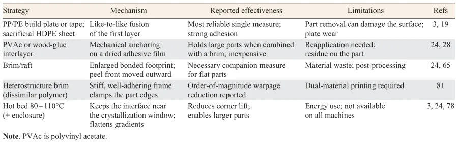
Left unaided, an HDPE first layer detaches from glass, aluminum or polyimide almost as soon as shrinkage stress develops, a direct consequence of the low surface energy of polyethylene.[3, 19] In the literature, three families of countermeasures recur. Table 5 summarizes them together with their reported effectiveness. The first is chemical affinity: print onto a polyolefin surface, be it a PP or PE plate, polyolefin packaging tape or a sacrificial HDPE sheet, and the first layer fuses locally to a like material. Schirmeister et al.[19] identified the polyolefin build plate as the decisive factor for adhesion in their optimization, and the practical reports consistently place such surfaces above every coated glass. The second family is adhesive interlayers. Polyvinyl-acetate glue sticks and wood glue provide mechanical anchoring; Gudadhe et al.[24] combined a glued brim with their nucleated blend to keep large flat parts on the plate, supporting the interpretation with finite-element calculations of the interfacial stress. The third family is geometric anchoring, where brims and rafts enlarge the bonded footprint and push the peel front away from the part edge.[24, 65] Bao[81] took the idea further with a heterostructure brim, printed from a dissimilar and well-adhering polymer that clamps the polyolefin part onto the plate, and reported an order-of-magnitude reduction in warpage. The experience with PP, whose adhesion behavior is nearly identical, corroborates all three routes: Spoerk and co-workers[43, 82] showed that PP adhesion is governed by matching the build-plate chemistry and tuning the first-layer conditions, and Carneiro et al.[80] printed PP successfully on a PP plate.
4.3. Warpage control
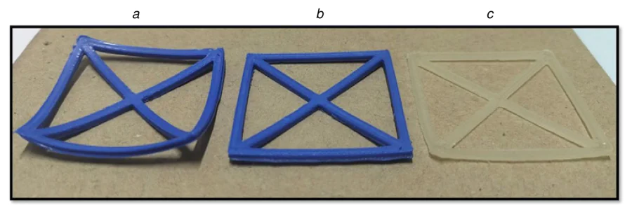
Warpage is nothing more than the visible release of the residual stress that accumulates while constrained layers contract; its mechanics have been modeled since the early days of FDM.[23] Its magnitude scales with the in-plane dimension of the part, with the shrinkage potential of the material and with how steep the thermal gradient is during solidification.[23, 24] Figure 6 illustrates the mechanism. The countermeasures act, accordingly, on three levers. On the material side, the aim is to reduce the shrinkage term itself. Nucleating agents narrow the crystallization interval,[24, 44] partially miscible diluents such as LLDPE lower the overall crystallinity[24, 72] and natural resins do the same. Steven et al.[65] eliminated measurable warpage of HDPE at 25% dammar gum loading, the 12.5% formulation giving the highest tensile strength. Rigid fillers restrain the contraction mechanically, an effect demonstrated for expanded perlite in PP by Spoerk et al.[83] and exploited in the HDPE composites of Section 6. On the process side, the measures act on the gradient and on the constraint, that is, hot beds, enclosures, less part-cooling airflow, slower first layers, and an adhesion strong enough for the stress to relax by creep rather than by debonding.[3, 28] The third lever is geometry: rounded corners, ribs in place of solid slabs and moderate infill densities all lower the peak interfacial stress,[3, 81] while at the slicing level, infill sectioning strategies that break up long continuous rasters have also been shown to mitigate warpage.[84] One practical point comes up in all the studies: a single measure is not enough for large flat HDPE parts, and every demonstration that succeeded combined at least one intervention from each of the three groups.[19, 24, 65]
What these measures accomplish is easy to see. Figure 7 contrasts the pronounced corner lift of a frame printed from unmodified recycled HDPE with the essentially flat frames obtained from an rHDPE/LLDPE 70/30 blend and from neat LLDPE.[85]
4.4. Interlayer diffusion and bonding
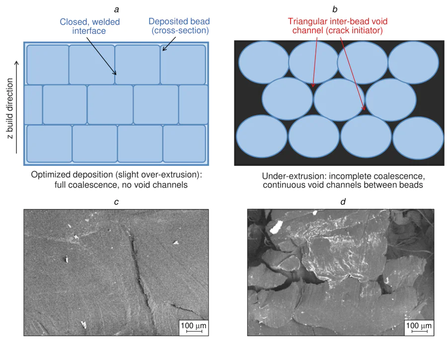
The strength between layers in material extrusion builds up in stages. The surfaces wet, come into intimate contact, and the polymer chains then interdiffuse across the weld line. This is the classical healing picture that Wool and O’Connor[86] formulated and that Yang and Pitchumani[87] later adapted to non-isothermal processing. All three stages are thermally activated; for a semi-crystalline polymer, they effectively stop the moment the interface crystallizes.[25, 26] Seppala et al.[26] measured weld temperatures during printing and showed that the time available for welding amounts to seconds. Coogan and Kazmer[88] built healing-based models predicting FFF bond strength from that thermal window; their later rheological work established the role of the interlayer contact pressure.[89] For an amorphous polymer the welding window extends all the way down to the glass transition. For HDPE, the weld has to form in the short interval before the interface crystallizes, typically a few seconds under desktop conditions.[19, 25] A high nozzle temperature, thick beads, low cooling airflow and short interlayer times all lengthen this window or exploit it better, in direct tension with the preference of warpage control for cool, calm deposition. The practical optimum is a compromise and is usually found near the upper end of the bed-temperature range and the middle of the nozzle range.[3, 28]
What is achievable can be seen from two observations. Schirmeister et al.[19] reached an essentially isotropic tensile strength, equal parallel and perpendicular to the deposition direction, which demonstrates that HDPE welds can reach bulk cohesion when the reflow is sufficient; the fast segmental dynamics of the PE melt work in the printer’s favor once the thermal budget exists. Conversely, Quek et al.[28] traced the inferior z-direction performance of their recycled filament back to diameter irregularity, which produces local under-extrusion and unbonded patches. Void content is the second determinant of weld-limited strength. Insufficient flow leaves triangular inter-bead channels that act as crack initiators, and the over-extrusion gradient of Schirmeister et al.[19] was aimed precisely at eliminating them. Figure 8 shows the two cross-sectional microstructures involved, well welded beads with closed interfaces on the one hand and under extruded beads with triangular void channels on the other. The same contrast is documented in SEM cross-sections of FFF HDPE specimens, where fully fused, void-free deposition and open interlayer gaps coexist depending on processing history.[79] Heat transfer simulations of the weld region[90] and non-isothermal flow models[41, 42] now allow these effects to be anticipated instead of discovered empirically, although their application specifically to HDPE is still sparse.
5. Properties of printed HDPE parts
5.1. Tensile and impact behavior vs. injection-molded baselines
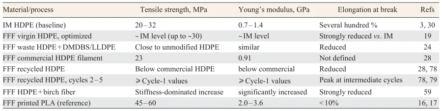
Any comparison has to start from IM HDPE. A molded specimen, depending on grade, formulation, and crystallinity, reaches an ultimate tensile strength of 20 – 32 MPa, a Young’s modulus of 0.7 – 1.4 GPa and an elongation at break of several hundred percent.[3, 30] It should be noted that some commercially available HDPE filaments, such as low-warp formulations, may contain additives that shift mechanical properties–particularly stiffness–beyond the range of neat HDPE, and results from such materials should not be treated as directly equivalent to unfilled grades. Zuraimi et al.[30] give representative molded values, and Leyva-Porras et al.[91] showed for PE how strongly the molding parameters themselves shift microstructure and crystallinity. In other words, the ‘baseline’ represents a range rather than a point. For FFF technology, the central question is how much of this envelope a printed part retains under optimized conditions. The answer is, in strength and stiffness at least, most of it. Schirmeister et al.[19] reported printed HDPE with a tensile strength and Young’s modulus equal to IM references. Elongation at break was the one property that stayed far below the molded value, a reflection of weld lines and residual voids that localize the strain. Gudadhe et al.[24] measured properties close to unmodified bulk HDPE for their nucleated waste derived blend. Vidakis et al.[92] provide a further point of reference for material extrusion HDPE in their filler study, and the technical data of early commercial HDPE filaments overlap with this performance range for tensile strength, though stiffness values vary more widely depending on formulation.[93]
With recycled feedstocks the spread becomes wider. Quek et al.[28] measured a systematically lower strength and modulus for printed recycled HDPE than for printed commercial HDPE and put the deficit down to degradation history and filament irregularity. Tipu et al.,[78] on the other hand, reprocessed HDPE through five cycles and found that specimens printed from the intermediate cycles matched or exceeded the first-cycle properties, an effect they explained through improved homogenization; Section 7 returns to this point. Impact behavior benefits from the intrinsic ductility of polyethylene. Printed HDPE generally fails in a ductile manner at room temperature and compares favorably with the brittle fracture of printed PLA, though the weld lines cost some toughness relative to molded HDPE.[3, 78] Figure 9 summarizes indicative tensile-strength ranges for molded HDPE, printed virgin, recycled and composite HDPE, and printed PLA as a reference, and Table 6 compiles the study-level data.
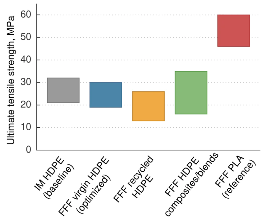
Here, a note on comparability cannot be avoided. The studies compiled in Table 6 used different specimen geometries, print orientations, infill densities and testing speeds; the tensile standards themselves permit that variety.[94] The strengths reported for nominally similar materials thus differ by amounts that have nothing to do with the polymer, a problem the systematic reviews of recycled-filament performance keep flagging.[5, 29] Until printed-polymer testing converges on shared protocols, a single-study value should be read as a point inside the bands of Figure 9, not as a material constant.
5.2. Mechanical anisotropy
Parts built from extruded strands are usually weakest across the layers, and the degree of anisotropy serves as a sensitive index of weld quality. According to the classic characterization of FDM anisotropy conducted by Ahn et al.,[95] the cross-layer strength of ABS is only a fraction of the in-plane value; similar behavior have since been observed in, most FFF materials.[9, 96] Against this background, the HDPE record appears unusually high. Poorly bonded prints with visible inter-bead voids show strong anisotropy,[28] while the optimized prints of Schirmeister et al.[19] were essentially isotropic in tensile strength. This spread confirms the mechanistic picture of Section 4.4, in that the z-strength of HDPE is limited not by the polymer itself but by the thermal budget the weld is granted. Within the layer plane, raster orientation brings in the familiar second-order anisotropy: rasters aligned with the load outperform transverse ones, while crossed ±45° strategies give intermediate and more balanced behavior.[78, 95] In fiber filled HDPE, flow-induced fiber alignment along the deposition direction adds a further, often dominant, contribution,[59, 97] and design has to respect it or exploit it.
5.3. Dimensional accuracy and stability
Dimensional error in printed HDPE comes mostly from three sources, viz., the immediate shrinkage during the build, the distortion induced by warpage, and a slow post-print contraction due to secondary crystallization.[21, 45, 65] The linear shrinkages reported for unmodified HDPE prints are of the order of 2 – 5%, several times what PLA or ABS give under comparable conditions,[21, 65] and the thermal-expansion measurements of Bute et al.[22] show why printed polyolefin parts keep moving with temperature in service. Compensation works at three levels: a global scale factor in the slicer, calibrated per material batch;[28, 52] modification of the material, since nucleation, fillers and blending lower the shrinkage potential itself;[24, 58, 65] and annealing after the print, which brings the part to its stable dimensional end state before finishing.[45, 78] When the measures are combined, deviations below 1% have been reported for moderate part sizes,[19, 65] but tolerance critical features still call for machining allowances, as Burkhardt et al.[98] concluded even for professionally optimized polyolefin prints intended for medical use.
5.4. Environmental aging, chemical resistance and long-term behavior
One of the strongest arguments for printing HDPE at all is its chemical resistance. The polymer withstands acids, bases, alcohols and aqueous media and swells appreciably only in non-polar solvents at elevated temperature; a printed part inherits this resistance essentially unchanged, though its larger surface area and its inter-bead crevices speed up the uptake kinetics.[3, 37] The water absorption of printed recycled HDPE stays very low, and this supports outdoor and wet applications.[37, 78] The principal environmental threat is photo-oxidation. UV exposure embrittles polyethylene surfaces,[49, 50] and a printed part, with its thin bead walls and its stress concentrations at the bead junctions, is more sensitive than its molded equivalent.[51] For HDPE/wood-flour composites, Nguyen et al.[99] showed that a protective shell bearing basalt fiber slows weathering down substantially. Conventional HALS/carbon-black packages are advisable for any printed HDPE headed for prolonged outdoor service, in high insolation agricultural environments above all.[49, 51]
The long-term mechanical record is much thinner. Even at room temperature, HDPE creeps significantly under sustained load, and a printed part adds its weld interfaces as extra compliance sites. Systematic creep data for printed HDPE remain scarce, and the fracture-mechanics methodology that Arbeiter et al.[100] applied to FFF parts for lifetime estimation has yet to be transferred to PE. Fatigue in FFF has been reviewed by Bakhtiari et al.,[96] again with hardly any HDPE data points. Environmental stress cracking, the classical slow-failure mode of polyethylene assessed by the full-notch creep test of ISO 16770,[101] has, to our knowledge, never been measured on printed HDPE at all, even though the weld lines of a printed part are exactly the place where such a failure would start. Section 9 picks these gaps up again as research priorities.
6. Modified and composite HDPE systems
6.1. Nucleating agents and crystallization modifiers
Among the material-side interventions for HDPE printability, nucleation is the most surgical one. Sorbitol-derived nucleators such as DMDBS act at fractions below 0.5 wt.%; they raise the crystallization temperature, refine and homogenize the spherulites and, in doing so, narrow the temperature interval over which shrinkage develops.[24, 44] Mitchell et al.[44] examined the dibenzylidene sorbitol-polyethylene system at the structural level by neutron scattering, and Gudadhe et al.[24] supplied the proof on the manufacturing side: waste HDPE with DMDBS and about 10% LLDPE went from unprintable to reliably printable, large flat parts staying on the plate thanks to a glued brim. The opposite strategy is to suppress crystallinity with amorphous or low-crystallinity diluents. Steven et al.[65] blended HDPE with dammar gum, a natural resin, and observed shrinkage and warpage falling monotonically with the resin content; warpage vanished at 25% loading, and the 12.5% formulation gave the best tensile strength. Comparable resin-blending logic has been applied to PP printing with hydrocarbon resins and nucleation packages,[102] an indication that the approach carries over to the other polyolefins as well. Both routes give up a little stiffness and heat resistance in exchange for large gains in dimensional stability, and both run on unmodified extrusion equipment.[24, 65]
6.2. Mineral and carbon fillers
Rigid fillers hold shrinkage back mechanically and raise the modulus, and when the filler is conductive, it adds function as well. At the nanoscale, montmorillonite at loadings of only a few percent raises melt viscosity and stiffness and still stays within a manageable rheological window.[40] Graphene nanoplatelets raise crystallinity, modulus and, above all, thermal conductivity, with an efficiency that depends on the relative size of the platelets and the polyethylene chains.[20, 103] Multi-walled carbon nanotubes at low loadings improve strength, stiffness and wear resistance,[104] and this motivated the printed HDPE gearing demonstrations,[105] and carbon-network fillers make printed polyethylene structures electrically conductive, as Gnanasekaran et al.[106] showed for carbon nanotube (CNT)- and graphene-filled polymers printed by desktop FDM. Vidakis et al.[92] mapped the property optimum of zinc-oxide micro-filled HDPE in material extrusion and found the usual composite compromise between stiffness gained and ductility lost. At the opposite end of the cost scale, mineral and industrial byproduct fillers cut price and shrinkage at the same time: coal fines remained extrudable and printable up to high loadings, with a usefully modified thermophysical behavior,[107] and formulation principles established in classical studies of filled-HDPE (using talc, calcium carbonate, glass spheres and metal powders[108, 109]) are applicable to printing processes with few changes. Phase-change composites in polyethylene matrices have been printed for thermal-management packaging.[110, 111] Across all these systems the constraints that keep coming back are viscosity growth, nozzle abrasion by the hard fillers and filler-matrix adhesion. The last one motivates the coupling agents of the next subsection.[40, 97]
6.3. Natural fibers and compatibilized composites
Lignocellulosic reinforcement pairs naturally with recycled HDPE in sustainability-driven products. The mechanical-property landscape of natural-filler FDM materials has been reviewed by Mazzanti et al.[97] Koffi et al.[59] printed HDPE with birch fibers and obtained a stiffness increase at moderate fiber content, with acceptable processability. Gregor-Svetec et al.[58] formulated printable filaments from HDPE and cardboard dust, valorizing a paper-industry residue; and the wider wood-plastic composite experience, from thermoformed wood-flour boards[112, 113] to hemp-HDPE compounds,[114] supplies well-tested formulation rules. Polyolefins being non-polar, fiber-matrix adhesion needs coupling, and the standard answer is MAPE: Hao et al.[75] resolved its interfacial mechanisms even at very high wood-fiber loadings, and Poletto[115] showed for recycled PP how coupling agents improve rheology, thermal expansion and morphology all at once, findings that carry over to the HDPE systems.[76, 116] Natural fibers cut shrinkage and cost and raise the modulus; the price is a lower elongation, sensitivity to moisture and a processing ceiling near 200°C to keep the cellulose from degrading, a limit that happens to sit comfortably inside the HDPE window.[59, 97] For outdoor service, UV-protective strategies such as the basalt-fiber shell of Nguyen et al.[99] address the weathering sensitivity of the wood fraction. Parallel evidence from recycled-PP natural-fiber printing[117, 118] and from glass-fiber reinforcement of nautical-waste HDPE[27] confirms that adding fiber is also the most direct way to win back the stiffness lost to recycling.
6.4. Polyolefin and HDPE/PET blends
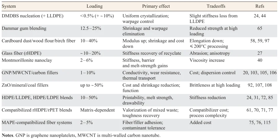
Blending allows the stiffness-toughness-printability balance to be tuned without leaving the polyolefin family. HDPE/LDPE blends raise melt strength and drawability during filament production.[31] HDPE/LLDPE blends lower crystallization stress, and Pritoni et al.[72] printed post-consumer HDPE/LLDPE blends directly, confirming the approach on real waste streams. Gopal et al.[85] recently formulated recycled HDPE for low warpage and high toughness along the same lines. Schirmeister et al.[119] took the concept to its logical end, with all-polyethylene composites in which oriented UHMWPE-rich nanostructures form during the printing itself. Across polymer families the picture is harsher. Unmodified HDPE/PP embrittles at intermediate compositions,[60, 69] although controlled processing can turn the incompatibility into a microstructural advantage: Leng et al.[120] tailored the crystalline structure of iPP/HDPE blends through the printing speed itself, improving the impact strength, and Zhang et al.[62] toughened recycled PP with HDPE using mixing-screw plasticization in screw-based printing. The technologically important HDPE/PET pairing, which mirrors real packaging waste, is immiscible and brittle untreated,[70] but compatibilized rPET/rHDPE (rPET is recycled PET) blends have been pellet printed into functional parts,[77] mixed post-consumer PET/HDPE has been processed by material extrusion in a distributed-recycling context,[71] and screw-design-assisted dispersion raised the toughness of recycled PET/HDPE prints substantially.[61] HDPE has even been paired with PETG in dual-material 3D/4D printing that exploits the property contrast of the two polymers for shape-memory structures.[45] Table 7 summarizes the modified and composite HDPE systems discussed in this section.
7. Recycled HDPE and closed material loops
7.1. Property retention over repeated processing cycles
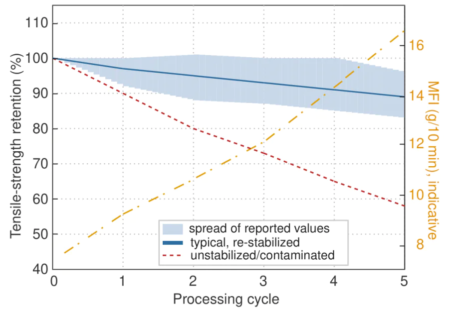
Whether HDPE loops can be closed in additive manufacturing depends on how gracefully the polymer degrades over successive melt cycles; on this point, the evidence is, unusually, reassuring. The reference experiment predates 3D printing: Oblak et al.[46] re-extruded HDPE one hundred times and found the material processable throughout, its properties evolving from an initial chain-scission stage into a slow crosslinking-dominated one; nothing resembling a sudden failure occurred. Within the printing context, Vidakis et al.[79] carried HDPE through multiple recycling and printing cycles and measured the mechanical response systematically. Specific strength metrics peaked at intermediate cycles and declined afterwards. Tipu et al.[78] reported the same non monotonic pattern over five cycles, cycles two to five giving the best overall tensile and impact behavior in their series, something they attributed to progressive homogenization. Chong et al.[37] found recycled HDPE filament comparable to virgin-based references in thermal stability and water absorption, and Zeng et al.[48] showed that blending the recyclate with virgin HDPE brings crystallization behavior and mechanical properties back in proportion to the virgin fraction. The cost shows up on the quality side rather than on the property side: Quek et al.[28] documented lower MFI consistency, higher ovality and reduced strength for post-consumer filament against its commercial counterpart. In mechanistic terms every cycle consumes stabilizers and shifts the molar mass (Section 2.4), so retention comes down to re-stabilization and to the severity of each pass.[3, 46] Figure 10 summarizes the qualitative picture that these studies assemble: when stabilization is adequate, tensile strength typically remains within roughly 85 – 100% of the virgin value over three to five cycles, with the MFI drifting, whereas feedstocks that are unstabilized or contaminated fall away faster.[28, 78, 79] For comparison, the same multi-cycle methodology applied to PETG[121] and to PP composites[122] shows that HDPE is no outlier, it sits among the more forgiving of the recyclable printing polymers.
7.2. Distributed recycling into filament and parts
Filament extrusion is compact and cheap; HDPE recycling thus becomes one of the few branches of polymer recovery that can be decentralized to the scale of a community, a farm or a single facility. The energy case for this concept of distributed recycling for additive manufacturing (DRAM) is documented: the life cycle analysis of Kreiger et al.[12] found that turning post-consumer HDPE into filament locally can consume less embodied energy than conventional centralized recycling, mostly because transport and intermediate pelletizing are avoided, and Zhong et al.[123] showed that a solar-powered recyclebot pays back its energy quickly. At the open-source level, the hardware chain is now complete: recyclebot-class extruders turn washed flake into filament,[53, 55, 56] fused particle print heads accept regrind directly,[63, 64] and even cable-suspended large-format printers running on recycled particles have been published as open hardware.[124] Case studies span nautical waste,[27] municipal solid waste,[52] packaging streams[28, 72] and mixed HDPE/PET feedstocks,[71] while the network side, the meeting point of collection, printers and demand, has been optimized in closed-loop supply chain models.[13] The DRAM literature on other polymers, from PET flake[73, 74, 125] to composite windshield wiper waste,[126] reinforces a conclusion the systematic reviews state directly: on availability and property retention HDPE ranks among the most promising DRAM polymers, quality assurance being the binding constraint.[4, 5, 29] For agricultural regions in particular, an on-site loop that turns used containers and films into fittings, housings and replacement parts shortens the supply chain in both directions, a scenario we have argued for previously.[12, 14]
7.3. Cost aspects and the European regulatory framework
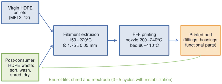
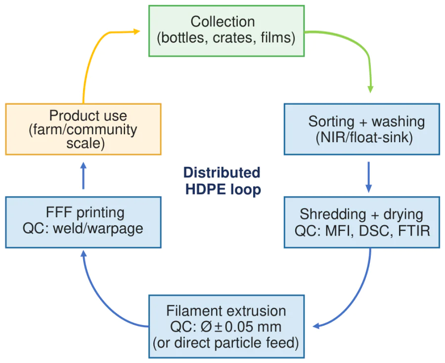
The economics rest on the wide raw material price spread. Post-consumer HDPE flake trades at a small fraction of the price of commercial filament. Even low throughput extrusion therefore adds value, and the studies cite cost next to sustainability as the motivation for HDPE DRAM.[12, 53] The energy cost of extrusion is modest next to the value added, and a distributed model saves the logistics of waste export and of filament import at once.[12, 123] Regulation now pushes in the same direction. The policy frame was set by the European Circular Economy Action Plan,[127] and regulation (EU) 2025/40 establishes minimum recycled-content requirements for specified plastic-packaging categories, with 2030 targets subject to the conditions set in Article 7 of that Regulation;[128] this expands at the same time the supply of sorted HDPE recyclate and the demand for recycling pathways that are demonstrated and documented. Additive manufacturing offers a high-value outlet for that recyclate, and the property-retention datasets of Section 7.1 are exactly the raw material that certification and standardization will ask for.[5, 29] On the institutional side, what is still missing is a recognized specification for AM-grade recyclate and harmonized test protocols for printed recycled parts; tensile testing follows ISO 527 (see[94]) in most studies, but sample geometry, print orientation and conditioning vary enough that direct comparison becomes difficult.[3, 29] Figure 11 sketches the distributed HDPE loop with material flow and quality-control checkpoints.
8. Comparative assessment and applications
8.1. HDPE vs. PLA, ABS and PP
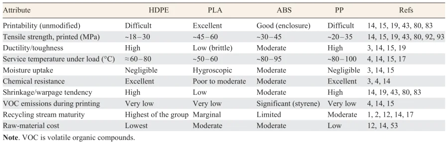
Table 8 provides the comparison that has been building up through this review. On printability and stiffness PLA remains unbeaten; it is, however, thermally limited, brittle and, in practice, rarely recycled, industrial composting and chemical loops staying marginal.[14, 17] ABS prints well in enclosed machines and tolerates higher service temperatures, but it emits styrene-bearing volatiles during printing and its recycling infrastructure is limited.[4, 18] PP is the closest relative of HDPE sharing both its advantages and its disadvantages, semi-crystalline shrinkage, poor bed adhesion, excellent chemical resistance, with somewhat better temperature resistance and, for the moment, better commercial filament availability; its printing problems have been solved by exactly the toolbox of Section 4.[43, 80, 83, 129] What sets HDPE apart within this quartet is the combination of chemical inertness, toughness, negligible moisture uptake and the lowest raw-material cost of the group, together with, decisively, the most mature recycling stream of any FFF-relevant polymer.[1, 3, 4] When ease of printing dominates the requirement list, HDPE is not the rational choice and will not become one; when recyclability, chemical service or feedstock cost dominate, it increasingly becomes one.[12, 14]
8.2. Demonstrated applications
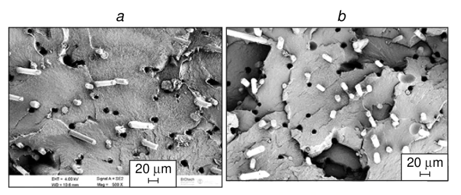
The demonstrations published so far cluster in four areas. The first covers functional consumer and industrial components, housings, containers, fittings and chemically exposed parts, all of which exploit resistance and toughness.[3, 19, 98] The second concerns engineering components from composite HDPE: printed gears and wear parts from MWCNT-filled material,[105] conductive structures from carbon-filled PE,[106] and thermal-management and phase-change packaging.[110, 111] The third covers sustainability-driven products from recycled HDPE, from the nautical waste components of Rigotti et al.[27] to packaging waste parts in DRAM case studies[28, 71] and agricultural scenarios where containers and films are recycled on site into replacement parts.[12, 14] The fourth is the emerging multi-material and 4D niche, exemplified by HDPE – PETG shape-memory structures[45] and by digitally oriented all polyethylene composites.[119] In printed shape-changing structures more generally, the printing process parameters themselves have been shown to govern the extent, accuracy and reproducibility of the shape transformation.[130] Figure 12 shows SEM micrographs of recycled HDPE components printed from nautical waste, and it can be observed that specimens obtained through 3D printing exhibit a degree of surface irregularity that is closely associated with the flow of the printing material and the sequence of the layer deposition process.[27] Liu et al.[45] illustrate the multi-material end of the spectrum. In all four areas the design cautions that recur are the same: respect the service ceiling of roughly 60 – 80°C under load, design for anisotropy unless isotropic welding has been verified, and budget for shrinkage in every tolerance critical feature.[3, 19, 98]
8.3. Design guidelines for printed HDPE parts
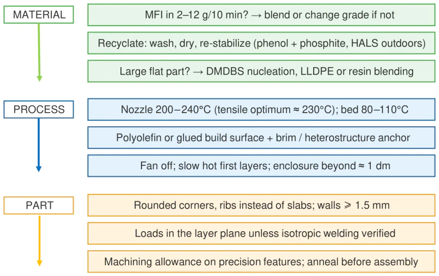
The practice of Sections 3 – 7 is gathered in Figure 13 as a decision sequence, and it can be read at three levels. Starting from the material: the MFI should be checked first, with a target of roughly 2 – 12 g/10 min.[19, 28, 37] Recyclates should be re-stabilized as a routine step[3, 46] and for large flat geometries, nucleation, LLDPE or resin blending should be considered.[24, 65, 72] On the process side, the nozzle ranges at 200 – 240°C, with the tensile optimum near 230°C,[28] the bed at 80 – 110°C,[24, 78] the build surface should be polyolefin or glued, combined with brim or heterostructure anchoring,[19, 24, 81] part cooling airflow should stay minimal, first layers slow and hot, and parts beyond roughly a decimeter ask for an enclosure.[3, 27] At the level of the part itself, corners should be rounded and ribs preferred over solid slabs,[23, 81] walls should stay above about 1.5 mm, and the principal loads should lie within the layer plane unless the weld quality has been demonstrated.[19, 95] Precision features need machining allowances,[98] load bearing or dimensionally critical parts should be annealed before assembly[45, 78] and whatever will live outdoors needs UV stabilization.[51, 99]
9. Conclusion and outlook
HDPE entered the additive manufacturing literature as a notoriously unprintable polymer. After the past decade of research, it leaves it as a demonstrably printable one. The evidence assembled here shows that for each of the three canonical barriers validated countermeasures now exist. Crystallization shrinkage and warpage can be brought under control with nucleating agents, blends and resins that reduce crystallinity, rigid fillers, hot beds, enclosures and anchoring geometries. Bed adhesion is solved most reliably by polyolefin build surfaces together with glued or heterostructure brims. Interlayer bonding, finally, reaches bulk cohesion when nozzle temperature, bead geometry and layer timing give the weld its few seconds of thermal opportunity. Under such coordinated control printed HDPE reaches IM stiffness and strength, elongation at break being the one deficit that persists, and in the best reported case its welding is essentially isotropic. Recycled HDPE takes part almost on a par with virgin resin, provided it has been sorted, washed, characterized and restabilized; it keeps the bulk of its mechanical performance over three to five cycles, and the distributed recycling hardware chain that would exploit this, from open-source filament extruders to particle-fed printers, exists already.
The barriers that remain are infrastructural more than scientific, and they can be ordered into four research and development priorities. The first is standardization. No recognized material specification exists for HDPE printing filament or for AM-grade recyclate, and the heterogeneous test conditions frustrate any comparison between studies. Harmonized MFI, diameter and mechanical acceptance criteria would probably be the single most enabling step the field could take. The second is long-term data. Creep, fatigue, environmental stress cracking and weathering of printed HDPE remain almost uncharacterized, and the interaction between the contamination spectrum of a recyclate and printability is known only anecdotally. Systematic aging studies of printed recycled HDPE would close the gap this review ran into most often. The third is equipment. Heated chambers, polyolefin build surfaces and screw-based pellet printers, were they more widely available, would remove most of the remaining practical friction. Pellet printing, in particular, shortens the recyclate-to-part chain by removing the filament stage altogether. The fourth is model-based process design. The processing maps compiled here ought to evolve into quantitative, simulation-backed windows connecting grade properties, above all the MFI and the crystallization kinetics, to printable geometry envelopes, building on the weld formation and warpage models that already exist. Given the production volume of HDPE, the maturity of its recycling stream and the regulatory momentum behind recycled content in Europe, closing these four gaps would move HDPE from a difficult niche material toward becoming the default sustainable commodity polymer of extrusion-based additive manufacturing.
10. List of abbreviations
- ABS — acrylonitrile-butadiene-styrene;
- AM — additive manufacturing;
- DMDBS — dimethyl dibenzylidene sorbitol;
- DRAM — distributed recycling for (into) additive manufacturing;
- FDM — fused deposition modeling;
- FFF — fused filament fabrication;
- HALS — hindered-amine light stabilizers;
- HDPE — high-density polyethylene;
- IM — injection-molded;
- iPP — isotactic polypropylene;
- LDPE — low-density polyethylene;
- LLDPE — linear low-density polyethylene;
- MAPE — maleic-anhydride-grafted polyethylene;
- MFI — melt flow index;
- MWCNT — multi-walled carbon nanotubes;
- PE — polyethylene;
- PET — poly(ethylene terephthalate);
- PETG — glycol-modified poly(ethylene terephthalate);
- PLA — polylactic acid;
- PP — polypropylene;
- PVAc — polyvinyl acetate;
- rHDPE — recycled HDPE;
- rPET — recycled PET;
- UHMWPE — ultra-high-molecular-weight polyethylene;
- UV — ultraviolet.
References