Keywords
Abstract
Hydrogen has emerged as a major energy vector in the past few years; however, its storage and long-distance transportation remain the key challenges to its widespread use. Ammonia is considered to be a potential medium for hydrogen carrier and storage. Indeed, ammonia is more energy dense than hydrogen, easier to transport, and allows for a CO2-free alternative fuel that could be used in a variety of power generations system. In this regard, solid oxide fuel cell (SOFC) technology stands out as the most promising one that directly converts ammonia into electricity with high efficiency. As SOFCs operate at high temperatures (>600°C), they do not require additional energy for external reforming and cracking of ammonia. In this paper, we critically review the experimental demonstration, major achievements, progress, and prospects in direct NH3-fueled SOFCs.
The bibliography includes 147 references.
1. Introduction
The Net Zero Scenario 2050 has come to the centre stage for researchers and policymakers alike. The issue of climate change calls for urgent measures to decarbonize the environment and curb rising global temperatures. Currently, 80% of global energy consumption per annum is derived from fossil fuel-based energy sources.[1][2] However, in a recent report published by the International Energy Agency (IEA),[3] a strong shift was observed towards renewable energy sources. As a result, the rising global temperature was slowed down, although this temperature is unlikely to stabilize or decrease in the near future (Fig. 1). The contributions of «energy researchers» have seemed to put the global situation on the right track, but tremendous efforts are still needed. The unpredictability of renewable energy resources and the long-standing issue of energy storage are still bottlenecks to a net-zero future.[4-7]
![[{"id":"iDu_w0Na2Z","type":"paragraph","data":{"text":"A visual representation illustrating the anticipated changes in primary energy consumption across various sources from the year 2010 to 2050.<sup>7</sup>"}}]](/storage/images/resized/aO2lPlhu67ymmC1JQa2OmEAYfJwxGihnJZWXxHzh_xl.webp)
Due to the current global situation, renewable resources must be utilized as much as possible. Two aspects of this strategy require particular attention: efficient energy conversion and reliable energy storage.[8-11]
Numerous energy conversion methods have surfaced in the past decade, e.g., fuel cells,[12-17] solid-state batteries,[18-20] perovskite solar cells,[21][22] and advanced wind turbines.[23-28] Among the many areas, conventional hydrogen-fueled solid oxide fuel cells (SOFCs) have attracted considerable attention.[29-37] SOFCs are composed of a ceramic electrolyte sandwiched between porous electrodes that convert the chemical energy of the fuel into electricity via one electrochemical route, avoiding thermal and mechanical energy conversion stages (Fig. 2a). Moreover, SOFCs typically operate at temperatures above 600 °C which overcomes sluggish oxygen reduction reaction (ORR) kinetics;[38-42] their operation is also clean as no greenhouse gas is emitted.[43-46]
![[{"id":"im5m99HvlZ","type":"paragraph","data":{"text":"(<i>a</i>) Schematic illustration of direct ammonia SOFC operation compared to conventional (hydrogen fueled) SOFCs and (<i>b</i>) research activity in direct ammonia SOFC field according to different keywords combination through the Scopus database."}}]](/storage/images/resized/Zo8C6yybuqco1mxgeYKGRwTMDKN0qvEtiuvniw9k_xl.webp)
Significant research efforts have been reported in the literature to advance hydrogen-driven SOFC technology to its full commercial market potential, e.g., to address degradation issues and enhance long-term durability[37][47-55] Nevertheless, even after successful commercialization, hydrogen as a fuel today is not ideal in terms of storage, handling, and safe operation[56-59] Hydrogen as a fuel possesses many excellent characteristics; it generates electricity in a simple oxidation reaction that produces no harmful product or greenhouse gas.[60] Next to nuclear energy, it has the highest heating value (HV) of 141.7 MJ/kg,[61] thus producing a system with up to 50% efficiency when supplied to a combined heat and power (CHP) SOFC unit.[62] However, hydrogen is expensive to store because it has a low volumetric energy density (0.01 MJ/L at stp) and therefore occupies a huge volume at ambient conditions.[63-66] Moreover, its low ignition enthalpy (roughly one-tenth that of gasoline), wide flammability range (4 – 75 vol.%), and high deflagration index incur additional risk, cost, and caution for its storage and handling.[67][68] Another problem with hydrogen storage is its relatively high cost. Physical storage of hydrogen requires either very high pressure (up to 70 MPa) or cryogenic temperatures (20 – 30 K at 1 MPa).[69] These two methods account for a major portion of estimated energy costs in the total input costs of SOFC. In addition to cost, public acceptance of cryogenic low pressure or ultra high pressure systems is surprisingly low.[70] Other than physical storage, several chemical methods such as solid-state hydrogen storage or metal hydrides have been studied but no reasonable advancements have yet been made in this area.[71] Here, the dilemma for researchers is to have a high-energy density fuel with no greenhouse gas emissions or to keep the overall cost of this environmentally friendly solution low. While methane and other carbon-based fuels possess a high energy density, they are major contributors to global warming.[72-75]
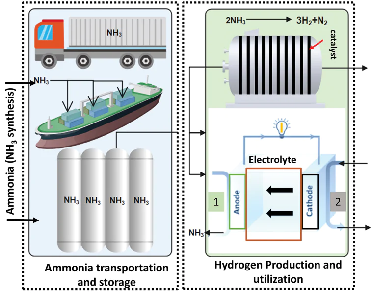
Ammonia as a candidate for SOFC fuel appears to offer a solution to the drawbacks associated with hydrogen if significant development is undertaken to develop direct ammonia SOFC (DA-SOFC).[76-82] As can be seen from Fig. 2b, ammonia decomposition as a way to produce hydrogen fuel for DA-SOFCs attains a competitive position among SOFCs supplied with other fuels; this confirms the potential prospect of DA-SOFCs. Given the well-established ammonia distribution network and the regulated handling and storage methods, ammonia occupies an unique position as a potential fuel for SOFCs. While ammonia offers numerous advantages over hydrogen, there are critical areas that warrant research and development to enable its widespread commercial use. One notable challenge lies in public perception and safety concerns around ammonia. Furthermore, while existing pipelines can facilitate ammonia transportation, the process of ammonia production itself requires careful consideration, particularly if the goal is to reduce emissions and achieve carbon neutrality. Ideally, the production of ammonia should leave no carbon footprint, however, it is important to note that ammonia fuel is susceptibile to NOx generation in the event of an unexpected crossover. This aspect requires thorough exploration and mitigation strategies to ensure the overall environmental benefits of using ammonia as a SOFC fuel.[81]
Equally important is the techno-economic analysis the cost of hydrogen from ammonia. According to Lin et al.,[80] hydrogen production and purification would cost around 4.78 $/kg. Ammonia decomposition in centralized facilities may cost up to 7.6 $/kg according to another analysis report.[83][84] However, using SOFC to decompose ammonia can cost up to 10 euro/kg according to the report of Minutillo et al.[82]
Such a pretext requires extensive study and research to assess the current status of ammonia fuel and the problems associated with it. To develop a deeper understanding of ammonia fuel in DA-SOFCs, in this review article we focus our discussion on the characteristics of ammonia as a potential fuel for SOFCs. A fundamental understanding would be developed of the anode-catalyst configuration of DA-SOFCs: how reaction kinetics and thermodynamics affect the SOFC design and the microstructural evolution of anode exposed to ammonia fuel. Furthermore, we will review various efforts of researchers to incorporate ammonia as a fuel in DA-SOFCs.
2. Ammonia: the green fuel for solid oxide fuel cells
Ammonia is the second largest chemical produced in the world and has gained popularity ever since its discovery.[85][86] The famous Haber-Bosch process is used for the industrial production of ammonia.[85] At ambient conditions, it is a colourless & odourless gas which requires only 8.5 atm to liquefy.[85][86] Ammonia is often used as a medium for hydrogen energy storage as it has three hydrogen atoms per molecule of ammonia. On a weight basis, the hydrogen content of ammonia rises up to 17.6% which is approximately 1.4 times more than that of methanol.[87] These unique characteristics make ammonia a potential bridge fuel on the way to a hydrogen economy. The important advantage of ammonia is the ease of on-site conversion of hydrogen and nitrogen. The reaction produces no greenhouse gases and keeps the process environment clean. Moreover, it provides a significant increase in volumetric energy density of hydrogen as compared to pure (liquid) hydrogen.[88] It is much easier and more cost-effective to store ammonia in cylindrical vessels as it offers a high gravimetric density of 0.68 g/mL in comparison to liquid hydrogen at –253 °C. Safety concerns about ammonia are also a subject of less risk as it is lighter than air and has a pungent odour. In the event of a leak, ammonia will quickly rise towards the upper part of the ceiling, and it can be easily detected by humans at a concentration well below the hazardous level.[89] Ammonia transportation is also easier than that of hyrodgen fuel as it is similar to propane transportation. It can be either pressurized to 0.99 MPa at ambient temperature or cooled down to – 33.4 °C if it is to be transported as a liquid in unpressurized tanks. It can also be transported as a solid by the use of metal ammines like Mg(NH3)6Cl2 and Ca(NH3)8Cl2 . These metal ammines offer high gravimetric density of hydrogen (around 10 wt.%), making them effective carriers for ammonia. Additionally, these metal ammines have low toxicity levels, comparable to substances like gasoline and methanol. For instance, Mg(NH3)6Cl2 has a low Immediately Dangerous To Life or Health (IDLH) concentration (about 300 ppm) and minimal vapor pressure (1.4 × 10⁻³ bar at 20 °C). Ammonia can be released from these metal ammines through a desorption process, often at relatively low temperatures, resulting in a high ammonia vapor pressure at room temperature. Because of these multiple factors, ammonia stands out as a promising hydrogen storage option due to its established infrastructure, safety features, and adaptability to existing storage and transportation methods.[90]
SOFC offers ultimate fuel flexibility in operation, and ammonia serves as a candidate of high interest in the field of direct fuel cells. Theoretically, the high operating temperatures of SOFCs allow ammonia to be used as a fuel, where it is either cracked at the cracking catalyst layer or, if the anode is modified to serve as an electrocatalyst, ammonia is split into hydrogen and then transported to the triple-phase boundary for further electrochemical reaction.[91]
3. A catalytic pathway: investigating ammonia cracking and decomposition reactions
Ammonia cracking or decomposition is a reversible reaction with a large endothermic enthalpy (approximate standard enthalpy of reaction of 46.4 kJmol–1).
The reaction proceeds as follows:
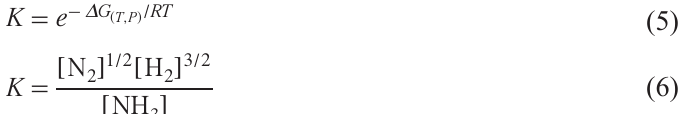
The thermodynamic equilibrium of this decomposition can be determined by minimizing the total Gibbs energy of the reaction:
The Gibbs free energy can be defined as follows:
g̅i is expressed as follows:
where, g̅0fi is the standard energy of formation at standard conditions, fi and fi0 are the species fugacity at the system conditions and at standard conditions, respectively.
An optimal condition for the cracking process involves a combination of elevated temperature and reduced pressure. By employing the equations mentioned earlier, it is possible to calculate the equilibrium compositions of the cracking reaction under different temperature and pressure conditions.
Notably, ammonia achieves complete decomposition when subjected to temperatures exceeding 500 °C under atmospheric pressure as shown in Fig. 3. However, while thermodynamically it should undergo complete decomposition within SOFC operating conditions (ranging from 600 to 900 °C), the actual extent of decomposition at the anode depends on the rate of the cracking reaction. However, a reasonable reaction rate requires the presence of catalyst even at the high operational temperature of SOFCs.[92]
![[{"id":"pzTPffxQLM","type":"paragraph","data":{"text":"Thermodynamic feasibility of ammonia decomposition. Reproduced from Ref. 92."}}]](/storage/images/resized/goGNchIW1zJVan59Kgoy56RRgKJwSmg8ro1H9Na8_xl.webp)
The elemental kinetics of ammonia decomposition reactions are mainly as follows[93]
(a) Ammonia is adsorbed on the active sites of the catalyst (equation (7)).
(b) N – H bond is successively cleaved to form H atoms (equations (8) – (10)).
(c) N and H atoms desorb from the active site to form N2 and H2 gas (equation (11), (12)).
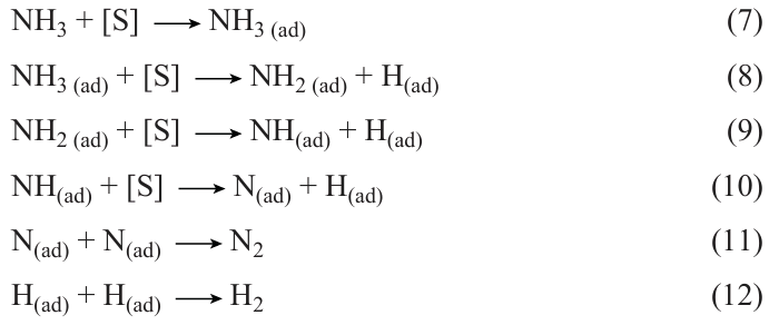
The two key steps of these elementary reactions are the adsorption of ammonia on the catalyst site and the desorption of adsorbed N-atom and H-atoms from the active site to form N2 and H2 gas mixture.[94]
To choose a suitable catalyst, one must consider a material that has sufficient binding energy to adsorb ammonia but not too strong as it makes it difficult for N-atoms to desorb.[95] In this context, the volcano relationship for the electrocatalytic hydrogen evolution reaction is illustrated in Fig. 4 for better understanding.[96] Turnover frequency (TOF) is an important indicator of the number of reaction cycles per reaction site per unit time. It allows researchers to determine the efficiency of the catalyst for a particular conversion.[97] Ruthenium has the highest TOF, which means that it is most suitable for efficient ammonia conversion. However, it is a rare metal, so researchers tend to focus on Ni or Co catalyst systems.[98][99] Therefore, catalyst design for ammonia decomposition is another issue that requires planning and calculation.
![[{"id":"y25w6ClMWm","type":"paragraph","data":{"text":" Relationship between catalyst TOF and nitrogen adsorption energy. Reproduced from work.<sup>96</sup>"}}]](/storage/images/resized/pLwdC447Wc0LHdzaFM2XyGPLO6NQB29wrmdfkqZy_xl.webp)
4. DA-SOFCs
The conventional SOFC is a solid oxide electrolyte fuel cell that uses a perovskite cathode and cermet anode materials to electrochemically oxidize hydrogen to produce electricity.[100-104] Fueling a SOFC with ammonia requires modifications to the standard anode-electrolyte-cathode configuration.[105] One way is to connect a reformer externally either inside or outside the fuel cell chamber. Another way is to either modify the anode material to allow a dual purpose or deposit a cracking layer made from an ammonia decomposition catalyst.[80][91][106] A reformer, both external and internal, incurs additional costs and energy to thermally crack ammonia first. The direct deposition of the catalyst layer on the anode side is the most common approach. Since ammonia decomposition is thermodynamically and kinetically favourable at temperatures above 700 °C, ammonia as a direct fuel for SOFCs appears to be efficient. The increased efficiency comes from two facts: the thermodynamic equilibrium composition of ammonia as low as 0.03% at 650 °C; this endothermic reaction can be easily coupled with hydrogen oxidation reaction.[91][94] Moreover, direct deposition of the catalyst layer with the anode has already been tested for other carbon-based fuels, e.g., dry ethanol or octane fuel. Both experiments showed high performance and stability; the coke formation tolerance was also satisfactory. However, the thermal expansion coefficient (TEC) mismatch can still be a problem with the catalyst layer, which is mainly metallic. The layers have a tendency of cracking or delamination.[80][91]
4.1. Microstructure evolution of anode side exposed to ammonia gas
The catalytic decomposition of ammonia over the nickel-based anode produces hydrogen which can mix with ammonia to cause a thermochemical phenomenon known as nitriding or gaseous nitriding. Industrially, nitriding is a benificial treatment applied to metallic substrates that improves mechanical properties, such as fatigue and wear resistance. When nickel metal atoms are exposed to a NH3/H2 environment at 1 atm, the nitriding potential is reasonably reduced. Ammonia acts as a nitrogen-donating medium with increased chemical activity of nitrogen, which would be significantly lower in the case of molecular nitrogen.[107] To understand the nitriding phenomenon, two hypothetical partial reactions can be arranged:[108]
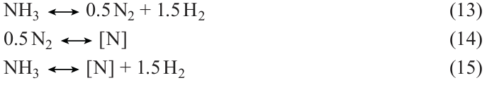
Ammonia decomposes into nitrogen and hydrogen (equation (13)). At nitriding temperatures, the equilibrium of equation (13) is completely on the right side. Nitrogen atoms dissolve in the interstitial space of solid nickel (equation (14)). Combining these two equations (equation (15)) under the assumption, that local equilibrium has been established between the gas and nickel anode surface, the following equation can be used to evaluate the hypothetical pressure of the molecular nitrogen:
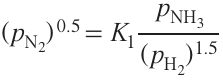
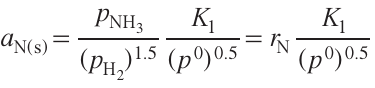
where pNH3 is the partial pressure of ammonia, pH2 is the partial pressure of hydrogen and K1 is the equilibrim constant of equation (13).
Here, the equilibrium condition between gas and solid nickel suggests that the chemical potential in the gas and the interstitials of nickel must be equal.
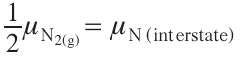
where μN2 (g) is the chemical potential of nitrogen in the gas, μN (interstate) is the chemical potential of nitrogen in the interstitials of nickel.
Using the ideal gas law,
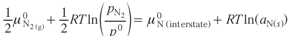
where R is the gas constant, T is the absolute temperature, pN2 is the partial pressure of nitrogen gas from equation (16), aN(s) is nitrogen at the surface of the nickel anode, μ0N2 (g)is the chemical potential of the standard pressure of gases, p0 = 1 atm, μ0N (interstate) is the standard chemical potential of the nitrogen present in the interstitials of the nickel anode.
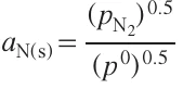
From equation (19), the activity of nitrogen can be calculated as:
Substituting equation (16) in equation (20),
where rNis the nitriding potential.
This nitriding potential can be defined as the formation ability of a nitriding atmosphere to form nitride phases at a given temperature and pressure.[109] Since nitriding is a known industrial process, various studies have been carried out on binary metal-nitrogen systems to understand the thermodynamics and kinetics of the nitride phases. Leineweber et al.[109] carefully studied nickel substrates nitrided at 1 atm. The temperature was varied from 175 to 550 °C in order to observe the growth of Ni3N layers and the resulting generation of macro stresses. This study indicates a potential degradation risk that ammonia-fueled SOFC could face. Since most SOFC anodes are nickel-based and undergo catalytic decomposition of ammonia, a suitable gaseous environment can lead to the formation of nitride phases on SOFC anodes. These nitride phases are detrimental because they induce a TEC mismatch with the nickel-based anode. Leinweber et al.[109] found that specimens nitrided at 400 °C and 500 °C showed compressive macro defects originated from the TEC mismatch during the cooling process.
Therefore, it is important to consider the microstructure evolution of nickel-based anodes under an ammonia/hydrogen gas environment. Wang et al.[105] undertook an in-depth study of the effect of ammonia fuel on Ni-YSZ cermet anode at 600 °C and 700 °C to assess how the phenomenon of nitriding affects the microstructure and performance of ammonia-fueled SOFCs. SEM images of the outer surface of the anode before and after 24 h exposure to ammonia are shown in Fig. 5a,b,c. After heat treatment at 700 °C in an ammonia atmosphere, the surface of Ni particles becomes rough with pores <100 nm. This suggests weakened Ni-YSZ contacts due to nickel nitride formation and increased ohmic resistance. Similar effects are observed at 600 °C (Fig. 5b). Moreover, Energy Dispersive X-ray (EDX) analysis (Fig. 5d) confirms the presence of nitrogen on the nickel surface. This observation was further validated by mass spectrometry results (Fig. 5e). A Ni-YSZ powder was annealed in the presence of ammonia and the outlet gas was closely monitored during the heating time. As the temperature increased, the nitrogen gas signal increased steadily, while the hydrogen and ammonia signals remained constant. This strongly suggests that nitrogen originates from the nickel nitride phase. In addition, a temperature cycling test was performed on an anode-supported cell using ammonia and hydrogen. It was clear that the nitriding process of nickel triggered a partial delamination of the support layer of the Ni/YSZ anode, ultimately resulting in severe degradation of the cell (Fig. 5f). This study concluded that process parameters are key to controlling the nitriding potential and thus preventing the degradation of ammonia-fed electrochemical cells.
![[{"id":"oLTKPSlyZG","type":"paragraph","data":{"text":"SEM image of (<i>a</i>) as-sintered anode surface (<i>b</i>) cell operated at 600 °C in ammonia for 24 h (<i>c</i>) cell operated at 700 °C in ammonia for 24 h (<i>d</i>) EDX spectra for Fig. 5<i>a,b,c</i> at star marked position. (<i>e</i>) Mass spectra of the outlet gas from Ni-YSZ powder annealed at 700 °C. (<i>f</i>) Thermal cycling of a SOFC cell and open circuit voltage (OCV) degradation over time. Reproduced from work.<sup>105</sup>"}}]](/storage/images/resized/NaWXHzOR7RLK6JDha2LXIWeehraQ1LvV0bL3Gy8J_xl.webp)
Singh et al.[110] and Wan et al.[111] provided an evidence of degradation due to Ni3N phase formed in ammonia-fed fuel cells. The comparison between anode-supported SOFC and electrolyte-supported SOFC was made with ammonia and hydrogen fuel at 700 °C. After 10 h of operation, the microstructure evolution was studied for ammonia fuel. The Ni particles coarsened significantly at the anode surface because the partial pressure of ammonia is at its maximum at the surface (Fig. 6a,b). As the gas moves towards the anode/electrolyte interface, the partial pressure of ammonia decreases and nitridation becomes less favourable. Some researchers have gone beyond the operating conditions to see if the nitride formation could be suppressed.
![[{"id":"8MfgmRTjAC","type":"paragraph","data":{"text":"Secondary electron images of (<i>a</i>) the surface and (<i>b</i>) cross-section of the cell operated at 700 °C for 24 h. Reproduced from work.<sup>110</sup>"}}]](/storage/images/resized/9sto3TGnoe6nBfwZcwEbUQPzYw0iqSYLKtBLEd11_xl.webp)
Hashinokuchi et al.[112] added chromium to a Ni/samaria doped ceria (Ni/SDC) anode to achieve greater anode stability and higher activity for ammonia cracking. The formation of nickel nitride leads to a volume change, and it is hypothesized that this nitriding phenomenon results in the agglomeration of Ni/SDC particles. At 700 °C, an anode-supported cell containing Ni/SDC was exposed to ammonia for 30 h to observe morphological changes on the outer surface of the anode. Fig. 7a,b demonstrates Ni coarsening and Fig. 7c shows the XRD results confirming the presence of nickel nitride phase. It is inevitable to conclude that the nitride phase is responsible for the deterioration of the anodes. The presence of nickel nitride is also confirmed by the Ni – N phase diagram, which indicates that a Ni3N phase is stable in pure ammonia at 700 °C. The group added Cr as a metal oxide with low surface energy to promote Ni particle connectivity by increasing the wettability of Ni particles and suppressing the agglomeration of Ni in SOFC anodes. 3 at.% Cr in Ni/SDC anode showed improved stability in ammonia at 700 °C. Accordingly, the nitriding phenomenon is critical for ammonia-fed SOFC as it leads to the inevitable degradation of SOFC anodes. Overall, durability studies of DA-SOFC may have to address the issue of nitridation at the anode side if a robust technology is expected.
![[{"id":"Maol_gzo-S","type":"paragraph","data":{"text":"Comparison of Ni particle coarsening in (<i>a</i>) Ni<sub>97</sub> – Cr<sub>3</sub> and (<i>b</i>) Ni/SDC anodes after 30 h NH<sub>3</sub> exposure (<i>c</i>) XRD spectra of NiO and NiO – NiCr<sub>2</sub>O<sub>4</sub> (Ni : Cr = 97 : 3) powders after annealing in NH<sub>3</sub> at 873 K for 10 h, indicating the presence of Ni<sub>3</sub>N phase. Reproduced from work.<sup>112</sup>"}}]](/storage/images/resized/U4YeMTUBJfPnrnSww7ZaphNky31DpbBcVuv0pRN1_xl.webp)
4.2. Progress and innovations in DA-SOFC
The history of ammonia-fueled SOFCs begins when Farr and Vayenas supplied ammonia to a ceramic oxide electrolyte fuel cell to produce nitric oxide in 1980.[113] They achieved a 60% yield; however, they also reported the production of electric power as shown in Fig. 8a. To the best of our knowledge, this was the first ever evidence of power generation from ammonia-fueled SOFCs. This cell operated at 900, 1000, 1100, and 1200 K; it showed large ohmic and polarization resistances, especially at 900 K where the voltage dropped to almost zero.[114]
![[{"id":"2HKC9rRW--","type":"paragraph","data":{"text":"(<i>a</i>) Voltage–ampere сharacteristics observed for the ceramic oxide electrolyte cell tested with ammonia as a fuel. (<i>b</i>) Voltage–ampere сharacteristics for cells operated with ammonia and hydrogen at 800, 900, and 1000 °C. Reproduced from work.<sup>114</sup> (<i>c</i>) Performance curves obtained from diluted ammonia SOFC at 750 °C. Reproduced from work.<sup>116</sup>"}}]](/storage/images/resized/EKEEhD2E3D0AoRGsiCCv8jNK4XUA9YFFpAN46oq9_xl.webp)
Since then, ammonia SOFC testing has begun. In 2003, Wojcik et al.[114] reported an ammonia-fueled SOFC that produced 84 mW cm–2 at 900 °C using yttria-stabilized zirconia (YSZ) as an electrolyte with Pt anode and no additional catalysts. This research group tested different arrangements of the anode and cathode with ammonia and hydrogen at temperatures 800, 900, and 1000 °C, respectively, as shown in Fig. 8b. The performance curves for hydrogen and ammonia were quite similar at 800 and 1000 °C which was encouraging for future researchers.
Gradually, the focus was shifted towards ammonia as a carbon-free fuel in electrochemical power generation.[115] In 2016, Cinti et al.[116] operated a SOFC stack fueled by pure and diluted ammonia. Four anode-supported cells were assembled using Crofer22APU interconnects with a total active area of 320 cm2. The theoretical and experimental work showed reasonable efficiency, and it was concluded that diluted ammonia can be considered as a potential fuel, since it is neither toxic nor flammable, as shown in Fig. 8c.
According to Fig. 9a, Miyazaki et al.[115] used a Ni – Ba(Zr,Y)O3 (Ni-BZY) cermet anode instead of the conventional Ni-YSZ, which shows complete decomposition of ammonia only at temperature >600 °C. Ni-BZY was highly resistant to hydrogen poisoning at 650 °C and achieved approximately 100 mW cm–2. Hydrogen poisoning is an effect that is observed at high hydrogen partial pressure at the anode side during ammonia decomposition. In such a condition, excess hydrogen atoms cover the active sites of the anode surface and reduce the dissociative adsorption of nitrogen on the catalyst surface. Consequently, the activity of anode catalyst is suppressed.
![[{"id":"9LaY3xhNpb","type":"paragraph","data":{"text":"(<i>a</i>) Voltage–ampere сharacteristics for the direct ammonia SOFC with Ni-Ba(Zr,Y)O<sub>3</sub> cermet. Reproduced from work.<sup>115</sup> (<i>b</i>) Effect of pressurization on power density at 750 °C. Reproduced from work.<sup>117</sup> Comparison of the Voltage – Current density – Power density curves of the PCFC run by Aoki et al.<sup>118</sup> using (<i>c</i>) ammonia and (<i>d</i>) hydrogen as a fuel. Reproduced from work.<sup>118</sup> (<i>e</i>) Comparison of the Voltage – Current density – Power density curves of the PCFC run on 12 different fuels by Duan et al.<sup>119</sup> (<i>f</i>) Peak power densities of 12 fuels with degradation rates for selected fuels. Reproduced from work.<sup>119</sup> (<i>g</i>) Effect of Ni content of a Ni-impregnated SDC anode on catalytic activity. Reproduced from work.<sup>123</sup> (<i>h</i>) Voltage–ampere сharacteristics for ammonia SOFC and 75 vol.% H<sub>2</sub> SOFC. Reproduced from work .<sup>120</sup>"}}]](/storage/images/resized/1q2FifQFTomqNSUhd3ylkbQh9ZF0vZ2dV0RdvZ6H_xl.webp)
In addition, Shy et al.[117] experimented with pressurized ammonia as a fuel for SOFC (Fig. 9b)[118-120]. Their impedance analysis showed a large resistance attributed to gas diffusion. Increasing the pressure (up to 3 atm) and temperature seemed to reduce the gas diffusion resistance. Thus, cell performance with ammonia increased and came close to that of hydrogen-fueled SOFCs.
Recently, there have been notable advances in the field of protonic ceramic fuel cells (PCFCs).[121][122] Aoki et al.[118] conducted a study that demonstrated an impressive increase in power density using ammonia as a fuel source. They achieved this by developing a cell with a 1 mm-thick BaZr0.1Ce0.7Y0.2O3-δ (BZCY) thin-film electrolyte deposited on a Pd solid anode. Performance analyses were performed over a temperature range of 450 – 600 °C, and the results were compared with those obtained using hydrogen fuel (as shown in Fig. 9c,d ). At 600 °C, the PCFC generated a peak power density of 580 mW cm–2 using ammonia fuel. Furthermore, Duan et al.[119] investigated a total of 12 different fuels for PCFC, including ammonia. Their results showed that ammonia emerged as a strong contender as a SOFC fuel, second only to hydrogen. In particular, they observed a power density of 600 mW cm–2 at 600 °C (Fig. 9e, f ), which is a further confirmation of the results obtained by Aoki et al.[118]
Itagaki et al.[123] tested SDC anodes electrophoretically deposited with nickel. A mixture of 6% ammonia/argon gas was used as a fuel for the electrochemical tests. The as-impregnated Ni significantly improved the catalytic activity of SDC over the conventional anode. The best catalytic activity was achieved at 10 wt.% Ni (Fig. 9g), as a decrease the Ni content resulted in a decrease in the molecular diffusion resistance. A maximum power density of 99 mW cm–2 was obtained at 900 °C (Fig. 9h). Furthermore, Stoeckl et al.[120] operated a SOFC with a conventional anode material to compare pure ammonia supply with a 3 : 1 hydrogen to nitrogen fuel mixture. The OCV values went up to 1.26 V at 700 °C, and a direct ammonia supply can result in even higher OCV values. The two fuels provided similar I – V graphs and impedance plots suggesting that ammonia is a prime candidate for SOFCs as an alternative fuel.
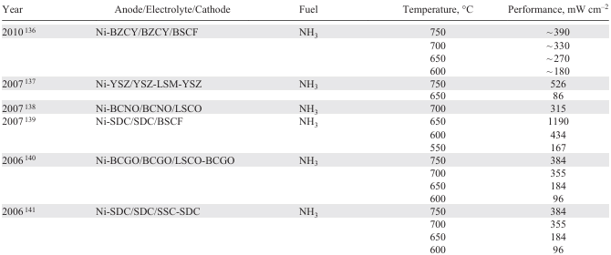
Especially in the last few years (2020 – 2022), the focus on direct ammonia fuel cells has increased, Table 1[124-141]. Researchers have historically tested conventional Ni-YSZ anodes for ammonia decomposition, but novel materials have recently surfaced in the literature. Song et al.[121] used La0.55Sr0.30TiO3−δ (LST) perovskite substrates infiltrated with NiCo alloy nanoparticles and deposited them on an SDC anode scaffold to construct an electrolyte-supported cell. At 800 °C, such a cell produced a peak power density of 361 mW cm–2. The LSTNC-infiltrated SDC anode with ammonia recorded a low ohmic resistance which was extremely close to the hydrogen counterpart (Fig. 10). It also withstood degradation for 120 h when operated at 700 °C.

![[{"id":"VpZaXSwB_O","type":"paragraph","data":{"text":"Voltage–Current density–Power density curves for (<i>a</i>) H<sub>2</sub> fueled SOFC, (<i>b</i>) NH<sub>3</sub> fueled SOFC. Impedance graphs for (<i>c</i>) H<sub>2</sub> fueled SOFC, (<i>d</i>) NH<sub>3</sub> fueled SOFC. Reproduced from work.<sup>121</sup>"}}]](/storage/images/resized/ksZ45obO7xyxrfeYsdgQiOyb5ZABDrHYcKRyQLiV_xl.webp)
Xu et al.[122] carried out a study showing the improvement of a typical Ni-YSZ anode through the incorporation of CeO2 – δ nanoparticles (NPs). They fabricated a conventional SOFC with a YSZ/GDC bilayer and a PrBa0.8Ca0.2Co2O6 – δ (PBCC) cathode. In some cells, they applied a surface coating of CeO2 – δ NPs on the anode side using an infiltration technique.[123] These cells were subjected to testing with pure H2 and NH3 , covering a temperature range of 700 to 800 °C. The electrochemical characterization of the cells revealed that the ceria NP infiltration led to an increase in peak power density for both fuels. Notably, the highest peak power density value (2144 mW cm–2) was achieved with H2 at 800 °C (Fig. 11a,b).[122] Of particular significance was the effect of ceria loading on ammonia fuel with a remarkable 37.7% increase in peak power density. In contrast, the hydrogen-fed SOFC demonstrated a slightly lower gain of 34.5%. To benchmark their findings, the group compared their work with peak power density data reported in the literature spanning from 2006 to 2022, and their cell surpassed all previous records (Fig. 11c).[123]
![[{"id":"5bIZe3Aaic","type":"paragraph","data":{"text":"Anode Voltage–Ampere сharacteristics in the presence of H<sub>2</sub> and NH<sub>3</sub> for (<i>a</i>) Ni-YSZ and (<i>b</i>) Ni-YSZ with infiltrated CeO NPs. (<i>c</i>) Comparison of DA-SOFC (Ni-YSZ with infiltrated CeO NPs) with data reported in the literature from 2006 to 2022. Reproduced from work.<sup>122</sup> (<i>d</i>) Electrochemical performance of tubular PCFC with NH<sub>3</sub> fuel in the temperature range of 650 °C to 750 °C. Reproduced from work.<sup>124</sup> (<i>e</i>) Comparison of the electrochemical characteristics of tubular PCFC with pure H<sub>2</sub> , 3H<sub>2</sub> : 1N<sub>2</sub> , and pure NH<sub>3</sub> . Reproduced from work.<sup>125</sup> *Reference numbers from work <sup>125</sup> are indicated."}}]](/storage/images/resized/662PGPmz1DutLCVVsiSAV5IKF9yNe6ynXVPtQ3Vz_xl.webp)
Nowicki et al.[124] evaluated the performance of a ammonia-fueled tubular PCFC, specifically for maritime applications. They utilized a NiO/BaCe0.7Zr0.1Y0.16Zn0.04O3 – δ (NiO/BCZYZ) tubular support, which was dip-coated with BCZYZ electrolyte and a La0.8Sr0.2Co0.5Fe0.5O3 – δ /BaCe0.7Zr0.1Y0.16Zn0.04O3−δ (LSCF/BCZYZ) oxygen electrode, providing an active area of 36 cm2. A comprehensive analysis using detailed electrochemical impedance spectroscopy was carried out to investigate the contributions of the different processes, including H2 protonation, gas diffusion, and ohmic losses. The performance analysis demonstrated that the tubular PCFC achieved a peak power of 236 mW cm–2 at 750 °C and a flow rate of 133 ml/min of NH3 (Fig. 11d). To gain a deeper understanding of the heat management in ammonia-driven SOFCs, Jantakananuruk et al.[125] conducted experiments using tubular SOFCs with pure H2 , 3 H2 : 1N2 , and pure NH3 at three different temperatures: 700, 800, and 900 °C. Surprisingly, all three fuels generated the same peak power density at temperatures above 700 °C, despite slight variations in fuel utilization (Fig. 11e). The researchers emphasized the need for heat analysis due to the endothermic decomposition of ammonia, which is critical to achieving stable heat integration. In conclusion, it was revealed that at temperatures exceeding 700 °C, the temperature gradient converged to zero, indicating complete ammonia decomposition and effective utilization. This finding highlights the importance of proper heat management to maximize the performance of ammonia-driven SOFCs.
Chien et al.[142] investigated the utilization of PCFC with ammonia fuel. Their study aimed to compare the performance of PCFCs and conventional SOFCs both with and without a lanthanum strontium ruthenium titanate (LSRT) catalyst on the anode side. In the experiment, the electrolyte-supported cells were exposed to pure hydrogen and ammonia at a temperature of 600 °C. Initially, the SOFC exhibited better performance (23.1 mW cm–2 with 1% LSRT) with both fuels (Fig. 12).[142] However, it experienced rapid degradation within a mere 24 h despite the stable nature of the PCFC. The observed stability for the latter is attributed to the oxidation process occurring at the cathode side, whereas in the case of the SOFC, repetitive nitridation and subsequent oxidation at the anode side lead to structural degradation.
![[{"id":"l6QWvljxda","type":"paragraph","data":{"text":"Comparison of the Voltag–Current density–Power density curves for SOFCs based on NiO/YSZ (<i>a, b</i>) and NiO/BZCY (<i>c, d</i>) with and without LSTR doping fueled hydrogen (<i>a, c</i>) and ammonia (<i>b, d</i>). Reproduced from work.<sup>142</sup>"}}]](/storage/images/resized/05enLC2GIn5fQZpzy4wZouAUkNDnMIoeGEeVlQB0_xl.webp)
Wang et al.[133] modified the conventional Ni-YSZ into Ba – Ni-YSZ to enhance the catalytic activity of the anode at low temperatures. The issue of hydrogen poisoning was mitigated when these anodes were introduced in a flat-tubular SOFC with symmetrical double-sided cathodes (DSC). In another literature report, Wang et al.[143] performed 15 thermal cycles and found promising stability of flat-tubular DSC cells (Fig. 13a).
![[{"id":"t3J50pRH1T","type":"paragraph","data":{"text":"(<i>a</i>) Thermal cycling of flat tubular DSC cells from 550 °C to 750 °C. Reproduced from work.<sup>143 </sup>Electrochemical performance of protonic SOFC for (<i>b</i>) H<sub>2</sub> and (<i>c</i>) NH<sub>3</sub>. Reproduced from work.<sup>131</sup> (<i>d</i>) Comparison of the kinetic activity of r-PSCF and r-PSCFRu. Reproduced from work.<sup>127</sup> Electrochemical Performance of (<i>e</i>) bare tubular protonic SOFC and (<i>f</i>) Fe embedded protonic SOFC. Reproduced from work.<sup>128</sup> (<i>g</i>) Effect of Fe infiltration on the performance of NH<sub>3</sub>-PCFC. Reproduced from work.<sup>129</sup>"}}]](/storage/images/resized/L7vp5pJo4s5w8Va7FlFracuJRf97FbxRYPoH7GTP_xl.webp)
Miyazaki et al.[144] investigated PCFC for ammonia supply and experimented with Ni – BaCe0.4Zr0.4Y0.2O3 – δ cermet anode to perform the impedance analysis with ammonia fuel. Ammonia fuel supply conditions were found to strongly affect the mass transfer in fuel cells and thus the polarization resistance. Recently, Zhu et al.[131] suggested Ru – (BaO)2(CaO)(Al2O3) (Ru-B2CA) as a reversible ammonia catalyst for reversible PCFC. In both operation modes, the group reported reasonable results. At 600 °C, the cell was operated for 1250 h under stable conditions. It generated 877 mW cm–2 at 650 °C (Fig. 13b,c).
In the last two years (2022 – 2023), researchers have proposed various novel compositions and modifications for materials to combat sintering problems of anodes for ammonia.[145][146][147] A Pr0.6Sr0.4Co0.2Fe0.75Ru0.05O3 – δ composite anode recently prepared by Xiong et al.,[127] is characterized by an increased kinetic activity of the anode materials and a significant avoidance of sintering problems as depicted in Fig. 13d. Pan et al.[128] experimented with a tubular protonic SOFC with an embedded catalytic iron layer. Peak power density of around 1060 mW cm–2 was achieved (Fig. 13e, f ) by minimising anode contact with ammonia which enhanced the activity and durability of the cell. Zhang et al.[129] fabricated a Fe-decorated Ni-BaZr0.1Ce0.7Y0.1Yb0.1O3 (Ni–BZCYY) anode and verified its kinetics using first principles-based mechanistic and microkinetic modelling. A peak power density of 1609 mW cm–2 at 650 °C was observed (Fig. 13g).
In summary, since the first demonstration of electricity generation from ammonia-fueled SOFCs in 1980, there has been a steady increase in the number of new ammonia-fueled SOFCs. Over the years, researchers have tested various anode and cathode arrangements with ammonia and hydrogen at different temperatures. As discussed, researchers have explored new materials and their modifications to overcome the problems of anodes for electrochemical ammonia synthesis. These include infiltrating NiCo alloy nanoparticles on perovskite substrates, modifying conventional Ni-YSZ into Ba – Ni-YSZ, and using PCFCs instead of the conventional SOFCs based on oxygen-conducting electrolytes. The latest report suggests Ru – (BaO)2(CaO)(Al2O3) (Ru-B2CA) as a potential ammonia catalyst for reversible PCFC. Among these reports, many researchers have achieved performance curves close to those of the conventional hydrogen SOFCs making the topic of direct ammonia SOFCs particularly attractive.
5. Conclusion
Ammonia is one of many fuel sources for producing clean energy that is as environmentally friendly as hydrogen and has no net carbon emissions. It is also easy to store and distribute. Because of its nature, ammonia can be stored in liquid form under favourable conditions. Over the last past decade, numerous studies have been conducted on ammonia, supporting the claim that it is the best carbon-free energy source. Since the high operating temperature (>600 °C) could contribute to in-situ ammonia decomposition in the presence of catalysts, ceramic fuel cells have been used for direct ammonia utilization. SOFCs have the potential to be one of the most competitive energy conversion technologies due to their inherent high efficiency and minimal pollutant emissions. Very high operating temperatures make SOFC a fuel-flexible technology, allowing the use of alternative fuels such as ammonia. Some recent works have reported that the NH3-fed SOFC or PCFC performances are comparable to those of the hydrogen-fueled counterparts, but several degradation issues need to be addressed before stable, industrial-scale operation can be achieved.
Acknowledgment
Dr. D.Medvedev thanks to the Russian Science Foundation (Project No. 21-73-10004) for suppot of his research activities.. Dr. M.H. Hanif and Dr. M. Motola thank to the Scientific Grant Agency of the Slovak Ministry of Education, Sciences, Research and Sport (VEGA) # 1/0319/23, Grant of the Comenius University Bratislava for Young Scientists (UK/24/2023), Operation Program of Integrated Infrastructure for the project, UpScale of Comenius University Capacities and Competence in Research, Development and Innovation, ITMS2014+: 313021BUZ3, co-financed by the European Regional Development Fund, and European Regional Development Fund.
6. List of abbreviations
Abbreviations:
CHP — Combined Heat And Power.
DA-SOFC — Direct Ammonia Solid Oxide Fuel Cell.
DSC — Doubled Sided Cathodes.
EDX — Energy Dispersive X-ray.
NP — Nanoparticles.
OCV — Open Circuit Voltage.
ORR — Oxygen Reduction Reaction.
PCFC — Protonic Ceramic Fuel Cells.
SOFC — Solid Oxide Fuel Cell.
TEC — Thermal Expansion Coefficient.
Composition designations:
B2CA — (BaO)2(CaO)(Al2O3),
BCFZY — BaCo0.4Fe0.4Zr0.1Y0.1O3−δ,
BCGO — BaCe0.8Gd0.2O2.9,
BCNO — BaCe0.9Nd0.1O3−δ,
BCY20 — BaCe0.8Y0.2O3−δ,
BCYZY — BaCe0.7Zr0.1Y0.16Zn0.04O3−δ,
BCZY — BaCe0.4Zr0.4Y0.2O3−δ,
BSCF — Ba0.5Sr0.5Co0.8Fe0.2O3−δ,
BZY — Yttrium-doped Barium Zirconate,
BZY20 — BaZr0.8Y0.2O3–δ,
BZCY — BaZr0.1Ce0.7Y0.2O3-δ,
BZCYYb — BaZr0.1Ce0.7Y0.1Yb0.1O3−δ,
GDC — Galdonia-doped Ceria,
LSCF — Strontium-doped Lanthanum Cobalt Ferrite,
LSCO — Stronitum-doped Lanthanum Cobaltite,
LSGM — Mg-doped Lanthanum Gallate,
LSM — Strontium-doped Lanthanum Manganite,
LST — La0.55Sr0.30TiO3−δ,
LSTR — La0.4Sr0.6Ti0.98Ru0.02O3,
PBCC — PrBa0.8Ca0.2Co2O6−δ,
PBSCF — PrBa0.5Sr0.5Co1.5Fe0.5O5+δ,
PSCFRu — Pr0.6Sr0.4Co0.2Fe0.75Ru0.05O3-δ,
SDC — Samaria-doped Ceria,
SSC — Sm0.5Sr0.5CoO3−δ,
YSZ — Yttria-stabilized Zirconia.
References