Keywords
Abstract
Currently, the main type of electrochemical energy storage devices are lithium-ion batteries, the global production of which amounts to billions of units per year. Further progress in electrochemical energy storage systems may follow two general trends: improvement of existing lithium-ion batteries and design of alternative types of energy storage devices (so-called post-lithium-ion batteries). The former trend is limited by the fact that characteristics of lithium-ion batteries are approaching the theoretical limit. The latter one is concerned with sodium-ion batteries, lithium–air batteries and primary power sources, lithium–sulfur batteries, and redox flow systems. The present review analyzes state-of-the-art in the development of virtually all types of electrochemical energy storage devices, which makes it possible to compare their characteristics and determine the most appropriate applications for each type of device.
The bibliography includes 316 references.
1. Introduction
The role of energy storage systems has been steadily growing in recent years due to the development of renewable energy sources (green energy), smart grids, and wireless electric vehicles, as well as portable electronic devices and power tools. The use of large electrical energy storage systems ensures the reliability of electrical grids, lower electricity costs for most consumers, and sharp decrease in greenhouse gas emissions. In many cases, energy storage systems provide for the uninterrupted operation of critically important facilities, e.g., health care facilities. Small-capacity storage devices serve for mobile communication and navigation, which are essential for modern life.
A highly important type of energy storage systems are electrochemical energy storage batteries. The awarding of the 2019 Nobel Prize in chemistry for the development of lithium-ion batteries clearly demonstrates their importance to modern civilization. It is the development and wide-scale manufacturing of lithium-ion batteries that made cell phones an indispensable part of everyone’s life. Currently, lithium-ion batteries are the only power sources for all portable devices with no alternative. The energy density of lithium-ion batteries exceeds that of all other types of batteries, including silver – zinc batteries. As compared with the most widely used lead-acid batteries, lithium-ion batteries have 6 – 8 times higher specific capacity.
The production of lithium-ion batteries was first commenced in 1990 by Sony (Japan). The global market for lithium-ion batteries grew from $ 5 billion in 2006 up to $ 20 billion in 2016 and up to $ 5 billion in 2022. It is projected to reach $ 193 billion by 2028.[1] The success of lithium-ion batteries is determined not only by their high energy density, but also by other performance characteristics such as wide operating temperature range, low self-discharge (i.e., good charge retention), good cycle life, the ability to withstand rapid charge and discharge, and the possibility of replacing commercial electrochemical systems based on graphite and lithium cobaltate by new electrochemical systems.[2]
Throughout their history, lithium-ion batteries have been continuously improved, and their further development is underway on a large scale. However, the fundamental limitations inherent in lithium-ion batteries (related to raw materials, reliability, and safety) have led to the emergence of new types of batteries belonging to the so-called post-lithium-ion era. They include sodium-ion, lithium – oxygen (lithium – air), and lithium – sulfur batteries and also redox flow systems.[3]
Lithium–air batteries (LABs) represent a new generation of lithium power generators that are superior to most known chemical power sources in the theoretical energy density. The specific capacity of lithium metal amounts to 3860 mA h g–1, which is almost two times higher than that of zinc and 30% higher than that of aluminium.[4] Enhanced weight and size characteristics of LABs are also promoted by high oxidative power of oxygen and the possibility of using oxidation with atmospheric oxygen, which can enter the system via natural convection from the external environment. Despite the increased interest in LABs over the past 10 – 15 years, the research into these energy storage devices is not sufficiently active, which is attributable to challenges faced in the design of Li – O2 system components and optimization of their operating conditions.
The major application of redox flow batteries is currently for stationary electrical energy storage systems. The renewable energy production, particularly wind and solar power generation, markedly depend not only on the season and time of day, but also on the weather. As the proportion of electricity generated from rebewable sources increases, the uncertainty concerning energy generation in power grids grows. This issue should be addressed by envisaging excess capacity in conventional power generation, long-distance power transmission, and the deployment of energy storage systems. Currently, China is recognized as the leader in renewable energy production. In 2023, the electrical energy gained from renewable sources in China accounted for 32% of the global renewable power generation; this proportion for USA is 11%; that for Brazil is 7.0%, that for Canada is 4.7%, and that for India is 4.3%.a In China, the proportion of renewable electrical energy in 2024 was 35% of the total generated electrical energy.b The leading role of China in renewable energy generation has led to its superiority in the development of energy storage systems. In 2023, the proportion of pumped hydro storage systems in China was for the first time inferior to the total contribution of all other types of energy storage systems.c In the same 2023, lithium-ion batteries accounted for almost half of the energy storage capacity in China. Redox flow batteries accounted for only 0.25% of the total installed energy storage capacity. The global energy storage market is rapidly growing. In 2024, it amounted to $ 8.9 billion; according to forecasts, the market is expected to grow up to $ 204.8 billion by 2033.d The structure of the market also changes. The proportion of energy storage systems in flow batteries, the total capacity of which in China in 2023 was 200 times lower than that of lithium-ion batteries, is projected to increase by a large factor.
Currently, there are comprehensive reviews available devoted to particular types of energy storage devices (such as lithium-ion batteries, supercapacitors, lithium – air batteries, etc.). This review presents information on the state-of-the-art for virtually all types of electrochemical storage devices, Which makes it possible to compare their characteristics and identify the most suitable applications for each type.
a https://en.wikipedia.org/wiki/List_of_countries_by_renewable_electricity_production#Renewable_production_(percent).
b State Council. The People’s Republic of China; https://english.www.gov.cn/archive/statistics/202501/28/content_WS6798de96c6d0868f4e8ef410.html
c CNESA. China Energy Storage Alliance; Energy Storage Industry W hite Paper 2025 (Summary Version); https://en.cnesa.org/
d https://www.globenewswire.com/news-release/2025/01/27/3015816/0/en/Energy-Storage-Market-Is-Expected-To-Reach-Revenue-Of-USD-204-8-Bn-By-2033-At-14-8-CAGR-Dimension-Market-Research.html.
2. Prospects for the development of lithium – ion batteries
Today, upgrading of lithium-ion batteries is mainly aimed at increasing their economic and performance characteristics, e.g., expansion of the temperature range of charging (especially toward lower temperatures),[5] increase in the charging rate (this is especially important for electric vehicles),[6] increase in the energy density by increasing the operating voltage,[7] etc. Most often, this is achieved by development of new electrode materials,[8][9] with particular attention being paid to nanomaterials.[10]
Among the negative electrode materials for lithium-ion batteries, particular attention is attracted by silicon,[11][12] Which has a record-high theoretical capacity for reversible lithium insertion (4200 mA h g–1 at temperatures above 400°С and 3600 mA h g–1 at room temperature. This is almost an order of magnitude higher that the theoretical specific capacity of graphite amounting to 372 mA h g–1). However, silicon, like all high-capacity materials, is susceptible to degradation during cyclic lithium insertion and extraction, and the efforts of researchers are focused on addressing this issue, first of all, by using nanomaterials.
The first successful studies on the use of silicon in lithium-ion batteries date back to the late 20th century and early 21st century.[13-17] In Russia, these works were started in 2005[18-22] and were devoted to lithium insertion into thin films of amorphous silicon. It was found that these films can reversibly absorb a large amount of lithium, namely, more than three lithium atoms per silicon atom. However, it was clear that electrodes that represent thin (less than 100 nm thick) silicon films on relatively thick (tens of micrometres) substrates have no practical value. Therefore, the subsequent studies were aimed at increasing the thickness of the active part of silicon electrodes. Certain success was achieved by deposition of layered two- and three-component silicon composites with other materials such as carbon, aluminium, and silicon oxides[23-30] (Fig. 1), two-component fibre composites,[31][32] and nanoporous silicon with a regular structure.[33] Electrodes with a few micrometre-thick active layer capable of withstanding more than 200 charge – discharge cycles have been reported.[30][33]
![[{"id":"-P909XUAjG","type":"paragraph","data":{"text":"(<i>a</i>) SEM image of a nanocomposite anode composed of alternating silicon and silica layers.<sup>26</sup> (<i>b</i>) SEM image of the Si – O – Al composite film on a titanium foil. The light bands correspond to layers enriched in aluminium, while the dark bands are layers depleted in aluminium;<sup>30</sup> (<i>c</i>) charge – discharge curves and (<i>d</i>) change in the discharge capacity of the Si – O – Al composite film.<sup>28</sup>"}}]](/storage/images/resized/02gzxdAolYnGvzTVLKX8835r6uHLGGTLCoNxCL8N_xl.webp)
In recent years, the interest in germanium as an alternative to silicon in lithium-ion batteries has sharply increased.[34-36] The applicability of germanium as a negative electrode in lithium-ion batteries was first reported in 2004.[37] Lithium and germanium can form intermetallic compounds with compositions ranging from LiGe to Li22Ge5 . The latter compound corresponds to a specific capacity of germanium for lithium insertion equal to 1624 mA h g–1. For the most studied composition Li15Ge4 , the theoretical specific capacity is 1384 mA h g–1. This value is more than two times lower for germanium than for silicon; however, in terms of the volumetric specific capacity, the difference between germanium and silicon is much less pronounced. The volumetric specific capacity of germanium and silicon for lithium insertion is 7366 mA h cm–3 for Li15Ge4 and 8334 mA h cm–3 for Li15Si4.
Germanium has a number of performance advantages over silicon. Owing to the fact that the band gap of germanium (~ 0.6 eV) is markedly smaller than that of silicon (1.12 eV), germanium has much higher electronic conductivity than silicon.[38] The diffusion coefficient of lithium in germanium at room temperature is 2.5 orders of magnitude higher than that of lithium in silicon,[39][40] and, what is most important, the diffusion coefficient of lithium in germanium is virtually independent of the degree of lithiation, whereas that in silicon changes by five orders of magnitude upon transition from Li0.15Si to Li3.75Si.[40] Like silicon, germanium markedly increases in volume upon lithium insertion. An important advantage of germanium over silicon is that germanium expansion upon lithiation is isotropic, whereas the expansion of silicon is anisotropic;[41][42] therefore, the degree of germanium degradation is much lower. To date, numerous germanium nanostructures have been proposed for use in the negative electrodes of lithium-ion batteries, including nanoparticles, nanofibres, nanotubes, thin films, and nanoporous electrodes, with particular attention being paid to nanofibrous structures. Previously, these structures were deposited from the gas phase by various high-temperature methods; however, relatively recently, it was shown that germanium filament nanocrystals can be produced from aqueous solutions of GeO2 via an electrochemical process using low-melting metals such as Hg or Ga as crystallization centres for germanium.[43-45] On the one hand, the liquid metal serves as an electrode for the reduction of germanium ions to atomic germanium preventing contact with water; on the other hand, it acts as a solvent in which germanium atoms generate supersaturation for crystallization. As a result, germanium is deposited at the liquid metal – substrate interface in a manner analogous to the growth of whiskers from the gas phase. This approach was successfully advanced by replacement of the liquid-metal seed by nanoparticles of a low-melting metal that is solid at room temperature such as indium.[46] Germanium filamentary nanostructures grown on indium crystallization centres are capable of reversible lithium insertion with a capacity of up to 1800 mA h g–1.[47] Electrodes with these nanofilaments retained high capacity in up to 24 C current rates (complete charging in 2.5 min) and could operate at temperatures from ‒55 to +20°С.[48][49] It is noteworthy that electrodes made of germanium nanofilaments were capable of reversible operation in electrolytes based on propylene carbonate, which is impossible for the currently used graphite-based electrodes. It was shown that the addition of minor amounts of vinylene carbonate into a propylene carbonate electrolyte gives rise to a solid electrolyte interphase (SEI) on the germanium surface and, as a consequence, leads to a sharp decrease in the electrode degradation during cycling.[50] The studies on the reversible lithium insertion into filamentary germanium nanostructures resulted in the development of a fundamentally new electrochemical system for lithium-ion batteries, in which an array of germanium nanowires on a titanium substrate was used as the negative electrode, a mixed layered oxide LiNi0.8Co0.15Al0.05O2, served as the active material of the positive electrode, and a solution of LiClO4 in a mixture of propylene carbonate and dimethoxyethane was the electrolyte.[51] Laboratory prototypes of a battery with this electrochemical system had an energy density (per unit mass of active compounds) of 400 mA h g–1 at a 1C current rate and operated at temperatures between –55 and +20°C (Fig. 2).
![[{"id":"Ja8g-RBjQJ","type":"paragraph","data":{"text":"(<i>a</i>) Diagram of operation of the NCA – Ge electrochemical system in a lithium-ion battery; (<i>b</i>) effect of temperature on the discharge capacity of the battery.<sup>51</sup>"}}]](/storage/images/resized/djCzpVx1MRD8tEbRdBRzLQl5Nakcm5oUTl6BRwI2_xl.webp)
The further development of electrodes based on filamentary germanium nanostructures was aimed at the fabrication of analogous nanostructures from germanium alloys and compounds. Among the germanium compounds used in the negative electrodes of lithium-ion batteries, phosphides are of particular interest.[46] Thus, Kulova et al.[52] proposed an original method for the synthesis of germanium phosphide nanorods based on germanium nanowires obtained by deposition from an aqueous electrolyte. The method is based on evaporation and condensation of red phosphorus in a tube with germanium nanowires. The germanium phosphide nanorods prepared in this way exhibited a reversible lithium-ion capacity of 1900 mA h g−1 at low currents and up to 500 mA h g−1 at 6.4 C rate (full charge in 9 min) (Fig. 3).
![[{"id":"5c_LDB0jbS","type":"paragraph","data":{"text":"(<i>a</i>) Schematic picture of GeP synthesis. (<i>b</i>) SEM image of the synthesized germanium phosphide nanorods. (<i>c</i>) X-ray diffraction spectra of a GeP sample on a titanium substrate. (<i>d</i>) Charge – discharge curves and (<i>e</i>) variation of the discharge capacity of germanium phosphide upon lithium insertion.<sup>52</sup>"}}]](/storage/images/resized/qquDhEdNdV2vtJFmimu8DSkBfpYjIZiW9ihl6aAZ_xl.webp)
Among germanium alloys, those containing low (a few percent) contents of cobalt hold promise. Nanostructured Ge – Co – In alloys containing both globular nanoparticles and nanowires operating over a wide temperature range at up to 16 C rates have been reported.[53-55] Also, Kulova et al.[56] described germanium cobalt phosphide nanostructures CoGe2P0.1 (or CoGe2@GeP), which can be cycled for a long time without degradation.
A particular place among active materials for negative electrodes in lithium-ion batteries belongs to lithium nanotitanate Li4Ti5O12. This material has a very high structural stability on cycling (lithium insertion and extraction) and the ability to operate under forced conditions. These characteristics are maintained if the cathodic reduction of lithium titanate during charging is limited to a final potential of 0.1 V vs. lithium electrode. The reduction product is Li7Ti5O12, and the corresponding specific capacity is 175 mA h g–1. Conversely, a higher degree of reduction, e.g., up to the composition Li9Ti5O12, with the specific capacity increasing to 292 mA h g–1, induces irreversible structural changes. However, doping of lithium titanate with iron[57] or gallium[58][59] cations makes it possible to maintain structural stability upon high degrees of lithiation. Thus, samples with the initial composition Li4.2Ti4.8Ga0.2O12 have a long cycle life in the potential range from 0.01 to 3 V and a capacity of 236 mA h g–1 at a current density of 20 mA g–1 or 85 mA h g–1 at a current density of 3200 mA g–1, which corresponds to full charge in 3 min (Fig. 4).
![[{"id":"DZSgxcVZuO","type":"paragraph","data":{"text":"(<i>a</i>) SEM image of Li<sub>3.624</sub>Ti<sub>4.944</sub>Ga<sub>0.2</sub>O<sub>12</sub>. (<i>b</i>) Charge – discharge curves of the Li<sub>3.624</sub>Ti<sub>4.944</sub>Ga<sub>0.2</sub>O<sub>12</sub> electrode at various current densities (mA g<sup>–1</sup>). (<i>c</i>) Change in the discharge capacity of Li<sub>4</sub>Ti<sub>5</sub>O<sub>12</sub> (1) and Li<sub>3.624</sub>Ti<sub>4.944</sub>Ga<sub>0.2</sub>O<sub>12</sub> (2) at various current densities (mA g<sup>–1</sup>).<sup>59</sup>"}}]](/storage/images/resized/T9yfJW5di2Sob5utI71EXgC5Yp8ltr3KSXUbO36t_xl.webp)
Doping of lithium titanate with rare earth elements is of particular interest. The relationship between the discharge capacity and the dopant concentration was established for doping with europium,[60] neodymium,[61] and erbium.[62] The dependence had a sharp maximum corresponding to the optimal dopant content (1.6% for europium, 0.75% for neodymium, and 2% for erbium).
A noticeable increase in the specific performance characteristics of lithium titanate-based electrodes (the ability to preserve high capacity at high current densities) was achieved by using nanoparticles with characteristic dimensions of 4 – 5 nm,[63] and by fabrication of composites based on anatase,[64] silver,[65] and polyaniline[66] nanoparticles. Special mention should be made of lithium titanate composites with carbon, because their characteristics considerably depend on the carbon production method and source. As a rule, carbon is produced by carbonization of organic compounds; in some cases, each particle of lithium titanate is coated with a layer of carbon, while in other cases, carbon is deposited as separate particles comparable in size to the lithium titanate particles.[67]
Thus the use of sucrose as a source of carbon to obtain the Li4Ti5O12/Csucrose composite results in the formation of highly conductive carbon coating (Fig. 5a,b).[67] If polyvinylidene difluoride (PVDF) is used to produce the Li4Ti5O12/CPVDF composite, surface fluorination of Li4Ti5O12 takes place. This results in improved electrochemical properties of the composite. Electrodes made of non-modified Li4Ti5O12 and the Li4Ti5O12/CPVDF and Li4Ti5O12/Csucrose composites have discharge capacities of 142.5, 154.3, and 170.4 mA h g–1, respectively, in the potential range of 1 – 3 V at a current density of 20 mA g–1 and discharge capacities of 57.2, 82.1, and 89.3 mA h g–1, respectively, at a current density of 3200 mA g–1 (Fig. 5c).
![[{"id":"kx_7XxUmN7","type":"paragraph","data":{"text":"(<i>a</i>) SEM image of Li<sub>4</sub>Ti<sub>5</sub>O<sub>12</sub>/C<sub>sucrose</sub>. (<i>b</i>) Charge–discharge curves for the electrode based on Li<sub>4</sub>Ti<sub>5</sub>O<sub>12</sub>/C<sub>sucrose</sub> at various current densities (mA g<sup>–1</sup>). (<i>c</i>) Change in the discharge capacity of electrodes based on Li<sub>4</sub>Ti<sub>5</sub>O<sub>12</sub> (1), Li<sub>4</sub>Ti<sub>5</sub>O<sub>12</sub>/C<sub>PVDF</sub> (2), and Li<sub>4</sub>Ti<sub>5</sub>O<sub>12</sub>/C<sub>sucrose</sub> (3) at various current densities (mA g<sup>–1</sup>).<sup>67</sup>"}}]](/storage/images/resized/qSxLKJcS6KZlZcz3PPqWlblUOJPWcCJ4bIG0JJjc_xl.webp)
Studies of lithium insertion into lithium titanate over a wide temperature range from –15 to +60°C have revealed the following regularities.[68] During cycling at the 1.2 С rate (full charge in 50 min) at temperatures from 18 to 60°С, the discharge capacity virtually does not depend on temperature, which implies that each titanate particle is lithiated throughout the whole depth under these conditions. At temperatures below 18°С, a decrease in the temperature leads to a decrease in the discharge capacity; in this case, the logarithm of the capacity decreases linearly with the reciprocal of the absolute temperature. The decrease in the capacity with decreasing temperature is due to the fact that for relatively high currents, the thickness of the diffusion layer becomes smaller than the particle size by the time of sharp change in the potential. Then the temperature dependence of the capacity corresponds to the temperature dependence of the lithium solid-phase diffusion coefficient, which is described by the Arrhenius equation with an activation energy of 35 kJ mol–1. Furthermore, lithium titanate is a rare example of a material in which the polarization of the anodic process (lithium extraction) is exactly equal in magnitude to that for the cathodic process (lithium insertion). In this case, the temperature dependence of the polarization can be used to estimate the activation energy of the charge transfer step, which turned out to be close to 30 kJ mol–1.
In the first prototypes of lithium-ion batteries, the positive electrodes were made using lithium cobalt oxide LiCoO2. The main drawback of this material is the limited discharge capacity (about 140 mA h g–1) associated with the structural instability of LiхCoO2 for x < 0.5. Currently, the active materials for positive electrodes used in most commercial lithium-ion batteries are multicomponent layered oxides with the general formulae LiNixMnyCozO2 (NMC materials) and LiNixCoyAlzO2 (NCA materials), the discharge capacity of which exceeds 200 mA h g–1. Apart from the mentioned layered oxides, LiFePO4-based materials are also used today in commercial lithium-ion batteries. These materials have a somewhat lower theoretical specific capacity for lithium insertion (170 mA h g–1) and somewhat less positive (by 0.2 – 0.3 V) discharge potential than multicomponent layered oxides, but they have an excellent structural stability and withstand multiple cycling and fast charge and discharge. The main drawback of lithium iron phosphate is the very low electronic conductivity. Traditionally, this drawback is overcome by coating each LiFePO4 grain by an electrically conductive material, most often, carbon,[69-71] by doping LiFePO4 with other cations,[72-80] and by using nano-sized materials.[81] As in the case of lithium titanate, the beneficial effect of deposition of conductive carbon coatings largely depends on both the carbon source[71] and the particular method of synthesis. The highest efficiency is provided by using PVDF as the source of carbon to deposit a conductive coating,[71] which involves surface fluorination of lithium iron phosphate, resulting in the growth of the discharge capacity.
Doping of lithium iron phosphate can be performed with single cations such as Co2+,72 – 74 Mn2+,[75] Ti4+,[76] Ni2+,[77][82] and Mg2+;[74][78] combinations of nickel ions with trivalent cations (Al, Cr, Ga, Y, In),[79] or combinations of three cations.[80] Doping with divalent cations (especially Ni2+)[83] induces a considerable increase in the conductivity, decrease in the polarization, and the corresponding increase in the high-current discharge capacity. Manganese doping provides the possibility of implementing the Mn2+/Mn3+ redox system, appearance of a high-voltage step in the charge and discharge curves, and increase in the average discharge potential. The introduction of titanium into lithium iron phosphate gives the compound Li1.3Ti1.7Fe0.3(PO4)3 with the NASICON structure. The composite containing 95 mass % LiFePO4 and 5 mass % Li1.3Ti1.7Fe0.3(PO4)3 has a high conductivity and can operate at high current densities.
An interesting example is related to the use of different approaches to modification of lithium iron phosphate: formation of nanosized particles, deposition of the CPVDF carbon coating, and the use of an additional silver metal coating.[84] The resulting material exhibited a discharge capacity of more than 160 mA h g–1 at a current density of 20 mA g–1 (approximately C/8 rate) and about 60 mA h g–1 at a current density of 5 A g–1 (approximately 31 C).
He et al.[85] described the synthesis of a three-dimensional (3D) nano-network LiFePO4 composite with multiwalled carbon nanotubes (LFP@MWCNTs). The material represented nanoribbons wrapping LiFePO4 nanoparticles (Fig. 6).[85] The LiFePO4 particle size was approximately 300 nm. This nanocomposite showed an increased reversible capacity of 162.2 mA h g–1 at a rate of 0.2C and high capacity retention of 76.5% even at 10C rate after the 800th cycle. The electrical conductivity and the Li+ diffusion coefficient of LiFePO4@MWCNTs were 3.79 × 10⁻² S cm−1 and 4.46 × 10⁻¹¹ cm2 s–1, respectively. This improvement of electrochemical characteristics was attributed to the nanoscale effect of particles, the MWCNT wrapping effect, and the 3D nano-network microstructure of LFP@MWCNTs.
![[{"id":"ARP-z6XSRt","type":"paragraph","data":{"text":"SEM images of LFP@MWCNTs (<i>a</i>) and structure of the crystal boundary between LFP and MWCNTs (<i>b</i>). Initial charge – discharge curves of LFP and LFP@MWCNTs at 0.2 С rate (<i>c</i>). Change in the discharge capacity of LFP@MWCNTs at different cycling rates (<i>d</i>).<sup>85</sup> Copyright © 2026 Chinese Materials Research Society. Published by Elsevier B.V."}}]](/storage/images/resized/Bml8N6LeNihZFjImOHekOuhV2kMUSiDdxS4PuS7v_xl.webp)
Vanadium oxides could be promising materials for the positive electrodes of lithium-ion batteries. The insertion of lithium into traditional oxides or phosphates may change the metal oxidation state by not more than unity, whereas the reduction of, for example, vanadium pentoxide may result in a change in the vanadium oxidation state by three units (from +5 to +2). Thus, theoretically, it can be expected that vanadium oxides would have a much higher specific capacity of up to 883.5 mA h g–1. However, unfortunately, the insertion of lithium into the crystal lattice of vanadium oxide induces pronounced structural changes. It is known[86] that the layered V2O5 structure (α-V2O5 phase) is characterized by weak bonding between the layers, which facilitates the reversible insertion of Li+ cations. In the potential range from 3.5 to 2.5 V, reversible insertion of one mole of lithium per mole of V2O5 takes place to give the δ-LiV2O5 phase, which corresponds to a specific capacity of 147.2 mA h g–1. The insertion of 2 moles of lithium per mole of V2O5 gives rise to the γ-Li2V2O5 phase with irreversible change of the structure. Unlike LiFePO4, vanadium oxide-based materials operate over a fairly wide range of potentials (more than 3 V). Structural stability of vanadium oxides can be achieved by using nanomaterials, in particular thin films.
Non-stoichiometric vanadium pentoxide films with a thickness of up to 500 nm can be obtained by thermal oxidation of vanadium metal thin films deposited in vacuum on stainless steel substrates.[87] These electrodes were successfully cycled at a current density of 16 μA cm–2 (300 mA h g–1), demonstrating a specific capacity of 430 mA h g–1. Similar films with a thickness from 2 to 5 μm were deposited on titanium substrates by magnetron sputtering of a vanadium target in an argon–oxygen mixture.[86] An increase in the thickness of the vanadium oxide films induced substantial film instability during cycling: the capacity decreased from 160 to 60 μA h cm–2 over the first 20 cycles.
The drawbacks of vanadium oxide thin films include not only the irrational design of electrodes with these films (the effective film thickness is a few orders of magnitude smaller than the thickness of the inactive substrate), but also the fact that these materials represent positive electrodes in the charged (fully delithiated) state. Meanwhile, lithium ion batteries are usually assembled in the discharged state, because negative electrodes (based on graphite, silicon, etc.) in the charged (fully lithiated) state are very inconvenient for technological operations. Therefore, the development of nanomaterials based on lithiated vanadium oxides is of great importance. Semenenko et al.[88][89] described a hydrothermal method for the production of lithiated vanadium oxides with the approximate composition Li0.8V2O5 manufactured as up to 200 nm-thick nanobelts with a width of approximately 300 nm and a length of 5 – 10 μm.[88][89] Electrodes carrying an array of these nanobelts (approximately 10 mg cm–2) showed an initial capacity of 490 mA h g–1 at a current of 20 mA g–1 (approximately С/25 rate); after 50 cycles, the capacity decreased to an acceptable value of 400 mA h g–1. A tenfold increase in the discharge current was accompanied by a decrease in the discharge capacity by 22%. Skundin et al.[90][91] also described analogous nanomaterials based on lithiated vanadium oxides that were formed as xerogels and used in composites with filamentary Ba0.25V2O5 or with carbon nanotubes. However, these materials had somewhat more modest specific capacity characteristics: 300 – 350 mA h g‒1.
All-solid-state thin-film batteries represent a specific but very important type of lithium-ion batteries.[92-98] These batteries offer a number of advantages over conventional lithium-ion batteries with liquid electrolytes. Thus, the absence of organic solvents increases the battery safety owing to decrease in the ignition and explosion risks, decreases the adverse influence of the interaction between the electrodes and electrolyte, and considerably simplifies the battery design. The typical thickness of conventional separators in lithium-ion batteries is about 20 μm, while solid electrolytes are typically about 1 μm thick, which opens up the way for the development of microbatteries (Fig. 7)[99].
![[{"id":"YPKGtyH0Ty","type":"paragraph","data":{"text":"Cross-section of a prototype all-solid-state thin-film lithium-ion battery.<sup>99</sup>"}}]](/storage/images/resized/dPbIjCHXNdTu3e1l3S5YIlU9mjDlRgAQVcP32jdt_xl.webp)
All-solid-state thin-film lithium-ion batteries are designed for integrated circuit cards (smart cards), radio frequency identifiers (RFIDs), smart watches, implantable medical devices, remote microsensors and transmitters, internet of things (IoT) systems, and various other wireless devices, including smart building management systems, etc. Important types of thin-film batteries are flexible and transparent batteries. In recent years, a substantial progress in the development of all-solid-state lithium-ion batteries has been made as a result of experimental development and optimization of solid electrolytes and functional electrode materials.
Although quite a few solid electrolytes for all-solid-state lithium-ion batteries have been discussed in the literature,[100-102] LiPON (lithium phosphorus oxynitride) is still the only electrolyte widely used for this purpose.[103] This electrolyte is produced by radio frequency magnetron sputtering of Li3PO4 in a nitrogen atmosphere. LiPON is stable on contact with lithium metal; it has a very low electronic conductivity and an adequate ionic conductivity (approximately 2.3 μS cm–1 at room temperature) and, what is especially important, it has a lithium transference number equal to unity. The diffusion coefficient of lithium ions in LiPON is approximately 1.5 × 10⁻¹¹ cm2 s−1,[104] and the decomposition voltage of LiPON exceeds 5.5 V. Using this electrolyte and negative electrodes based on the Si – O – Al composites[28] and positive electrodes based on vanadium oxides,[87] laboratory prototypes of all-solid-state lithium-ion batteries were manufactured and tested, demonstrating specific capacity of 5.6 μA h cm–2 and 6.5 μA h cm–3.[99] [105][106] Similar prototype lithium-ion batteries with a LiCoO2-based positive electrode were also described;[99][106-110] they had specific capacity of approximately 25 μA h cm–2 and 50 μA h cm–3.
3. Sodium-ion batteries
The interest in sodium-ion batteries, particularly as an alternative to lithium-ion batteries, has markedly increased in the first decade of the 21st century.[111-116] Since 2010, there has been an exponential growth of the number of publications devoted to these batteries (Fig. 8).
![[{"id":"RJb-bmI1X9","type":"paragraph","data":{"text":"Increase in the number of publications on sodium-ion batteries (according to Scopus)."}}]](/storage/images/resized/P2RCRCC1WtW2T7Zz10t5z5ZVZvTzxQHBM7aea3kq_xl.webp)
The major factors determining the need and reasons for the development of sodium-ion batteries include the wide occurrence of sodium and, hence, relatively low cost of sodium raw materials. Global prices for lithium carbonate are 20 to 30 times higher than sodium carbonate prices.[117] The sodium content in the lithosphere is almost three orders of magnitude higher than the lithium content. It was also expected that the stability and safety of sodium-ion batteries would be higher than those of lithium-ion analogues. Generally, the operating principles, design, and characteristics of sodium-ion and lithium-ion batteries are similar, but the details, in particular the electrode materials, are substantially different. Most often, functional materials that allow reversible lithium insertion are not susceptible to the reversible insertion of large amounts of sodium. This is why, the problem of designing effective sodium-ion batteries is largely reduced to the development of electrode materials.
Even the first studies devoted to sodium-ion batteries showed that no reversible sodium insertion into graphite takes place; however, so-called hard carbon can be quite appropriate as a material for negative electrodes.[118-120] The reversible capacity of a hard carbon for sodium insertion can reach 350 mA h g–1. Among non-carbon materials applicable for the development of negative electrodes, phosphorus composites and compounds are of considerable interest.[121] The first examples of sodium insertion into red phosphorus with a capacity of up to 1900 mA h g−1 (more than five times exceeding that of carbon) appeared in 2013.[122] A composite of red phosphorus with carbon black synthesized by the evaporation – condensation method has been described.[123] Electrodes with this composite showed a reversible sodium specific capacity of 1870 mA h g–1 at low rates (С/20) and 190 mA h g–1 at high current rates (10 C). The replacement of common Ketjenblack EC300J carbon black with incompletely reduced graphene oxide (containing 12% oxygen) extended the operating temperature range of these electrodes down to ‒40°С.[124] At this temperature, the discharge capacity of the electrodes amounted to 13% of their capacity at room temperature.
Regarding the application of phosphides in sodium-ion batteries, in addition to thoroughly studied tin and nickel phosphides, of particular interest are gallium and germanium phosphides. The above-mentioned germanium phosphide nanorods synthesized by the evaporation — condensation method[52] exhibited a reversible capacity for sodium insertion of 1300 mA h g–1 at low rates (С/50) and up to 400 mA h g–1 at the С/3 rate. Gallium phosphide powder was also synthesized by the evaporation — condensation method from gallium and red phosphorus.[125] Electrodes based on this material showed a discharge capacity of 465 and 250 mA h g–1 at discharge rates of С/10 and 1 С. Finally, Kulova et al.[126] put forward an original idea of using phosphorus sulfide P4S3 supported on carbon (Ketjenblack EC300J carbon black) as an active material of negative electrodes for sodium-ion batteries.[126] The resulting electrode material had a capacity of 885 mA h g–1 and excellent cycle life: the loss of capacity did not exceed 10% over 100 cycles.
Investigation of germanium nanostructures as functional materials for negative electrodes was naturally continued by assessment of the prospects for reversible sodium insertion into these structures.[34] Back in 2018 it was established that sodium can be reversibly inserted into filamentary germanium nanostructures with a specific capacity of up to 590 and 180 mA h g–1 at С/7 and 12С rates.[127] Subsequently, the results of more detailed studies of sodium insertion into germanium nanostructures synthesized at different temperatures were reported. It was shown that increase in the synthesis temperature from 20 to 90°C provided an increase in the specific capacity from 120 to 350 mA h g–1 (at a rate of 1 C).[128] In addition, it was shown that transition from germanium nanostructures to nanostructured CoGe2@GeP composites with a gross composition of Ge2CoP0.1 leads to a pronounced increase in the cycling stability, despite the minor content of germanium phosphide.[56]
The significance of lithium titanate for lithium-ion batteries has already been noted above. Attempts to use sodium titanate as the active negative electrode material for sodium-ion batteries have been made quite recently.[128] Stenina et al.[129] reported an original method for the synthesis of Na2Ti3O7 with a reversible capacity for sodium insertion of approximately 150 mA h g–1 (the theoretical value is 177 mA h g–1).[129] The method consists in the solid-phase synthesis of sodium titanate using mesoporous titanium dioxide, obtained by evaporation-induced self-assembly (EISA) as the precursor. The electrochemical properties of this material were studied in detail, and it was shown that during long-term cycling of electrodes made of this material, the primary cause of degradation (decrease in capacity from cycle to cycle) is the electrolyte reduction to give SEI.[130][131]
It was believed for a long time that sodium iron phosphate, at least in the maricite form, was incapable of reversible sodium extraction (unlike the lithium analogue). This view has been refuted;[132-134] furthermore, it has been shown that mechanochemical treatment (ball milling in a planetary mill) of NaFePO4 as the maricite polymorph can increase the specific capacity from 30 to 150 mA h g–1. This outcome was attributed to the formation of structural defects and amorphization of the material. According to a study of the effect of the preparation procedure of amorphous maricite on the specific capacity, the samples synthesized by simple precipitation in water, microemulsion, or microemulsion in the presence of mesoporous carbon had specific capacities of 85, 134, and 183 mA h g‒1.[135]
Another material considered to be promising cathode material for sodium-ion batteries is sodium vanadium phosphate Na3V2(PO4)3 with the NASICON structure,[136][137] which is always used as a composite with a conducting carbon additive. Kapaev et al.[133] described a similar material in which pyrolytic carbon as a coating for each single Na3V2(PO4)3 particle was used as such additive in combination with silver nanoparticles.[133] This combination considerably increased the high-current discharge capacity. Whereas the material containing only the carbon additive had specific capacities of 117 and 52 mA h g–1 for discharge rates of С/10 and 8С, respectively, the capacities of a similar material containing additionally 0.2 at.% silver were 117 and 84 mA h–1 at the same rates. In addition, it was shown that the introduction of silver as an electrically conductive additive expands the operating temperature range toward lower temperatures down to –45°C for discharge at the C/5 rate.[138] It was shown that the electrical conductivity of sodium vanadium phosphate can be increased not only by adding silver, but also by adding a small amount of iron.[139] The Na3V1.9Fe0.1(PO4)3/С sample showed a capacity of 118 and 83 mA h g–1 for С/10 and 8 С discharge rates.
The development of negative electrodes based on germanium nanostructures resulted in two new electrochemical systems for sodium-ion batteries.[140][141] They used germanium nanowires or Ge2CoP0.1 nanostructures as the negative electrode, while the positive electrode was made of doped sodium iron phosphate NaFe0.5Mn0.5PO4 or doped sodium vanadium phosphate Na3V1.9Fe0.1(PO4)3, and a 1 М solution of NaClO4 in an equivolume mixture of propylene carbonate and ethylene carbonate served as the electrolyte. The main characteristics of the battery prototypes are given in Fig. 9.
![[{"id":"MB-BCLYMPw","type":"paragraph","data":{"text":"Charge – discharge curves of battery prototypes for two electrochemical systems: Na<sub>3</sub>V<sub>1.9</sub>Fe<sub>0.1</sub>(PO<sub>4</sub>)<sub>3</sub>/CoGe<sub>2</sub>P<sub>0.1</sub> (<i>a</i>) and NaFe<sub>0.5</sub>Mn<sub>0.5</sub>PO<sub>4</sub>/CoGe<sub>2</sub>P<sub>0.1</sub> (<i>b</i>) for various cycling rates.<sup>141</sup>"}}]](/storage/images/resized/nm2Z9oQ9jy4Gz46uzDpiAqdLEum5N8I8O3AU4JmU_xl.webp)
It is important to note that the development of scientific foundations for sodium-ion battery technology has been accompanied by active commercialization of these products, which are catching up with their lithium-ion analogues.[142] Commercial manufacture of sodium-ion batteries was started for the first time by the Faradion company (UK) founded in 2011. The Natron Energy Company (USA) established in 2013 developed batteries with an aqueous electrolyte and long service life (5000 cycles). In 2015, the French company RS2E (TIAMAT) manufactured the first sodium-ion battery in the 18650 form-factor typical of lithium-ion batteries featuring sodium vanadium fluorophosphate at the positive electrode and hard carbon at the negative electrode. Later, Novasis Energies optimized the assembly method and designed a sodium-ion battery with a NaxMnFe(CN)6 cathode and a hard carbon anode. The energy density of these sodium-ion batteries reached 100 – 130 W h kg–1 (150 – 210 W h L–1). The Chinese companies HiNa Battery and Natrium were established in 2017 and 2018 and, using cathodes composed of layered transition metal oxides and hard carbon anodes, they started to manufacture flexible sodium-ion batteries with high energy density, high safety, and high charging rate. HiNa Battery manufactures sodium-ion batteries with an energy density of ~ 150 W h kg–1 and a cycle life exceeding 4000 cycles. In 2019, China launched the first large-scale energy storage system using sodium-ion batteries. As a further step toward commercialization of sodium-ion batteries, Contemporary Amperex Technology (CATL) Co. Limited (China) announced in 2024 the first-generation sodium-ion batteries using cathodes based on a Prussian blue analogue and hard carbon anodes. It was found[142] that this battery has an energy density of approximately 160 W h kg–1.
4. Lithium – sulfur batteries
Research and development of lithium – sulfur batteries has been underway for more than 30 years, and the mechanism of reactions involved in their operation has largely been established.[143][144] It is generally accepted that the current-producing reactions at the positive electrode include reduction of elemental sulfur to give lithium polysulfides, which proceeds in several steps: first sulfur is reduced to long-chain polysulfides such as Li2S8 and Li2S6 in the 2.5 to 2.0 V potential range and then the polysulfides are reduced to Li2S2 and Li2S at approximately 2.5 V.
The main feature of lithium – sulfur batteries is that the products of the cathodic reaction at the sulfur electrode (polysulfides) are soluble in the electrolyte. In this regard, there is a certain similarity to batteries with a liquid cathode. As a result, shuttle transfer of polysulfides between the opposite electrodes inevitably takes place in lithium – sulfur batteries. Polysulfides can be chemically reduced by elemental lithium to give shorter-chain products, and this does not involve the consumption of cathodic electricity. Thus, the shuttle transfer of polysulfides results in self-discharge and gives rise to a difference between the anodic and cathodic charges. Better understanding of the self-discharge mechanism of lithium – sulfur batteries was gained by using the method of normalized galvanostatic or potentiodynamic curves,[145-147] in which the capacity in each particular cycle or the current at the maximum point of a particular voltammogram was taken to be unity. It was concluded that lithium – sulfur batteries have a common pattern of degradation in both discharge and charge processes and that the decrease in the capacity during degradation corresponds to the active material loss rather than to an increase in the polarization. In addition, it was found that the transport of dissolved sulfur also makes a considerable contribution to the self-discharge.
It is generally accepted that the properties of a sulfur electrode considerably depend on the electrode structure and composition, in other words, on the added binders and conducting agents. The best performance characteristics were found for sulfur electrodes manufactured using Kynar® polyvinylidene fluoride or polyethylene oxide as a binder;[148] furthermore, polyethylene oxide electrodes had a higher specific capacity during the initial cycling period, while with Kynar®-containing electrodes showed the lowest rate of capacity loss during cycling. It was found that, among various carbon additives, microporous carbon and reduced graphene oxide provide the highest capacity values.[147][149]
The degradation on cycling of lithium – sulfur batteries can be mitigated by using 3D carbon nanostructures doped with cobalt.[150] These structures are excellent objects for accumulation of sulfur, while the presence of cobalt increases the carbon surface affinity for lithium polysulfides, suppressing the transfer effect. A cathode composed of petal-shaped cobalt-doped carbon nanosheets (PCoCNS) was characterized by high reversibility (approximately 841 mA h g–1) and a high capacity retention (91%).[150] In addition, it exhibited high coulombic efficiency exceeding 97% over 100 cycles at a rate of C/2. This electrode was also characterized by low polarization and good rate performance, delivering a capacity of 575 mA h g–1 at a rate of 3 С (Fig. 10).
![[{"id":"tNutfilbxF","type":"paragraph","data":{"text":"(<i>a</i>) Schematic picture of the manufacture of the PCoCNS composite. (<i>b</i>) Variation of the discharge capacity and coulombic efficiency of a lithium–sulfur battery with a PCoCNS-based electrode at 2C during cycling.<sup>150</sup> Copyright Elsevier. 2-MIM is 2-N-methylimidazole."}}]](/storage/images/resized/GaxYkJBc00Cs7o4ORgNWLLRsVCtzqYAJLShmKcty_xl.webp)
One possible way to reduce the degradation of lithium–sulfur batteries may be to form an additional layer on the carbon surface. An example of such layer is a composite in which a MnO(1 – x) – Mn3O4 mixture is deposited on the cotton carbonization product. This composite is able to adsorb lithium polysulfides, thus preventing the shuttle transfer. Lithium–sulfur batteries with a positive electrode made of this composite exhibit a high initial discharge capacity of 1050 mA h g−1 at C/5 and retain a capacity of 845 mA h g−1 after 100 cycles, which corresponds to a capacity retention of approximately 80.5%.[151] This approach opens up new prospects for reducing the degradation of lithium – sulfur batteries and increases the probability of their commercialization in the future.
5. Lithium – air batteries
Depending on the electrolyte, lithium – air batteries (LABs) can be conventionally classified into four types: those based on aqueous, non-aqueous (aprotic), solid or gel, and mixed aqueous/non-aqueous electrolytes. The electrolyte nature largely determines the mechanism of current-producing reactions and the open-circuit voltage (OCV), which, in turn, affects the theoretical value of the LAB energy density. The highest OCV was inherent in a system with alkaline electrolyte (3.45 V).[152] However, the decomposition of the aqueous electrolyte and active corrosion of the lithium electrode limit the development of power sources at the Li/aqueous electrolyte interface.[153] In addition, there are no reliable data on the possibility of fabrication of rechargeable lithium – air power sources using aqueous electrolytes. As regards the development of rechargeable systems, most promising are lithium – air power sources with liquid and solid non-aqueous electrolytes, which are addressed in this part of the review.
The development of positive electrode materials is based on studies of the oxygen reduction and evolution reactions occurring at the positive electrode of LABs (Fig. 11) during the discharge:
![[{"id":"nIIWu8k3K3","type":"paragraph","data":{"text":"Diagram of functioning of LABs with non-aqueous electrolyte"}}]](/storage/images/resized/XmdQtNm3inj47GI1sizjJpoDUAiEsXJJAFuaIjNh_xl.webp)
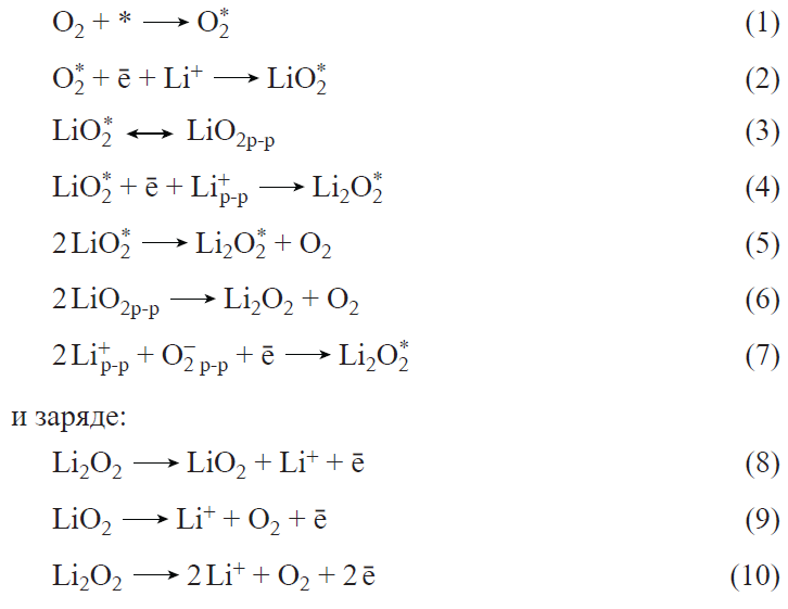
The oxygen reduction reaction (ORR) is accompanied by adsorption of molecular oxygen and subsequent attachment of the first electron and the Li+ ion. The addition of the first electron is considered to be the rate-limiting step for ORR.[154] The resulting lithium superoxide is then converted to peroxide through disproportionation or electrochemical reduction. Proceeding from the weight of Li2O2 as the major solid product of ORR, the theoretical energy density for LAB is 3505 W h kg–1 without considering the weights of other components of the system.[155]
Starting from early studies related to LABs,[156-158] passivation of the electrode surface by the lithium peroxide deposit, which has a very low electrical conductivity, has been considered to be the main cause of voltage loss during the discharge. A number of studies address the effect of Li2O2 nucleation features and deposit morphology on the passivation rate and, hence, on the pattern of the LAB discharge curve.[159-161] When the current density is 0.005 – 0.025 mA cm–2 (see Ref. 159) or 0.1 – 0.2 mA cm–2 (see Ref. 161), the formed Li2O2 particles are mainly large (200 – 400 nm) and shaped like discs or thoroids. At higher current densities (up to 1 mA cm–2), a layer of small (20 – 100 nm) needle-like Li2O2 particles or a Li2O2 film is deposited.[160] Apparently, in the latter case, the passivation of the electrode surface occurs more rapidly, which accounts for the low discharge capacity of LAB (approximately 2 mA h cm–2). Moderate current densities result in the formation of large Li2O2 particles, the active surface area of the electrode decreases more slowly and, hence, a higher capacity is generated (up to 7 mA h cm–2). It is noteworthy that there is no consensus in the literature regarding the influence of lithium peroxide deposits on the mechanism of charge transfer across the electrode/electrolyte interface. According to simplified models, the Li2O2 deposit completely covers the electrode surface during the discharge, and electron transfer occurs via the tunnelling effect.[162] In other models that take into account the experimental data on the actual Li2O2 structure, the deposit is assumed to be permeable for the electrolyte, and charge transfer can occur either through the electrode surface or through the Li2O2 surface.[163]
Korchagin et al.[164-166] proposed a voltammetric procedure for quantitative evaluation of passivation of the positive electrode by solid products during the LAB discharge. As the passivation criterion, the authors used the degree of electrode coverage with the reaction product (lithium peroxide) found from the decrease in the electrical double layer capacitance (CEDL) upon discharge. It was shown that CEDL can be considered as a criterion for prediction of the discharge characteristics of LAB upon variation of the active material and electrolyte compositions.
Lithium peroxide formed upon the discharge of LABs decomposes directly to oxygen and lithium ion during charging (without the formation of LiO2).[167] Thus, the oxygen reduction and oxygen evolution reactions in a lithium-containing non-aqueous electrolyte proceed via different pathways. These differences complicate the search for the most effective electrolytes and active materials.
As a rule, both charge and discharge characteristics of LABs are limited by processes at the positive (air) electrode.[168-170] According to the typical potential distribution in a Li – O2 system, the overpotential at the lithium electrode during discharge is at a level of ~ 0.02 V, with the main voltage loss in LAB being attributed to the ORR overpotential.[171] In turn, charging of LAB starts with a fairly sharp rise in the voltage, which is due to the high overpotential of Li2O2 oxidation. The overpotential minimization during the discharge and charging is essential not only for achieving high capacity, but also for stable operation of all LAB components. The key ways to implement this condition include the synthesis of positive electrode materials that possess catalytic activity toward reactions occurring during both discharge and charging and the search for additives to the electrolyte that can alter the mechanism of electrode reactions (redox mediators).
Among the requirements to active materials for the positive electrode, mention should be made of high electrical conductivity (at least 0.1 S cm–1), chemical stability, and a large surface area (at least 50 – 100 m2 g–1) accessible for lithium peroxide deposition. Active materials can be conventionally divided into four types:[172-177]
(1) carbon materials (CMs) of various origin, including nanostructured and heteroatom-modified CMs;
(2) noble metals (in particular, Pt and Au) and their alloys;
(3) transition metals and their complexes such as metal phthalocyanines;
(4) sulfides, simple and complex metal oxides.
Table 1[178-195][196-206] presents the best charge – discharge characteristics reported in the literature. The maximum discharge capacity values correspond to a LAB discharge with a voltage drop from OCV (typically ~ 3 V)[155] to 2 V. It can be seen that these values reach 30 000 mA h g–1 (in relation to the weight of the active material), which markedly surpasses, in particular, typical characteristics of lithium-ion batteries (the capacity of the cathode material is 150 – 250 mA h g–1). However, the permissible depth of discharge during LAB cycling is no more than 5 – 10% of the maximum value (for lithium-ion batteries, it ranges from 20% to 80 – 90%), while the number of cycles achieved in most studies does not exceed 200 – 300 (for lithium-ion batteries, the average value is between 500 and 2000). The improvement of these characteristics is a priority task on the way to practical implementation of LABs that would be competitive with lithium-ion batteries.
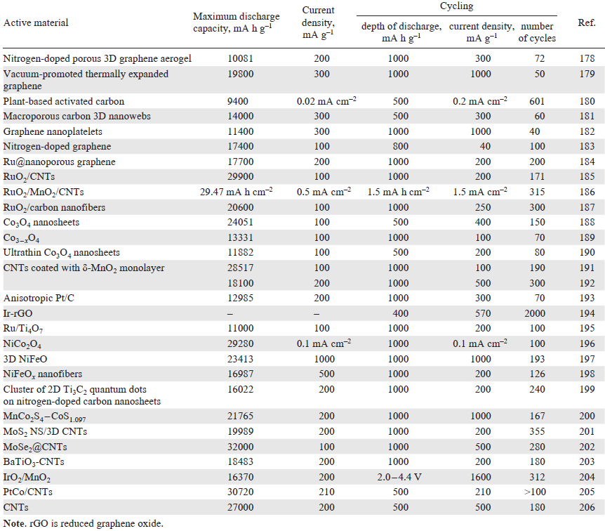
It is worth noting that the most effective systems typically contain carbon materials, in particular graphene, and carbon nanotubes (CNTs) in various forms. Graphene was first studied in a LAB cathode as nanosheets.[207] The discharge capacity achieved in this way was more than four times higher than those of carbon black-based LABs. The synthesis of functionalized graphene nanoscales provided a capacity of up to 15 000 mA h g–1.[208] These high performance characteristics are attributable to the formation of a bimodal pore structure in the active layer, in which small pores serve as active sites for ORR, while larger pores facilitate fast oxygen diffusion to small pores (Fig. 12).
![[{"id":"9RYDHXQnL4","type":"paragraph","data":{"text":"Schematic view of functioning of the active layer of the positive electrode with a bimodal pore structure during LAB discharge"}}]](/storage/images/resized/dDBZnxzS165QXd1X8qci6rl14l7Hk5JZe22AtJXq_xl.webp)
Liu et al.[209] demonstrated the possibility of successful application of graphene oxide. The authors reported the synthesis of porous three-dimensional boron-doped reduced graphene oxide (rGO), which provided a capacity of up to 18000 mA h g–1.[210] These high performance characteristics are achieved owing to facilitated transport of lithium ions and oxygen through the three-dimensional porous catalyst matrix with a high content of defects and functional groups.
Quite a few studies are devoted to the use of carbon nanotubes (CNTs) as active materials for LABs.[172][206][211][212] Carbon nanotubes have high electrical conductivity, thermal and chemical stability, and extensive surface with a branched pore structure. These properties are in full demand for the operation of the LAB positive electrode. The use of functionalized CNTs with a specific pore volume of up to 3.6 cm3 g−1, an average pore size of 40 nm, and a specific external surface area of 270 m2 g–1 provided a discharge capacity of 27 000 mA h g−1,[206] which is one of the best results to date.
Currently, only a small number of publications address the LABs containing platinum group metals (see Table 1). These catalysts were extensively studied in the early stages of LAB development, which was due to attempts to identify a correlation between features of ORR in aqueous solutions, in which platinum has the highest activity, and the features of ORR in non-aqueous electrolytes.[213] However, currently the number of studies devoted to the use of platinum group metals in LABs has decreased. This is due not only to the high cost of these catalysts, but also to their high activity toward undesirable decomposition of the electrolyte and materials that form the positive electrode. Furthermore, unlike aqueous media, in aprotic electrolytes, noble metals do not show significant advantages over CMs.[214][215]
The LAB performance is largely determined by the compatibility of the chosen active material and the electrolyte. As for other lithium-based energy storage devices, the two main types of electrolytes for LABs are liquid and solid aprotic electrolytes. In addition, LAB electrolytes must meet additional requirements: high oxygen transport properties and high oxygen solubility (oxygen diffusion coefficient above 10–5 cm2 s–1 and solubility above 2 mmol L–1), low vapour pressure (better below 10 Pa at 20°С to minimize evaporation), and stability in the presence of intermediates of the oxygen reduction and evolution reactions.
The lithium salts used for the synthesis of electrolytes for LABs include LiPF6, LiBF4, lithium bis(trifluoromethanesulfonyl)imide (LiTFSI), LiClO4, LiSO3CF3, and LiNO3.[216] In early studies dealing with LABs, organic alkyl and alkylene carbonates, particularly ethylene carbonate and dimethyl carbonate, were used as solvents. However, subsequently, electrolytes based on these solvents were shown to be unstable, because of electrolyte interaction with superoxide ions.[217] It was found that CO2 is released during charging.
Ethers, in particular diethylene glycol dimethyl ether (diglyme), tetraethylene glycol dimethyl ether (tetraglyme), and dimethoxyethane are much more stable than alkyl and alkylene carbonates, although during LAB cycling with a discharge depth of approximately 100%, signs of ether degradation appear as early as in the second cycle.[216] Comparative analysis of the studies dealing with the use of ethers and glymes as solvents for LABs demonstrated the advantages of tetraglyme for LAB cycling caused by high solubility of lithium salts, low vapour pressure, and a broad electrochemical window.[218]
Sulfoxides (in particular, DMSO) as solvents have relatively low volatility and high transport properties for oxygen and lithium ions and are widely used for LABs.[214] Meanwhile, in some studies, DMSO was found to decompose during LAB functioning to give a number of products such as LiOH, dimethyl sulfone, and Li2SO3.[219][220] In addition, DMSO also reacts with lithium, which requires the use of a protective layer stable in DMSO on the negative electrode.
The conversion reactions of the intermediates in the electrolyte during LAB operation are mainly determined by the electrolyte composition rather than by the nature of the active material of the positive electrode. A catalyst deposited on the electrode can capture superoxide ions, which increases the reversibility of the discharge process, but does not fully resolve the issue of passivation the active electrode surface by lithium peroxide. As an alternative approach to facilitate the charge exchange between the electrode and Li2O2, it was proposed to use redox-active molecules (redox mediators).[221-223] The mechanism of action of redox mediators may be based on the oxidation of the mediator anion during LAB charging, followed by diffusion toward Li2O2 particles and chemical reduction (Fig. 13a). For effective functioning of a redox mediator, its potential must be 0.3 – 0.4 V higher than the open-circuit potential of the positive electrode.[224]
![[{"id":"AH4zO1Wvb_","type":"paragraph","data":{"text":"(<i>a</i>) Schematic picture of the redox mediator mechanism of Li<sub>2</sub>O<sub>2</sub> oxidation. X– is the redox mediator anion. Copyright Russian Chemical Reviews (A.Yu.Tsivadze et al. Russ. Chem. Rev., 95 (5), RCR5200 (2026)). (<i>b</i>) Charge – discharge curves of LAB based on CNTs with 0.05 M LiI + 1 M LiClO<sub>4</sub>/DMSO electrolyte and 20 PtCo/CNTs with the 1 M LiClO<sub>4</sub>/DMSO electrolyte.<sup>222</sup> (<i>c</i>) Charge – discharge curves of LABs with and without iron phthalocyanine (FePc) mediator.<sup>223</sup> Copyright American Chemical Society. (<i>d</i>) Charge – discharge curves of LAB based on rGO and the 0.05 M LiI + 0.25 M LiTFSI/dimethyl ether electrolyte.<sup>209</sup> Copyright The American Association for the Advancement of Science."}}]](/storage/images/resized/n8W4fxGRW4cniunRm56ZtzZDmWic9aqDb7nv1W3J_xl.webp)
It was shown that on going from 20 PtCo/CNTs without a mediator to CNTs with a 0.05 M LiI mediator, the cycling characteristics of LAB increase virtually twofold (Fig. 13b).[222] A decrease in the charging voltage during LAB cycling was also observed upon the addition of redox mediators such as tetrathiafulvalene and ferrocene,[221] iron phthalocyanine (Fig. 13c),[223] and quinones.[225] Using the stable I3–/I– redox couple and an rGO-based active material, stable cycling for 2000 cycles was attained with an energy efficiency of 93.2% (Fig. 13d ).[209] However, the practical value of these results is reduced by the use of low current density (0.02 mA cm–2) and low loading of carbon material on the electrode (~ 0.02 mg cm–2). In addition, Li2O2 is formed only when iodide concentration is 0.01 M or lower, while increase in the I– concentration leads to the formation of LiOH, which cannot be reversibly oxidized.[226]
In addition to the general drawbacks of lithium energy storage devices with liquid electrolytes, LAB presents an additional problem of solvent evaporation, since LAB is exposed to an oxidative medium on the positive electrode side. A possible solution to this problem is the use of solid electrolytes, which forms so-called all-solid-state LABs. In the general case, the solid electrolyte is a polymeric, ceramic, or composite lithium-conducting membrane, which prevents entry of impurities from the air (O2, CO2, and H2O) to the lithium electrode. The mechanism of current-producing reactions in all-solid-state LABs does not differ from that in liquid-type LABs.
The use of polymer electrolyte (based on polyacrylonitrile) in LABs was reported for the first time in 1996.[227] However, the discharge capacity of this LAB was 1410 mA h g−1, which is markedly lower than the values achieved to date (seeTable 1). In the subsequent 10 – 15 years, the attention of researchers was mainly concentrated on liquid-electrolyte LABs. In 2011, Hassoun et al.[228] described LAB with a zirconium oxide-doped polyethylene oxide (PEO)-based composite electrolyte; however, the value of this study is limited to the data on electrochemical transformations of oxygen in a non-aqueous environment, as the discharge capacity of the LAB was less than 400 mA h g–1. Balaish et al.[229] tested a polymer electrolyte based on lithium triflate and PEO for LAB operating at a temperature of approximately 80°С, which is necessary to generate a reasonable ionic conductivity upon spherulite melting. A polymer electrolyte based on polyvinyl alcohol was also tested.[230] However, these works were not pursued further due to the low performance characteristics achieved for this LAB (discharge capacity from 250 to 2500 mA h g–1).
NASICON type ceramic electrolytes Li1 + xTi2 – xAlx(PO4)3 with high lithium ion conductivity and chemical stability in the presence of water are of particular interest. However, these electrolytes are unstable in contact with lithium metal, which requires the formation of a Li/solid electrolyte interface. Optimization of the LAB architecture with a NASICON type electrolyte and an oxygen-selective membrane resulted in up to 100 cycles achieved in LAB testing in air.[231] However, further research is needed to reduce the interfacial resistance in all-solid-state LABs and to increase the ionic conductivity of the solid electrolyte.
The prospects for the use of Nafion type sulfonated cation exchange membranes as electrolytes for LABs have been studied.[206][232][233] Before being used in LABs, the Nafion membrane is converted to the lithium form (Li-Nafion), thoroughly dried, and impregnated with a suitable non-aqueous solvent (plasticizer) to generate a network of channels providing ion transport within the electrolyte structure. The highest degree of swelling and, consequently, high conductivity of Nafion membranes are achieved in aprotic solvents such as DMSO and DMF.[234] Li-Nafion has a good stability in contact with lithium peroxide.[235] The use of a thin Nafion 212 membrane in combination with a positive electrode based on CNTs that possessed high volume, surface area, and pore size considerably increased the discharge capacity of LABs compared to that of liquid electrolyte LABs (from 20 000 to 27 000 mA h g–1 for a current density of 300 mA g–1).[206] The improvement of LAB performance characteristics on switching from liquid electrolytes to Li-Nafion can be attributed to the prevention of flooding of the positive electrode; as a result, the effective oxygen diffusion coefficient increases and independent channels that transport oxygen and lithium ions to the reaction zone are formed. Considering the lithium electrode, the possible benefits of Li-Nafion include suppression of dendrite formation and decrease in the rate of oxygen crossover to lithium. It was also shown that Li-Nafion LAB can operate in a dry air atmosphere.[233] However, the prospects of this system for operation in a real air environment remain a subject for further research.
One of the challenges faced by practical implementation of LABs is to ensure safe use of lithium and also to prevent lithium corrosion in contact with the electrolyte and with water and CO2 impurities that enter the system from the external environment along with air. Correspondingly, a priority task in the design of an effective negative electrode for LABs is to protect lithium metal. This part of the review addresses approaches to the protection of lithium electrode that have been studied directly during LAB operation. Among these approaches, note the fabrication of protective layers on the lithium surface, the replacement of lithium metal with another lithium-containing material, modification of the electrolyte composition in order to enhance lithium stability, and positioning of water-repellent or oxygen-selective membranes (OSM) at the positive electrode/external environment interface.
For the formation of stable SEI, a lithium – air battery based on lithium anode and CNT-containing cathode was initially discharged in an argon atmosphere.[236] As this took place, by-products formed on the surface of both electrodes because of partial decomposition of the salt and the solvent. This activation provided an increase in the cycle life in comparison with LABs tested without the activation stage. Another approach used for lithium protection implies the formation of a carbonate- and carbon-based layer on the surface during pretreatment (ten successive charge–discharge cycles) in a CO2 atmosphere.[237][238] It was shown that this SEI increased the cycle life of LABs from 11 to 700 cycles in an air-mimicking atmosphere. According to density functional theory calculations, a fairly stable interface is formed between Li and Li2CO3, preventing nitrogen and oxygen from getting to the lithium surface. It is noteworthy that stability of artificially formed SEI on long-term testing or even holding at OCV remains an unsolved issue. In addition, this SEI can further increase the cell resistance.
Attempts to replace lithium metal by other lithium-containing materials, in particular lithiated CMs or LixMy alloys, have been made with the goal to increase the stability of LAB negative electrode.[239][240] It was shown that the formation of a Li-CNT composite anode consisting of lithium pretreated with octadecylphosphonic acid for the fabrication of stable SEI and embedded into a carbon matrix prevents changes in the lithium volume during cycling and the dendrite formation. A drawback of LABs with this type of anode is their low discharge capacity, which is comparable to that of lithium-ion batteries but falls far short of the theoretical parameters of LABs. A good cycle life (667 cycles) was achieved by using the LiAlx alloy containing 0.2 mass % Al.[241] The high performance characteristics were attributed to the formation of a stable thin SEI based on lithium compounds and Al2O3 .
It was noted[242][243] that replacement of liquid electrolyte by a gel is beneficial as regards the stability of the lithium electrode and LAB performance as a whole. Zhao et al.[243] described the use of a nanowire-reinforced hybrid gel polymer electrolyte (GPE) as both a separator and an electrolyte for LAB.[243] The GPE synthesis was performed using MnOOH@Al2O3, tetraglyme, poly(vinylidene fluoride-hexafluoropropylene) (PVDF-HFP), LiClO4, and LiNO3 . Owing to the enhanced mechanical strength, high ionic conductivity, and suppression of dendrite formation in GPE, the resulting LABs exhibited long cycle life (500 cycles).[244][245]
As regards LAB architecture, a simple method for preventing entry of undesired impurities into the system from air is the use of oxygen-selective membranes. The following groups of materials are of interest for OSM development:[246]
(1) fluorinated hydrocarbons, polyethers, polyperfluoroalkyl oxides, and amines;
(2) polysiloxanes, including fluorinated ones, silicone oils, and methacrylates.
Other materials tested as OSMs for LABs include the commercial Melinex 301H material based on polyethylene terephthalate; polyethylene of various density, zeolites, or Teflon supported on porous nickel, Teflon matrix filled with silicone oil, etc.[208][247][248]
Unfortunately, all materials tested as OSMs have insufficiently high oxygen permeability, which limits the discharge capacity that can be achieved for LABs. In terms of cost – performance ratio, low-density polyethylene is a promising option for OSMs. Characteristics of a 15 μm film correspond to an average density of ~ 0.9 g cm–3, water permeability of ~0.03 × 10⁻¹¹ g m–1 s–1 Pa–1, and oxygen permeability of ~ 4 × 10–11 mL m–1 s–1 Pa–1.[249] In the future, it would be of interest to conduct LAB tests using films of this type.
As materials for LABs are being developed, works on the design of LAB prototypes suitable for practical application become more and more relevant. The optimal design should provide the maximum energy density, good electrical contact between the electrodes and current collectors with minimal risk of short-circuit, protection of lithium metal from water, and the maximum surface area of the positive electrode accessible for oxygen or air.
In most studies, LABs are tested using prototypes that closely resemble the cells of lithium-ion batteries used in laboratory research: Swagelok cells (Fig. 14a) and coin cells. However, these cells are not optimal for the design of LABs due to their rigid structure composed of metallic components and limitations on electrode size. Some studies address pouch prototypes.[168] The housing and current collectors in such devices are usually made of thin foil; this minimizes the weight of the housing, but brings about the problem of high resistance between the electrodes and current collectors due to insufficient compression of the components.
![[{"id":"tjwcfkgOmU","type":"paragraph","data":{"text":"(<i>a</i>) Swagelok cell for LAB testing. Copyright Russian Chemical Reviews (A.Yu.Tsivadze et al. Russ. Chem. Rev., 95 (5), RCR5200 (2026)). (<i>b</i>) Design of flexible and wearable LAB.250 Copyright Wiley-VCH. (<i>c</i>) Discharge capacity and corresponding design of various LABs: Swagelok cells (electrode area of 1.13 cm<sup>2</sup>); LAB cell operating in the free convection mode (electrode area of 25 cm<sup>2</sup>); LAB cell operating in the forced convection mode (electrode area of 25 cm<sup>2</sup>).<sup>205</sup> Copyright Elsevier. (<i>d</i>) Experimental setup for flow type non-aqueous LAB with an electrolyte pump.<sup>251</sup> Copyright Wiley-VCH. (<i>e</i>) Structure of coaxial LAB and functioning diagram during charge and discharge.<sup>252</sup> Copyright Wiley-VCH."}}]](/storage/images/resized/AuUQccvGTlDbL1it7k74AYT5wGwus7KT0aYvCOKP_xl.webp)
As an alternative to pouch and coin prototypes, a flexible and wearable LAB functioning without a housing was proposed.[250] In this design, the positive and negative electrodes were criss-cross-woven and, hence, tightly pressed to each other; in addition, the protective polymer film formed on the lithium surface prevented lithium corrosion in the presence of water and also served as both an electrolyte and a separator. This LAB design (Fig. 14b) provided an energy density of more than 500 W h kg–1 (with a maximum depth of discharge) and cycle life of more than 100 cycles (for approximately 10% depth of discharge).
Since the main voltage loss in LABs is caused by processes at the positive electrode, optimization of the electrode architecture is a key issue in the LAB design.[251-253] The most significant parameter characterizing the positive electrode performance is the capacity per geometric surface area (mA h cm–2), which is directly related to the prototype size. Lin et al.[253] proposed an architecture for the graphene-based positive electrode for LAB with a high loading of active material (graphene) (10 mg cm–2),[253] which is approximately an order of magnitude greater than the loadings used in most studies. The electrode was formed by dry pressing of holey graphene e without the use of a solvent or a binder. The resulting electrode was characterized by a high content of pores accessible for oxygen and electrolyte, which provided a discharge capacity of up to 40 mA h cm–2.
A gel consisting of CNTs, LiTFSI, tetraglyme, and polyurethane was fabricated.[254]The gel was cut into granules with an average size of 50 – 200 μm, which were then pressed to achieve the optimal ionic/electronic conductivity and porosity. In the resulting positive electrode, the spaces between the granules served as channels for oxygen diffusion; the absence of liquid electrolyte eliminated the problem of flooding and capillary effects. The highest discharge capacity of LABs with this electrode was up to 55 mA h cm–2, and 170 cycles were obtained in the partial discharge mode. It is noteworthy that despite the advantages of GPE-containing LABs over liquid electrolyte LABs, the solid electrolyte system is less adapted to the periodic change in the volumes of the positive and negative electrodes during cycling. This issue requires further investigation, as changes in the electrode volume could make electrodes peel off from the electrolyte or cause a short circuit.
The described LABs were tested under conditions of natural convection of the oxidant; for increasing the power characteristics, it is possible to arrange forced oxygen or air supply to the positive electrode; this was done for scaling-up the area of LAB electrodes from 1.13 to 25 cm2 (Fig. 14c) using some principles of operation of a hydrogen – air fuel cell:[205]
— electrodes are separated by a thin, non-compressible separator or membrane;
— active material is deposited on the microporous side of the gas diffusion layer (GDL) facing the membrane;
— oxygen is supplied to the macroporous side of GDL in the forced convection mode through a plate with gas distribution channels.
The total capacity of the scaled-up prototype was 0.375 Ah, with the cycle life being more than 100 cycles. Using similar principles, a LAB battery consisting of three single cells was fabricated, providing a capacity of 1.07 Ah and a cycle life of up to 50 cycles in a dry air atmosphere.[255]
Since the discharge capacity of LABs is limited, first of all, by the ability of the positive electrode to reversibly accumulate Li2O2, a periodic or continuous renewal of the electrode surface should obviously increase the energy density. This was implemented in a flow system that implied pumping of the electrolyte through the cell (Fig. 14d ).[251][256] The manufactured prototype provided an energy density of 800 W h kg–1; however, the complexity of the system design, the need to use pure oxygen and an electrolyte pump cast doubt on the prospects for the practical application of such LABs.
Pan et al.[252] proposed coaxial LAB (Fig. 14e) with a positive electrode based on oriented CNTs possessing high electrical and thermal conductivity.[252] As the electrolyte, the authors used a polymer obtained by mixing the ionic liquid 1-n-butyl-1-methylpyrrolidinium bis(trifluoromethanesulfonyl)imide, LiTFSI, and PVDF-HFP as the electrolyte. For cells of this configuration, the authors implemented a heated LAB with an operating temperature of up to 140°C, which exceeds that of most analogues described in the literature, and excellent cycle life (380 cycles) at a high current density (up to 10 A g–1). The considerable deterioration of performance characteristics on passing to testing at room temperature can be named as a drawback.
Thus, analysis of studies addressing LABs all over the world demonstrates, on the one hand, the persistent interest in this issue and, on the other, the fact that now there are no materials and scientific and engineering solutions that would enable the implementation of a LAB prototype ready for practical application. Despite the uniquely high theoretical characteristics of lithium – air electrochemical systems, commercialization of LABs requires a substantial increase in the achieved cycle life, acceptable depth of discharge, and stability in air. Solution of these problems would allow this energy storage system to occupy a niche in the power supply market.
e Graphene sheets with holes in the basal plane.
6. Redox flow batteries: stationary energy storage devices
Energy storage systems differ in their role in power supply stabilization. Large energy storage systems, with a capacity of hundreds of MW h, are used to stabilize power grids. As a rule, they are located near wind or solar power facilities at the power grid nodes. This location is commonly referred to as ‘before the meter’, that is, location upstream of the consumer energy meters. The energy storage systems located at the consumers site, ‘behind the meter’, are used to reduce the consumer expenses for generation of excess infrastructure required to handle relatively infrequent consumption peaks. These energy storage systems also allow consumers to store cheap electricity during off-peak hours for later use during peak hours. Some energy storage devices are used as backup power sources for consumers. The ‘behind the meter’ storage devices are classified into industrial and residential ones. Correspondingly, consumer energy storage devices vary in energy storage capacity and purpose.
Fig. 15 shows the data of 2021 and forecasts for 2030 on the total global power of energy storage devices (MW) segmented according to the positions of grid-connected storage devices.
![[{"id":"f8kAxEQqTo","type":"paragraph","data":{"text":"Data of 2021 and forecasts for 2030 on the total global power of energy storage devices (MW) segmented according to the positions of grid-connected storage devices (https://www.pv-magazine.com/magazine-archive/strong-growth-ahead-for-storage/(accessed on April 1, 2026)."}}]](/storage/images/resized/TvYT3DP9Kms2BkAEN63RiXogwYXBHn6X0Ab7embc_xl.webp)
An important characteristic of an energy storage device is the energy storage capacity for operation at the rated power. Energy storage devices are typically designed to be fully discharged over a period of 2, 4, 6, or more hours. The greater part of stationary energy storage systems are designed for two complete charge–discharge cycles over 24 h. Depending on the role of energy storage devices, different requirements are imposed on them.
Comparison of various energy storage systems is based on the levelized cost of storage (LCOS).[257] This value is calculated over the entire service life of an energy storage system. The numerator comprises the capital costs of manufacture of the energy storage system, operating costs, maintenance costs, costs of replacement of parts, costs of installation of additional sections to compensate for the decline in the energy storage capacity, as well as disposal costs at the end of the life cycle of the device. The denominator represents the amount of energy obtained from the energy storage system over its entire operational life.
6.1. Principles of action of redox flow batteries
Redox flow batteries (RFBs) are rechargeable electrochemical power sources functioning on the same principles as other electrochemical power sources. The major difference is that in RFBs, reactants for current-producing reactions at the electrodes and the products of these reactions are dissolved in liquid electrolytes located in separate tanks. In this respect, they are similar to fuel cells. RFBs consist of three main blocks: electrochemical reactor in which current-producing reactions take place, separate tanks containing dissolved reactants and reaction products, and pipelines with pumps that feed chemicals into the electrochemical reactor (Fig. 16a).[258]
![[{"id":"4xCX8-0lCJ","type":"paragraph","data":{"text":"(<i>a</i>) Diagram of a single cell of a flow battery. (<i>b</i>) Connection of single RFB cells into a stack.<sup>258</sup> Published under the Creative Commons License."}}]](/storage/images/resized/qaI2YMMLA6Jj8AP3JIAM6nsTdwhqd8KcAWRyKaBo_xl.webp)
The energy storage system also includes monitoring and control devices, grid connection equipment, various fire safety means, and parts for preventing and mitigating the consequences of emergency situations. This design accounts for the main advantages of RFBs over other electrochemical power sources. If it is necessary to increase the capacity of the energy storage device, additional reagent tanks are installed. In this case, the expensive parts of the energy storage system, the reactor and the auxiliary equipment, remain virtually unchanged. In addition, in the case of electrolyte degradation, the composition of electrolytes can be corrected, or electrolytes can be partially or completely replaced. The size of reagent tanks can be much greater than the size of electrochemical reactor and storage system monitoring and control devices. Correspondingly, the energy storage capacity is determined by the energy storage capacity of the reagent solutions located in the tanks. Most often, reagent solutions of moderate concentrations of up to 2 mol L–1 are used in RFBs. Consequently, RFBs are markedly inferior in the energy storage capacity to other types of electrochemical power sources, in which the electroactive materials are typically present in their pure solid state.
The electrolyte that is circulated in the positive electrode circuit is often called, for brevity, the posolyte, while the electrolyte circulated in the negative electrode circuit is, correspondingly, called negolyte. The positive and negative electrode compartments in the electrochemical reactor are separated by a diaphragm or a selective ion-conducting membrane, which prevents mixing of the reagents and migration of electroactive posolyte/negolyte components to the negative/positive electrode. During RFB operation, an ion flux passes through the membranes separating the electrode compartments; in electrical units, the ion flux is equal to the electron current flowing in the RFB external circuit.
None of existing membranes is completely selective. The transport of ions and molecules across the membranes driven by concentration gradients, pressure drop, electroosmosis, and electric potential gradients is called crossover. Crossover can lead to irreversible changes in the composition of negolyte and posolyte during the charge–discharge cycles. When unfavourable changes are accumulated, the electrolyte composition should be corrected. Electroactive materials for RFBs are selected as to be stable in both reduced and oxidized states. The batteries are designed in such a way that there is virtually no discharge at zero load. In the absence of a load, reagent fluxes through the electrochemical reactor are stopped, or even the reagents are completely pumped into dedicated tanks. In the absence of contact with the environment, reagents can be stored in the tanks for almost any period of time.
The electrodes of some RFBs, for example, vanadium flow battery, do not chemically change during the charge–discharge processes. Most often, RFB systems use inexpensive electrode materials, such as carbon felt. If the electrocatalytic activity of the felt is insufficient, it can be enhanced, for example, by generating surface groups or by deposition of particles of electrocatalysts such as metals. In some cases, the service life of RFBs can reach 25 years, with tens of thousand charge–discharge cycles being accomplished throughout the whole time of operation. During this period, neither the power nor the energy storage capacity considerably decreases.
Single RFB cells are connected in series into stacks, similarly to fuel cells. Since the voltage of one cell is usually within 2 V, the voltage across the stack reaches tens of volts. When the cells are electrically connected in series, the electrolytes in the cells are connected in parallel (Fig. 16b). As a result, shunt current of battery discharge flows through the electrolyte located in the pipes that feed the cells of one stack. This current can be reduced by increasing the electrolyte resistance in the pipes, which is achieved by decreasing the pipe diameter and restricting the number of cells connected in series. Usually, the number of cells in a stack is not more than 24. A decrease in the pipe diameter leads to increasing loss of energy for electrolyte pumping[258-260] and somewhat increases the cost of the battery. Due to the presence of shunt currents, the battery operation at low currents, whether charge or discharge currents, is not advisable. Since large energy storage systems usually consist of a number of identical RFB modules, cost-effective operation of the entire system is achieved simply by deactivating some of the modules, so that the remaining modules operate under nearly rated conditions.
As a rule, the capital costs of RFB manufacture exceed those for energy storage systems based on conventional batteries, such as lithium-ion batteries. The benefits of using RFBs include markedly (two times or more) longer service life of the energy storage system, lower operational costs, the absence of necessity of installing new battery sections because of the gradual loss of capacity. Since the RFB electrolytes are usually aqueous solutions, RFBs are virtually fireproof; RFBs with aqueous electrolytes are also free from the thermal runaway problem. This appreciably reduces the costs of fire prevention and firefighting equipment.
Since a portion of the proceeds from the sale of expensive metal salts (such as vanadium salts) contained in the electrolytes is recovered, the end-of-life disposal of RFBs is sometimes much cheaper than that of other electrochemical energy storage devices.
Fig. 17 shows the general view of an energy storage system based on vanadium RFB (5 MW/10 MW h) constructed in 2012 by Rongke Power (China). After more than a decade, the storage system has retained 100% of the storage capacity.f It can be seen from the Figure that the required power/capacity for the storage system is provided owing to installation of a large number of identical RFB modules.
![[{"id":"T_KcC2t1fI","type":"paragraph","data":{"text":"General view of the energy storage system based on vanadium flow battery (5 MW/10 MW h) in Shenyang, China. (Rongke Power; https://rkpstorage.com/projects / accessed on April 1, 2026)."}}]](/storage/images/resized/0Wz520htGuEGvFHLUHwGn51wTuJLGy2qKzydLXvO_xl.webp)
A tabular comparison of the key characteristics of various types of stationary energy storage systems ranging from mechnical and hydro storage systems to RFBs and thermochemical storage systems can be found in a review by Fang et al.[261]
In view of the growing interest in RFB, a number of reviews addressing various aspects of RFB development and application have been published in recent years.[261-275] The publications explore the RFB development starting from the first works dating back to the end of the 19th century.[262][276] At the end of the 19th century, horse-drawn carriages were replaced by vehicles powered by steam engines or electric motors. New electrochemical energy storage devices were actively developed for electric vehicles. The design of some of these storage systems was similar to that of modern RFBs. After 1910, due to the advent of internal combustion engines (ICEs) and switching of the automotive industry from electric motors to ICEs, the interest in RFBs sharply declined and remained low until the oil crisis of the 1970s – 1980s. In the crisis years, almost all trends of RFB development have been advanced. In particular, at that time, vanadium flow batteries were proposed, and later they were commercialized;[277][278] and zinc – bromine RFBs started to be actively developed in those years for the use in stationary energy storage systems and as power sources for electric vehicles.g
There are several main classifications of RFBs. First of all, there are classical RFBs in Which both redox couples are located in liquid electrolytes (Fig. 16a) and hybrid RFBs. In the latter case, the gas/liquid transition takes place in one of the redox couples, e.g., hydrogen/water transition or solid/liquid transition such as metal deposition/dissolution. Another classification of RFBs is based on the nature of the solvent used for electrolytes, that is, RFBs with aqueous and non-aqueous electrolytes. Correspondingly, RFBs with aqueous electrolytes are fireproof, while the latter type can be fire-hazardous. Yet another RFB classification considers the nature of redox couples: RFBs with inorganic and organic electroactive compounds. Organic redox couples in one electrolyte circuit are often combined with inorganic couples in another circuit.
Typically, the cost of redox couple components accounts for a substantial portion of the capital costs associated with RFBs. Flow batteries using organic redox couples are potentially less expensive than analogues with inorganic components. However, only few organic redox couples can withstand tens of thousands of redox cycles,[271] and the synthesis of complex organic compounds may be expensive.
To date, dozens of inorganic and hundreds of organic redox systems have been proposed as electroactive materials for RFBs.[265][266][270][274][275][279][280] While choosing redox couples, it is necessary to consider, first of all, the possibility of solvent decomposition at the operating potentials of RFB electrodes and also ion transfer induced by electrical current across the diaphragm or membrane separating the electrode compartments in the reactor, in particular, crossover of electroactive compounds. The crossover should not induce irreversible changes in the composition of electrolytes within the circuits; in particular, it is necessary to minimize the transfer of redox-couple components,[281] which leads to charge loss.
f Rongke Power; https://rkpstorage.com/projects/ (accessed on April 1, 2026).
g R.Bellows, H.Einstein, P.Grimes, E.Kantner, P.Malachesky, K.Newby, H.Tsien. Development of a Circulating Zinc — Bromine Battery Phase I — Final Report. (1983); https://osti.gov/servlets/purl/5539084 (accessed on April 1, 2026).
6.2. The main types of RFBs
6.2.1. Vanadium RFB
Currently, vanadium RFB predominates among all types of RFBs. Vanadium RFBs are being manufactured by well-known companies such as Rongke Power (China), Sumitomo Electric (Japan), Invinity Energy Systems (UK – USA), CellCube (Austria), and VRB Energy (Canada). Rongke Power developed vanadium RFBs with a total energy storage capacity of 3 GW h.h Vanadium is a relatively expensive metal; most of vanadium mineral reserves are concentrated in Russia and China.
The following single-electron reactions occur at the electrodes of a vanadium RFB in aqueous electrolytes.[277][278][282-284] The single-electron redox reaction of the V3+/V2+ couple occurs at the negative electrode:

A similar reaction of the V5+/V4+ couple takes place at the positive electrode:

The overall reaction can be written as
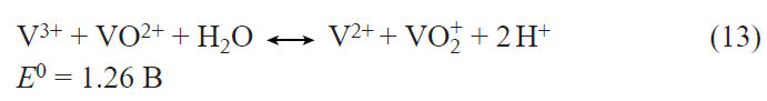
Here and below, the standard redox potentials of redox couples are referred to the standard hydrogen electrode. In both circuits, vanadium ions, which are present in 1.5 – 2 M concentration in each circuit, are dissolved in 4 – 5 M H2SO4 . Vanadium is present in electrolytes as the following hydrated species: [VO(H2O)5]2+; [VO2(H2O)4]+; [V(H2O)6]2+; [V(H2O)6]3+. The reactor compartments are separated by cation-conducting polymer membranes based on perfluorinated sulfonic acids such as Nafion. The mobility and concentration of protons in RFB electrolytes substantially exceed those of vanadium ions; as a result, protons and water are mainly transported across the membrane during battery cycling. Since vanadium ions are present in both electrolyte circuits, the transport of vanadium ions across the membrane, that is, vanadium ion crossover, results in only a slight decrease in the coulombic efficiency of the battery. The imbalance in the compositions of the negolyte and posolyte that develops over time can be corrected by partial or complete mixing of the electrolytes of the two circuits. The hydrogen release that takes place at the negative electrode of the vanadium RFB is the second cause for the imbalance of the negolyte and posolyte compositions. This imbalance can be eliminated by inclusion of an additional electrochemical reactor into the posolyte circuit. In this reactor, the released hydrogen is oxidized with simultaneous posolyte reduction. The solubility of vanadium salts and electrolyte stability define the relatively narrow operating temperature range of the reactor and the electrolyte tanks (+10 to +40°С). When the temperature exceeds 40°С, the hydrated [VO2(H2O)4]+ cation in the posolyte decomposes to give poorly soluble V2O5 , while at temperatures below 10°С, the solubility limit of the V4+, V3+, and V2+ salts is reached. The cell voltage of a fully charged battery is ~ 1.4 V. In charge – discharge cycles, the coulombic efficiency (charge efficiency) of vanadium batteries reaches 95%, while the energy efficiency of the batteries, excluding auxiliary systems, reaches 88%.[282] Carbon felts are used as the RFB electrodes; owing to the high specific surface area, they provide high power outputs for the reactor despite the relatively low electrochemical activity. The electrochemical activity can be increased by additional activation of the felts. The operating current density of vanadium flow batteries is in the range of 0.1 – 0.4 А cm–2.[285] Vanadium contained in electrolytes accounts for up to 43% of the cost of vanadium RFBs.
The relatively low concentration of vanadium ions in electrolytes accounts for the relatively low volumetric energy density of vanadium RFBs, which reaches 35 W h L–1. The levelized cost of storage of approximately 100 MW/1 GW h vanadium RFBs is estimated to be $ 36; 0.21 per kW h.i For comparison, according to the same source, the estimated cost for lithium iron phosphate storage system of the same energy storage parameters is $ 0.17 per kW h.
h Rongke Power; https://rkpstorage.com/projects/ (accessed April 1, 2026).
i PNNL. 2024. Energy Storage Cost and Performance Database; https://www.pnnl.gov/cost-andperformance-estimates (accessed April 1, 2026).
6.2.2. Zinc – bromine RFB
This hybrid system began to develop rapidly during the energy crisis.j The major recent manufacturers are RedFlow (Australia), Primus Power (USA), and EOS (USA). Before 2024, RedFlow produced 3 kW/10 kW h compact modules with a 10-year warranty, which costed about $ 10 000. The dimensions of the compact modules were 83 × 40 × 43 cm. These RFBs were used as energy storage devices and backup power sources for households, small businesses, telecommunications towers, and other facilities in Australia, New Zealand, and Republic of South Africa. Due to the low reliability of the modules and, hence, the high costs associated with warranty repairs, RedFlow ceased operation in 2024. EOS manufactures 150 W/800 W h Eos Z3 modules with dimensions 18.5 × 37.3 × 31.5 cm weighing 20.5 kg; the company guarantees the retention of 88% of the energy storage capacity at the end of the 20-year lifecycle of the battery with a discharge depth of up to 100%. The EOS Cube energy storage system consists of 672 Eos Z3 modules integrated inside a container measuring 2.4 × 4.9 × 2.9 m.
Primus Power manufactures 25 kW/125 kW h EnergyPod 2 modules for electric grids with the claimed lifecycle of 20 years and 70% energy efficiency in the charge – discharge cycles. The geometric current density during the charge – discharge of zinc-bromine RFBs is approximately 20 mA cm–2. The volumetric energy density is 70 W h L–1. The operating temperatures of RFBs are 10 – 50°С.
The main reactions taking place in zinc – bromine RFBs are as follows:[286-289]
Zinc deposition/dissolution takes place at the negative electrode of the reactor:

The bromine/bromide transition occurs at the positive electrode:

The overall reaction is as follows:

The positive electrodes are made of cheap carbon materials, felt, and carbon papers that are specially treated to enhance their catalytic activity. Zinc has long been widely used in chemical power sources. The acidity of electrolytes in the zinc – bromine RFB is maintained at pH 1 – 4.[288][289] Owing to the high overpotential for hydrogen on zinc in this pH range, the corrosion rate of zinc is low, and the current loss for hydrogen evolution during charging is also moderate. At higher acidity levels, the zinc corrosion rate sharply increases. At higher pH, bromine disproportionates to form inactive bromate and bromide, while zinc bromide is hydrolyzed to form poorly soluble basic bromide Zn(OH)Br and zinc hydroxide.
The solubility of bromine Br2 in aqueous electrolytes at room temperature is approximately 0.2 M.[290] Under ambient conditions, bromine is a corrosive and poisonous liquid with a high vapour pressure. The boiling point of bromine at atmospheric pressure is 59°C. When the bromide anion concentration is above 1 М, a considerable part of bromine present in the aqueous electrolyte is incorporated into tribromide and pentabromide anions:[290]
Here Ki is the equilibrium constant of the reaction.
Stronger binding of bromine in the posolyte is achieved using ionic liquids based on quaternary amine bromides, e.g., N-methyl-N-propylpyrrolidinium bromide, which forms stable tribromides in the presence of Br2.[291] In this case, a separate phase of a quaternary amine bromide with bound bromine occurs on the bottom of the posolyte container. Bromine binding in the posolyte maintains a low concentration of dissolved bromine, which decreases the bromine vapour pressure and rules out the formation of the liquid bromine phase. The electrolyte used in RFBs represents an aqueous solution of ZnBr2. The proneness of zinc to form dendrites upon electrodeposition restricts the maximum amount of zinc deposit on the electrode, thus limiting the specific capacity of the zinc electrode to 0.1 – 0.15 Ah cm–2.[289] In an electrochemical reactor, the electrode compartments are typically separated by a porous diaphragm, which somewhat inhibits the growth of zinc dendrites and prevents short-circuit of the electrodes. In addition, the diaphragm acts as a barrier preventing dissolved bromine from entering the negative electrode compartment. The battery manufactured by PrimusPower does not use a diaphragm. The details of this technology have not been disclosed. The levelized cost of storage (LCOS) for the 10 MW/20 MW h zinc – bromine flow battery is estimated as $ 0.226 per kW h.k
The replacement of volatile and toxic bromine in the posolyte by iodine resulted in the development of a zinc – iodine flow battery. Iodine, which is solid under ambient conditions, is dissolved in the aqueous electrolyte as polyiodides, I3–, I5–. The following reaction takes place at the positive electrode of this RFB:

The reaction occurring at the negative electrode is zinc metal deposition/dissolution [reaction (4)].
The overall reaction is

This RFB is currently still in the research phase.[292]
j R.Bellows, H.Einstein, P.Grimes, E.Kantner, P.Malachesky, K.Newby, H.Tsien. Development of a Circulating Zinc – Bromine Battery Phase I — Final Report. (1983); https://osti.gov/servlets/purl/5539084 (accessed on April 1, 2026).
k IESR (2022). Enabling Renewable Energy through Lower Cost and Longer Lifetime Battery Storage. Institute for Essential Services Reform; https://iesr.or.id/en/pustaka/enabling-renewable-energy-through-lower-cost-and-longer-lifetime-battery-storage/ (accessed on April 1, 2026).
6.3. Flow batteries in the early stages of technological development
6.3.1. All-iron RFB
This flow battery uses inexpensive and safe reagents. The battery circuits accommodate acidified aqueous electrolyte containing a supporting electrolyte such as ammonium chloride and iron salts. This is a hybrid flow battery in which the following electrochemical reactions take place.[293] Iron deposition/dissolution occurs at the negative electrode in the presence of chloride ions according to the following reactions:

The reaction that occurs at the positive electrode is as follows:

The overall reaction is

Iron is characterized by low hydrogen overpotential; therefore, to decrease the rates of hydrogen release during charging and corrosion of the iron electrode, pH of the electrolyte should be maintained in the range of 1 – 1.5. The hydrolysis of FeCl3 accompanied by the precipitation of insoluble iron hydroxides and oxides occurs at pH > 3.5. The release of hydrogen at the negative electrode, which takes place in parallel with the deposition of iron metal, shifts the electrolyte pH to greater values. The compartments of the electrochemical reactor of RFB are separated by a cation-conducting membrane. The major species that move across the membrane are ammonium cations and protons. The crossover of iron ions through the membrane results only in a slight decrease in the coulombic efficiency of RFB. The positive electrode is made of carbon-based materials, while the negative electrode is a metal sheet. Iron ions with organic ligands form a large number of water-soluble complexes. The use of complex formation made it possible to shift pH of electrolytes in all-iron RFBs to neutral and even alkaline region.
Twenty five redox couples for all-iron RFBs based on various complex iron ions have been described.[294] Currently, ESS Tech Inc. (USA) is developing 75 kW/380 kW h all-iron flow batteries with 25-year lifecycle providing 20 000 charge –discharge cycles with a warranty period of 1 year. The battery is assembled as a standard 12.2 × 2.4 × 2.9 m container.
6.3.2. Iron – chromium RFB
The iron – chromium system is one of the first redox systems proposed for the use in flow batteries.l This is a classical RFB in Which the components of both redox couples occur in aqueous electrolytes as metal salts. The reaction taking place at the positive electrode is as follows:[295]

At the negative electrode, redox reaction involving the Cr2+/Cr3+ couple proceeds

The overall reaction is

As a rule, porous carbon materials are used for both electrodes, which are subjected to various activation procedures to increase their activity. The compartments of the electrodes are separated by a cation-conducting membrane. Iron and chromium are abundant on the Earth. Redox flow batteries use inexpensive iron and chromium chlorides dissolved in 3 M aqueous HCl. Electrolytes with equal contents of metal (iron and chromium) ions, so-called mixed electrolytes, are used in both circuits. Since the Cr3+ conversion to Cr2+ in the negolyte is never 100%, iron in the negolyte always exists as Fe2+ cations. The same is true for chromium cations in the posolyte, which always exist as Cr3+. Thus, the presence of chromium ions in the posolyte and iron ions in the negolyte has virtually no effect on the processes occurring at the electrodes. The ionic current through cation-conducting membrane is mainly carried by protons. Hence, the crossover of metal cations does not cause irreversible changes in the electrolytes, but slightly reduces the coulombic efficiency of RFBs. Despite the high hydrogen overpotential on carbon materials, the release of hydrogen taking place at the negative electrode changes the balance between the redox forms in the electrolytes of different circuits. This effect can be mitigated by thorough purification of the electrolytes in order to remove impurities that reduce the hydrogen overpotential and by incorporation of an additional balancing cell in which the released hydrogen is oxidized and excess Fe3+ in the posolyte is reduced. At carbon materials, the electrochemical conversions of the Fe3+/Fe2+ couple [reaction (24)] are two orders of magnitude faster that the Cr3+/Cr2+ conversions [reaction (25)]. This necessitates considerable increase in the negative electrode activity without increasing the hydrogen release rate. This can be achieved by introducing metal particles (such as lead or bismuth particles) with high hydrogen overpotential into the negative electrode. Another drawback of this RFB is so-called hydrate isomerism of CrCl3 · 6 H2O, Which implies slow conversion of hydrates 1 and 2 to inactive hydrate 3:
The inactivation of CrCl3 · 6 H2O can be mitigated or even reversed by using appropriate ligands, for example, N-alkylamines. The formation of complexes with iron and chromium cations allows reactions (14) and (15) to proceed at neutral pH. Currently, Redox One (Germany) m is developing an energy storage system based on this RFB.
l L.Thaller. Electrically rechargeable REDOX flow cell[M]. (NASA TM X-71540) (1974); https://nasa.gov/citations/19740013575 (accessed on April 1, 2026).
m https://redoxone.com/technology / (accessed on April 1, 2026).
6.3.3. Zinc – cerium RFB
This hybrid flow battery with an aqueous electrolyte has a very high electromotive force.[296] In the acidic aqueous solution of methanesulfonic acid CH3SO3H, zinc deposition/dissolution takes place at the negative electrode [reaction (14)], while the reaction at the positive electrode is a redox reaction involving dissolved cerium ions:

The overall reaction is

Complete reduction of cerium cations to metal occurs at high negative potentials:

At the potentials of the positive electrode, zinc cations do not participate in any redox reactions. This enables the use of mixed electrolytes containing both cerium and zinc ions in both circuits. Thus, the crossover of cerium and zinc ions does not lead to irreversible changes in the electrolyte during the charge – discharge cycles. Nevertheless, the use of a cation-selective membrane in this RFB is necessary to achieve a high coulombic efficiency. For the full charge, the open-circuit voltage of this RFB reaches 2.5 V. The reactions are carried out in methanesulfonic acid, since only in this acid, the solubility of cerium salts is sufficient to achieve the required energy density of the electrolytes. High voltage and high potential storage capacity of the battery electrolytes keep up the interest in this system despite the number of problems that are still to be solved. Thus, in acidic medium, zinc corrosion and hydrogen evolution reduce the coulombic efficiency of the battery. The dendrite formation during the electrodeposition of zinc also preclude the possibility of achieving a high charge density on the electrodes. Due to the high positive potential of the cerium electrode, it is necessary to use coatings on the positive electrode by noble metals such as platinum and platinum – iridium alloys. Oxygen evolution at the positive electrode also reduces the efficiency of this RFB. In the 2000s, Plurion, a UK start-up, attempted to commercialize this system with no success.
6.3.4. Soluble lead acid flow battery
This is a hybrid battery in which PbO2 and Pb metal are deposited on the electrodes from a liquid electrolyte containing Pb2+ ions. This flow battery does not require a separating membrane and can operate using a single liquid electrolyte tank. The electrolyte used in the battery is lead(II) methanesulfonate Pb(SO3CH3)2.[297] n The solubility of this lead salt in water at room temperature depends on the concentration of methanesulfonic acid (MSA). As the MSA concentration increases to 1 М, the solubility of the salt increases to 2 М. Further increase in the MSA concentration leads to a decrease in the solubility of lead(II) methanesulfonate.
Lead deposition/dissolution takes place at the negative electrode of the cell

The lead dioxide formation/dissolution occurs at the positive electrode:

The overall reaction is

In the testing of a pilot battery comprising a stack of five bipolar electrodes, each with an area of 1000 cm2, more than 100 charge – discharge cycles were successfully completed with an energy efficiency of more than 70%. The lifecycle of the stack was limited due to the formation of lead dendrites on the negative electrode and their growth toward the opposite electrode, the detachment of PbO2 from the positive electrode, the spread of dense PbO2 deposit from the positive electrode over the polymer parts of the stack toward the negative electrode, followed by short-circuiting of the electrodes.
n R.G.A.Wills, C.Poncede Leon, F.C.Walsh. The development of flow batteries from proof of concept to pilot scale (and beyond); https://www.sandia.gov/files/ess/EESAT/2011_papers/Monday/11_Wills_RGAW_EESAT_Abstrct.pdf (accessed on April 1, 2026).
6.3.5. Polysulfide – bromine and polysulfide – iodine RFBs
These are classical flow cells with two electrolyte circuits feeding into an electrochemical reactor, with the electrode compartments separated by a cation-conducting membrane.[298] The posolyte contains an aqueous solution of sodium bromide with dissolved bromine. Depending on the bromine concentration, sodium tribromide and pentabromide are formed in the solution [reactions (17) and (18)]. The negative electrolyte contains an aqueous solution of sodium sulfide and dissolved sulfur; this gives polysulfides Sn2–, n = 2 – 5 (S2–, S22–, S32–, S42–, S52–). The redox reaction involving sulfur incorporated in polysulfides occurs at the negative electrode
At the positive electrode, the redox reaction involving bromine takes place

The overall reaction is
The high solubility of alkali metal sulfides and bromides, as well as polysulfides and polybromides, ensures the potentially high storage capacity of this RFB. The Regenesys start-up attempted to commercialize the polysulfide – bromine redox flow battery, but in 2003, it ceased the operations.
By using iodine instead of bromine in the polysulfide – iodine battery, it is possible to solve the problem of high toxicity of bromine due to the decrease in the battery voltage.
The high flow rates of polybromide/polyiodide and polysulfide species across the cation-conducting membrane result, on the one hand, in pronounced coulombic losses and, on the other hand, in blocking of ion channels in the membrane caused by the formation of elemental sulfur in the channels[299] according to the reaction

The RFB operation is also accompanied by the deposition of sulfur in the pores of the carbon negative electrode of RFB, which results in blocking of a fraction of the electrode surface.
6.3.6. Hydrogen – bromine RFB
This flow battery[300] is largely similar to the hydrogen – chlorine regenerative fuel cells, which have been developed since the 1980s.[301] Due to the presence of a liquid reagent, bromine dissolved in concentrated aqueous HBr, this energy storage device should be classified as a redox flow battery. Hydrogen – bromine RFB suffers from a number of considerable drawbacks. The first one is the hazard and complexity of the storage of gaseous hydrogen. Furthermore, even storage of hydrogen as a gas under elevated pressure of approximately 200 bar provides for not very high volumetric energy density of ~ 400 W h per litre of a cylinder. Bromine is a toxic and corrosive substance. For electrochemical hydrogen oxidation/evolution at the negative electrode of RFB, it is necessary to use expensive platinum catalysts, which are poisoned by bromine arriving from the positive electrode compartment. However, bromine crossover across the cation-conducting membrane does not result in the formation of hazardous mixtures with hydrogen, because, first, bromine and hydrogen do not react at moderate temperatures and, second, in the presence of the platinum catalyst, bromine is reduced to HBr at the hydrogen electrode potential.[302]
This system also has a number of substantial benefits that allow the Dutch start-up Elestor o to hope to achieve LCOS of $ 0.05 per kW h, which is still unachievable for other electrochemical storage devices. The low cost of energy storage in this RFB is due, first of all, to high rates of reactions occurring at both electrodes, low cost of reagents, and maturity of the key technologies involved in this battery.
o https://elestor.com (accessed on April 1, 2026).
6.4. Other RFBs with inorganic redox couples
Titanium is the seventh most abundant metal in the Earth’s crust, accounting for 0.63 mass %. Titanium tetrachloride is a liquid hydrolyzed in acidic medium (pH < 1) to give the TiO2+ cation, which can participate in the reversible electrochemical reaction

As the acidity of the aqueous solution decreases to pH ~ 4, further hydrolysis takes place to give inactive polytitanate complexes.
The potential of reaction (27) is relatively low; hence, this reaction has been proposed for the design of RFBs. The Ti – X systems (X = Fe, Mn, Ce, Br2) were investigated in model flow cells.[303] Aqueous H2SO4, HCl, HNO3, and H3PO4 were used as acidic solutions.
Savinell et al.[304] reported a titanium iron cell with stationary electrolytes using the Fe3+/Fe2+ redox couple (E0 = 0.771 V) at the positive electrode [reaction (24)]. The electromotive force of this cell in the standard state was 0.67 V. A flow cell based on this system was later proposed; it withstood more than 1000 charge – discharge cycles without any loss of efficiency.[305]
Dong et al.[306] reported a redox system comprising the Ti4+/Ti3+ and Mn3+/Mn2+ couples. By the use of the Mn3+/Mn2+ current-forming reaction, the standard voltage of the cell was increased to 1.4 V:

The flow cell made use of mixed electrolytes; in other words, both the posolyte and negolyte contained titanium and manganese cations. The compartments of carbon felt electrodes were separated by an ion exchange membrane. The presence of titanium ions in the posolyte reduced the Mn3+ disproportionation rate

The volumetric energy density of the electrolytes was 23.5 W h L–1.
When cerium salts Ce4+/Сe3+ [E 0 = 1.61 V, reaction (17)] are used in the positive electrode circuit, the standard potential of the titanium–cerium cell is E 0 = 1.5 V.[307] However, all of the above complications associated with the use of the cerium redox couple in the posolyte also fully apply to this system.
The use of the bromine/bromide redox couple with the standard redox potential E 0 = 1.065 V in the posolyte [reaction (15)] provided the design of Ti4+/Ti3+ – Br0/Br– flow battery with a standard potential of 0.97 V.[308] In a ten-cell stack, the electrode compartments were separated by a porous polyolefin diaphragm. The same electrolyte was pumped through the compartments, namely, 1 M Ti(SO4)2 – 1 M HBr – 2 M HCl – 0.5 M CHA, where CHA is 3-chloro-2-hydroxypropyltrimethylammonium chloride, a water-soluble quaternary amine used to bind bromine.
Modestov et al.[309] proposed a lead – iodine hybrid flow battery, with lead dissolution/deposition involving the [PbI3]– complex anion taking place at the negative electrode

and the iodine/polyiodide redox reaction [reaction (19), E 0 = 0.54 V] occurring at the positive electrode. Like iodine, lead iodide is virtually insoluble in water, but in concentrated HI, the solubility of PbI2 at room temperature reaches 1 M.
The systems described above by no means exhaust the variety of inorganic redox couples that can be used to design RFBs. A recent review considers coordination metal complexes, which were used for various RFB designs.[310] The appropriate choice of ligands for a transition metal central ion makes it possible to vary both the solubility and the redox potentials of metal redox couples over wide ranges. The application of coordination metal complexes allows for the use of various types of solvents such as water, organic solvents, and ionic liquids for RFB fabrication.
6.5. RFBs with organic redox couples
The vast diversity of organic compounds offers virtually limitless possibilities for the development of RFBs with non-metallic redox couples. The active materials for this type of flow batteries are subject to standard requirements: high energy density of electrolytes, high solubility of redox couples, lack of toxicity, stability during charge – discharge cycles, fire safety, and low cost. However, particularly these characteristics of organic RFBs may be difficult to implement. The volumetric energy density of electrolytes of organic RFBs rarely exceeds 20 W h L–1. This is usually attributable to the limited solubility of redox couples. Often, an organic redox couple in one electrolyte circuit is combined with an inorganic redox couple in the other circuit. To some extent, this is due to the fact that, despite the wide variety of organic compounds available, it proves difficult to find a suitable organic redox couple for the opposite circuit. All organic RFBs can be divided into two main groups in terms of the used solvent: aqueous electrolyte and non-aqueous electrolyte RFBs.
6.5.1. Organic RFBs with aqueous electrolytes
Redox flow batteries based on aqueous solutions are fire-safe and relatively cheap. The possible water electrolysis imposes restrictions on the choice of redox couples. These restrictions are partly removed by using carbon electrode materials characterized by relatively high oxygen and hydrogen overpotentials. The ionic mobility of organic compounds in aqueous and non-aqueous solutions is usually low; organic redox couples may be non-charged. This necessitates the use of supporting electrolytes in RFBs of this type. The water solubility of redox couples and other requirements to RFB electrolytes considerably restrict the applicable types of organic compounds. Quite a number of organic redox couples used in aqueous electrolyte RFBs were prepared by modification of only few main types of organic compounds. Fig. 18 shows the redox potentials and volumetric capacity of solutions (in electrical units) of the major compounds used in aqueous RFBs.[311] The replacement of hydrogen atoms by polar groups may considerably increase the solubility and redox stability of these key compounds in aqueous electrolytes.
![[{"id":"7U77MAT3aY","type":"paragraph","data":{"text":"Redox potentials and capacities of the main redox couples tested in RFB cells with an aqueous electrolyte. The redox potential values are represented by coloured rhombi: red stands for acidic electrolytes, green corresponds to neutral electrolytes, and blue means alkaline electrolytes.<sup>311</sup> Copyright MDPI (Bazel, Switzerland)."}}]](/storage/images/resized/bZV6PURjsJjoQWvRhQRHAr5BR4HBc2kdFvGzP3vF_xl.webp)
6.5.2. Some redox couples with low redox potentials that are used to produce RFB negolytes
Substituted quinones, naphthoquinones, and anthraquinones are reversibly reduced via a two-electron process of the quinone – hydroquinone type (Scheme 1). The standard potentials of these couples depend on pH of the aqueous medium. Substituted and unsubstituted quinones are unstable during redox cycling in aqueous media and, hence, they cannot be used in RFBs. Naphthoquinone and anthraquinone are virtually insoluble in water. However, quinones containing polar substituents are soluble in aqueous electrolytes. Naphthoquinones, which are markedly more stable than quinones, still rarely withstand more than a hundred charge–discharge cycles in a flow battery. Substituted anthraquinones, in particular anthraquinone-2,7-disulfonic acid, are soluble in aqueous electrolytes up to a concentration of ~ 1.9 M.[312] These compounds have been used in experimental flow cells containing inorganic posolytes.
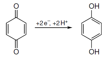
The electrochemical oxidation of pyridine is irreversible and, therefore, it is unsuitable for RFBs with aqueous electrolytes. MeanWhile, bipyridines, salts of methylviologen derivatives, in particular, can be reversibly reduced in two-electron processes and, therefore, they are frequently used in the development of organic RFBs.[313]
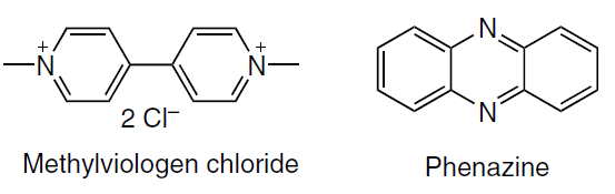
Phenazine-based negolytes with polar substituents were used to design combined RFBs with hexacyanoferrate-based posolytes. The solubility of substituted phenazines in a 1 M KOH solution reached 1.5 M; in combination with the two-electron oxidation of phenazines, this provides a negolyte capacity of 80.9 A h L–1.[314]
6.5.3. Some redox couples with high redox potentials that are used to produce RFB posolytes
Quinones/hydroquinones constitute a large group of organic compounds the redox potentials of which can be varied over a relatively wide range by introduction of substituents. In particular, sulfonic group as a substituent in benzoquinone shifts the redox potential of the quinone/hydroquinone couple to positive values, thus making these redox couples suitable for the use as electroactive compounds in the posolytes.[312]
In non-aqueous media, the stable neutral TEMPO* radical [(2,2,6,6-tetramethylpiperidin-1-yl)oxyl] can be reversibly oxidized to give the TEMPO+ cation.[311][312] The electrochemical and physicochemical properties of the TEMPO*/TEMPO+ couple markedly depend on the introduced substituents. The introduction of a hydroxyl group in position 4 increases the water solubility of the couple from nearly zero (for unsubstituted molecules) to 2 M. This has made TEMPO* derivatives popular oxidants in RFB posolytes.
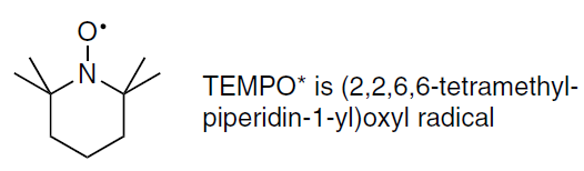
Organometallic compounds, first of all, metallocenes are used more and more often in the posolytes of organic RFBs.[310] Hu et al.[315] showed high stability of RFB cells with pH-neutral aqueous electrolytes containing a water-soluble modified ferrocene in the posolyte and methylviologen in the negolyte. The high solubility of modified ferrocene (up to 4 M), the relatively high open-circuit voltage (1 V), and the high solubility of methylviologen (3.5 M) resulted in a relatively high theoretical energy density for the electrolytes of this RFB: 45.5 W h L–1.
6.6. Organic RFBs with non-aqueous electrolytes
The use of organic solvents substantially expands the range of organic compounds applicable for current-forming reactions.[266] Furthermore, organic solvents also greatly expand the range of potential substituents that can be used to modify the properties of organic redox couples. By introducing substituents in the main organic redox couples, it is possible to finely tune the redox potentials, solubility, and chemical stability of electroactive compounds. The complexity of organic synthesis, on the one hand, and the great variety of substituent groups, on the other hand, makes computer simulation an important tool of research. All types of redox couples listed in the previous Section can also be used in non-aqueous electrolytes. Redox-active groups used as substituents make it possible to prepare organic compounds with a few (e.g., two) separate reversible one- or two-electron redox transitions spaced apart on the potential scale within the stability window of the organic electrolyte. When this organic compound is placed into both electrolyte circuits, symmetrical flow redox battery is formed.[316] In the battery, an electrolyte of identical chemical composition is present on both sides of the separator, but the redox-active compound occurs in different oxidation states. The symmetrical organic redox battery is a direct analogue of the all-iron battery or vanadium battery discussed above. This partly resolves the issue of the crossover of electroactive couples in the redox flow battery using organic solvents. Evidently, the design of cycling-stable molecules with two reversible redox couples separated by more than a volt on the potential scale presents a challenging task. The increase in the size of organic redox couples by introducing large substituents leads to increasing electrolyte viscosity, decreasing diffusion coefficients of electroactive components, and increasing transport losses.
Non-aqueous electrolytes make it possible to move beyond the so-called potential window of aqueous electrolytes restricted by hydrogen and oxygen evolution reactions. The main non-aqueous solvents that were used in RFB-related studies include formamide, propylene carbonate, ethylene carbonate, dimethyl sulfoxide, tetrahydrofuran, and some other. Lithium salts such as lithium bis(trifluoromethanesulfonyl)imide LiTFSi are used as supporting electrolytes in non-aqueous-electrolyte RFBs. The high solubility of redox couples in a pure solvent usually considerably decreases in the presence of a supporting electrolyte. The ion exchange membranes designed for aqueous electrolytes are of low efficiency in non-aqueous electrolytes; in addition, their resistance is an order of magnitude higher in non-aqueous electrolytes than in aqueous solutions. The use of separators with pores of a few nanometres size allows the use of redox-active oligomers and even redox-active polymer particles in the batteries. However, in RFBs using small-molecule redox couples, the separators prove to be ineffective. As a rule, high cycling performance of RFB cells with organic solvents was achieved at low concentrations of organic compounds of approximately 0.1 M. At higher concentrations, there is a higher contribution of side reactions that lead to the loss of active compounds and to film deposition on the electrodes. The regeneration of organic electrolytes is a complex and costly procedure. Almost all of the listed organic electroactive couples are toxic. Non-aqueous solvents are toxic and fire hazardous; therefore, their use in RFBs is expedient only if they provide a decrease in the levelized cost of storage (LCOS) compared to that of aqueous RFBs.
7. Conclusion
Lithium-ion batteries, which first appeared in the early 1990s, have now reached a certain level of sophistication. Further development of these batteries is mainly aimed at improvement of economic and performance characteristics, in particular at extending their operating temperature range, enabling forced charge and discharge, reducing the consumption of relatively expensive cobalt, and so on. This is mainly achieved by the search for new functional materials. Silicon and silicon composites, germanium, and lithium titanates have been proposed as materials for negative electrodes, with the effort being focused on the application and improvement of various nanomaterials.
Like for lithium-ion batteries, in the case of sodium-ion analogues, a crucial issue is the development of efficient functional materials. Certain progress was made in the development of materials for negative electrodes based on phosphorus and its compounds (phosphides) and composites. Encouraging results were also obtained with germanium nanostructures. The use of sodium titanate in the negative electrodes of sodium-ion batteries was a non-trivial approach. It was found that upon a certain activation, sodium iron phosphate can be a promising material for positive electrodes of sodium-ion batteries, although it is inferior to sodium vanadium phosphate or vanadium fluorophosphate in many characteristics.
The design of lithium–sulfur batteries has not yet reached the stage of industrial production. This is largely due to considerable degradation during cycling. Therefore, the research is focused on elucidation of the causes and mechanisms of this degradation (decrease in the specific capacity). Recently, it was established that the capacity loss in lithium–sulfur batteries during cycling is primarily due to the loss of active material (via the well-known shuttle mechanism) rather than to local passivation or other causes for polarization increase.
The practical implementation of lithium-air batteries requires an integrated optimization of the Li – O2 system including the search for new active catalyst materials, electrolytes, and protection methods for lithium metal. A separate challenge is to develop a robust and lightweight design for the LAB prototype, which is necessary for implementation of the main benefit of this power source: high theoretical energy density. Today, the achieved cycle life of LABs (on average, not more than 300 cycles) at a permissible depth of discharge of 5 – 10% is still far below the corresponding parameters of lithium-ion batteries. Nevertheless, the continuous increase in the number of studies devoted to the development of LABs, together with periodic updates on the record-breaking capacity and cycle life figures achieved, allow for an optimistic view on the prospects for the practical implementation of this high-capacity energy storage device.
The development of renewable energy makes it necessary to develop energy storage systems of varying power and energy storage capacity. The percentage of energy storage systems based on flow batteries, the total capacity of which in 2023 in China was 200 times lower than that of lithium-ion batteries, is predicted to increase by a large factor by 2030. The need to develop low-cost, high-energy-density stationary energy storage systems is stimulating the research into RFBs.
Dozens of redox systems are being investigated for potential use in RFBs. To date, only vanadium and zinc – bromine RFBs have been commercialized. The operating parameters of vanadium RFBs serve as the benchmark for assessment of characteristics of RFB systems being developed.
The possibility to prepare organic redox couples with specified physicochemical properties opens up vast prospects for the design of low-cost and efficient energy storage devices. Redox flow batteries using organic redox couples are at the early stage of development. By introducing various substituents into the basic organic redox couples, it is possible to tune the redox potentials, solubility, and chemical stability of electroactive compounds. The complexity of organic synthesis, on the one hand, and the great range of options for selecting redox couples and substituent groups, on the other hand, makes computer simulation an important tool of research into organic RFBs.
This work was supported by the Ministry of Science and Higher Education of the Russian Federation (grant agreement № 075-15-2025-583).
8. List of abbreviations and symbols
CM — carbon material,
CNT — carbon nanotube
GDL — gas diffusion layer,
GPE — gel polymer electrolyte,
FePc — iron phthalocyanine,
IoT — internet of things,
LAB — lithium air battery,
LiPON — lithium phosphorus oxynitride,
LiTFSI — lithium bis(trifluoromethanesulfonyl)imide,
LiTNFSI — lithium (trifluoromethanesulfonyl)(nonafluorobutanesulfonyl)imide,
MWCNT — multiwalled carbon nanotubes,
NASICON — solid electrolyte with high sodium-ion conductivity (NaSuperCONductor),
NCA — materials with general formula LiNixCoyAlzO2 ,
NMC — materials with general formula LiNixMnyCozO2 ,
OCV — open-circuit voltage,
ORR — oxygen reduction reaction,
OSM — oxygen-selective membrane,
PCoCNS — petal-shaped Co-doped carbon nanosheets,
PEO — polyethylene oxide,
RFID — radio frequency identifier,
PS — power source,
PVDF-HFP — poly(vinylidene fluoride- hexafluoropropylene),
rGO — reduced graphene oxide,
SEI — solid electrolyte interphase.
References